EP1071609B1 - Schubdüse einer gasturbine - Google Patents
Schubdüse einer gasturbine Download PDFInfo
- Publication number
- EP1071609B1 EP1071609B1 EP99915426A EP99915426A EP1071609B1 EP 1071609 B1 EP1071609 B1 EP 1071609B1 EP 99915426 A EP99915426 A EP 99915426A EP 99915426 A EP99915426 A EP 99915426A EP 1071609 B1 EP1071609 B1 EP 1071609B1
- Authority
- EP
- European Patent Office
- Prior art keywords
- engine
- duct
- cowl door
- exhaust
- duct section
- Prior art date
- Legal status (The legal status is an assumption and is not a legal conclusion. Google has not performed a legal analysis and makes no representation as to the accuracy of the status listed.)
- Expired - Lifetime
Links
Images


Classifications
-
- F—MECHANICAL ENGINEERING; LIGHTING; HEATING; WEAPONS; BLASTING
- F01—MACHINES OR ENGINES IN GENERAL; ENGINE PLANTS IN GENERAL; STEAM ENGINES
- F01N—GAS-FLOW SILENCERS OR EXHAUST APPARATUS FOR MACHINES OR ENGINES IN GENERAL; GAS-FLOW SILENCERS OR EXHAUST APPARATUS FOR INTERNAL-COMBUSTION ENGINES
- F01N13/00—Exhaust or silencing apparatus characterised by constructional features
- F01N13/08—Other arrangements or adaptations of exhaust conduits
- F01N13/082—Other arrangements or adaptations of exhaust conduits of tailpipe, e.g. with means for mixing air with exhaust for exhaust cooling, dilution or evacuation
-
- B—PERFORMING OPERATIONS; TRANSPORTING
- B64—AIRCRAFT; AVIATION; COSMONAUTICS
- B64D—EQUIPMENT FOR FITTING IN OR TO AIRCRAFT; FLIGHT SUITS; PARACHUTES; ARRANGEMENT OR MOUNTING OF POWER PLANTS OR PROPULSION TRANSMISSIONS IN AIRCRAFT
- B64D33/00—Arrangement in aircraft of power plant parts or auxiliaries not otherwise provided for
- B64D33/04—Arrangement in aircraft of power plant parts or auxiliaries not otherwise provided for of exhaust outlets or jet pipes
-
- F—MECHANICAL ENGINEERING; LIGHTING; HEATING; WEAPONS; BLASTING
- F01—MACHINES OR ENGINES IN GENERAL; ENGINE PLANTS IN GENERAL; STEAM ENGINES
- F01D—NON-POSITIVE DISPLACEMENT MACHINES OR ENGINES, e.g. STEAM TURBINES
- F01D25/00—Component parts, details, or accessories, not provided for in, or of interest apart from, other groups
- F01D25/30—Exhaust heads, chambers, or the like
-
- F—MECHANICAL ENGINEERING; LIGHTING; HEATING; WEAPONS; BLASTING
- F05—INDEXING SCHEMES RELATING TO ENGINES OR PUMPS IN VARIOUS SUBCLASSES OF CLASSES F01-F04
- F05D—INDEXING SCHEME FOR ASPECTS RELATING TO NON-POSITIVE-DISPLACEMENT MACHINES OR ENGINES, GAS-TURBINES OR JET-PROPULSION PLANTS
- F05D2260/00—Function
- F05D2260/60—Fluid transfer
- F05D2260/601—Fluid transfer using an ejector or a jet pump
Definitions
- This invention is directed toward an improved aircraft construction.
- the invention is particularly directed toward an improved aircraft construction for exhausting aircraft engines through engine nacelles.
- Aircraft engines are presently exhausted to the rear and side of the engine, the exhaust duct from the engine passing through the wall of the nacelle while supported on the airframe within the nacelle.
- the exhaust duct passes through the wall adjacent to the cowl door in the nacelle which door provides access to the engine so it can be serviced.
- the exhaust duct even passes through one side of the door, the door being constructed to accommodate the duct while movable away from it to service the engine.
- the exhaust duct when located in the vicinity of the cowl door, makes servicing of the engine difficult. Even with the cowl door open, the duct hides a portion of the engine. Often, at least a portion of the exhaust duct has to be removed before the engine can be serviced, making servicing of the engine costly.
- US 4,291,530 discloses a gas turbine engine suitable for a helicopter.
- the purpose of the present invention is to provide an aircraft construction which construction automatically results in removal of part of the exhaust duct when the cowl door is opened to provide greater access to the engine.
- the construction includes mounting a portion of the exhaust duct on the cowl door in a position so that it moves out of the way when the cowl door is opened to service the aircraft engine.
- the portion of the exhaust duct on the cowl door is also designed to operatively connect with the remainder of the exhaust duct on the engine when the door is closed.
- the improved aircraft construction also can be modified to permit better ventilation of the nacelle to allow the engine to run cooler thus increasing engine life.
- the ejector withdraws heated air from the nacelle resulting in cooler air being drawn into the nacelle to help cool the engine.
- the ejector can incorporate an adapter mounted on the fixed exhaust duct section. The adapter can be changed to change the size of the ejector.
- the invention is particularly directed toward an aircraft construction having an aircraft engine and a nacelle having a wall surrounding the engine.
- a cowl door in the wall of the nacelle provides access to the engine.
- An exhaust duct extends from the engine through the cowl door.
- the exhaust duct has a first duct section, with an outlet end, extending from the engine toward the door with its outlet end adjacent the cowl door; and a second, separate, duct section, with an inlet end, mounted in the cowl door, and movable with the door.
- the inlet end of the second duct section is adjacent the outlet end of the first duct section, when the cowl door is closed.
- the first and second duct sections together direct exhaust from the engine out of the nacelle when the cowl door is closed.
- first and second duct sections abut to sealingly connect the sections together.
- first duct section can terminate in an outlet end that is smaller than the inlet end of the second duct section, the outlet end located within the inlet end of the second section and centered with respect to it to form an ejector slot drawing air from the nacelle into the second section of the duct and out of the nacelle.
- an adapter can be mounted on the outlet end of the first duct section, the adapter fitting within the inlet end of the second duct section in a manner to form an ejector slot. The adapter is replaceable so that the size of the ejector slot can be varied.
- the invention is also directed to an aircraft construction having an exhaust adapter, where the aircraft includes an aircraft engine mounted within an engine nacelle having a wall housing the engine and a cowl door in the wall of the nacelle providing access to the engine to service it, and where the engine includes an exhaust duct with an outlet opening surrounded by a flange, the cowl door defining an opening coincident with the exhaust duct outlet, the exhaust adapter formed of a duct having a flange adapted to be mounted to the flange of the exhaust duct on the engine and the adapter projecting a short distance through the opening in the cowl door when the cowl door is closed.
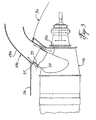
- the aircraft construction as shown in Figs. 1 and 2, has an aircraft engine 1 mounted within a nacelle 3.
- a cowl door 5 is provided in the wall 7 of the nacelle 3, the door 5 being hinged at the bottom by a hinge 9 to the wall 7.
- An exhaust duct 11 extends rearwardly, and toward the side, from the engine 1 through the cowl door 5 to direct exhaust from the engine 1 outside the nacelle 3.
- the exhaust duct 11, in accordance with the present invention, is made in two sections.
- the first duct section 15 of the duct 11 is fixed to the engine 1 and leads rearwardly therefrom and toward the side toward the cowl door 5.
- the second duct section 17 of the duct 11 is mounted in the cowl door 5 and leads outside.
- the outlet end 19 of the first duct section 15, and the inlet end 21 of the second duct section 17 have flanges 23, 25 respectively thereon.
- a ring seal 27 is provided on flange 23 to abut the other flange 25 when the cowl door 5 is closed to form a complete, closed, exhaust duct 11 for directing exhaust from the engine 1 out of the nacelle 3.
- the ring seal 27 could be provided on the other flange 25 if desired.
- the cowl door 5 When the engine is to be serviced, the cowl door 5 is opened and moved downwardly out of the way about hinge 9, taking the second duct section 17 of the exhaust duct 11 away with it. With a good portion of the exhaust duct 11 removed, servicing of the engine 1 is much easier. After servicing, the cowl door 5 is closed, and the inlet end 21 of the second duct section 17 abuts the seal 27 on the outlet end 19 of the first duct section 15 to form the complete, closed, exhaust duct 11.
- the exhaust duct 11 can be modified to incorporate an ejector slot 37 for ejecting heated air out of the nacelle 3 while also getting rid of the engine exhaust.
- the exhaust duct 11a is modified so the first duct section 15a has an outlet end portion 33 that is smaller than the inlet end portion 35 of the second duct section 17a.
- the outlet end portion 33 of the first duct section 15a fits concentrically within the inlet end portion 35 of the second duct section 17a and extends into the inlet end portion 35 for a short distance.
- the portion 33 may also be offset with respect to section 17a, rather than being purely concentric.
- An annular ejector slot 37 is formed at the junction of the two duct sections 15a, 17a.
- the exhaust duct 11b can include an adapter 41 as shown in Fig. 4.
- the adapter 41 has a flange 43 on its inlet end 45 which is sized to abut a flange 47 on the outlet end 49 of the first duct section 11b.
- Suitable fasteners 51 detachably connect the flanges 43, 47 together to join the adapter 41 to the first duct section 11b.
- the outlet end 53 of the adapter 41 is sized to fit concentrically within the inlet end 55 of the second duct section 17b, or offset with respect to section 17b, and to extend part way into it, to form an annular ejector slot 37b.
- the exhaust from the engine 1b is directed out through the first duct section lib, the adapter 41, and the second duct section 17b in series.
- the ejector slot 37b ejects hot air from within the nacelle 3b.
- opening the cowl door 5b moves the second duct section 17b out of the way to allow easier servicing of the engine 1b.
- the adapter 41 being detachable, can be easily changed to use one of a number of adapters, each having a different size of outlet end 53 so as to be able to change the size the ejector slot 37b. If an ejector slot 37b is not required, the adapter 41 could be modified to mate with the inlet end 55 of the second duct section 17b, carrying a seal (not shown) on its outlet end 53 against which the inlet end 55 of the second duct section 17b would abut when the cowl door 5b is closed.
Landscapes
- Engineering & Computer Science (AREA)
- Mechanical Engineering (AREA)
- General Engineering & Computer Science (AREA)
- Chemical & Material Sciences (AREA)
- Combustion & Propulsion (AREA)
- Aviation & Aerospace Engineering (AREA)
- Exhaust Silencers (AREA)
- Jet Pumps And Other Pumps (AREA)
Claims (9)
- Flugzeugkonstruktion mit einem Flugzeugtriebwerk (1; 1a; 1b), einer Triebwerkgondel (3,; 3a; 3b) mit einer Wand (7), welche das Triebwerk einschließt; einer Triebwerkverkleidungsklappe (5; 5a; 5b) in der Wand der Gondel, welche Zugang zu dem Triebwerk schafft, um dieses zu warten; einen Abgaskanal (11; 11a), welcher sich von dem Triebwerk durch die Triebwerkverkleidungsklappe erstreckt,
dadurch gekennzeichnet, dass der Abgaskanal einen ersten Kanalabschnitt (15; 15a; 11b) mit einem Auslassende (19; 49), welcher sich von dem Triebwerk in Richtung zur Triebwerkverkleidungsklappe erstreckt, wobei sein Auslassende der Triebwerkverkleidungsklappe benachbart ist, und einen zweiten separaten Kanalabschnitt (17; 17a; 17b) aufweist, der ein Einlassende (21; 45) aufweist, welcher in der Triebwerkverkleidungsklappe angebracht ist und mit der Triebwerkverkleidungsklappe beweglich ist, wobei das Einlassende des zweiten Kanalabschnitts dem Auslassende des ersten Kanalabschnitts benachbart ist, wenn die Triebwerkverkleidungsklappe geschlossen ist, so dass der erste und der zweite Kanalabschnitt zusammen Abgas von dem Triebwerk aus der Gondel lenken. - Flugzeugkonstruktion nach Anspruch 1, wobei die Triebwerkverkleidungsklappe (5; 5a; 5b) an ihrem unteren Rand an der Wand (7) drehbar angeschlossen ist, wobei die Triebwerkverkleidungsklappe den zweiten Kanalabschnitt (17; 17a; 17b) weg von dem Triebwerk (1; 1a; 1b) bringt, wenn die Triebwerkverkleidungsklappe geöffnet wird, um einen größeren Zugang zu dem Triebwerk zu schaffen, wenn das Triebwerk gewartet wird.
- Flugzeugkonstruktion nach Anspruch 1 oder 2, wobei das Auslassende (19; 49) und das Einlassende (21; 45) des ersten Kanalabschnitts (15; 15a; 11b) bzw. des zweiten Kanalabschnitts (17; 17a; 17b) mit einer Ringdichtung (27), die zwischen diesen positioniert ist, aneinander angrenzen, wobei die Ringdichtung an dem Einlasskanalende oder dem Auslasskanalende angebracht ist.
- Flugzeugkonstruktion nach Anspruch 1 oder 2, wobei der Bereich des ersten Kanalabschnitts (15; 15a; 11b) an seinem Auslassende (19; 49) etwas kleiner ist als der Bereich des zweiten Kanalabschnitts (17; 17a; 17b) an seinem Einlassende (21; 45), wobei das Auslassende des ersten Kanalabschnitts generell konzentrisch zu dem und etwas innerhalb des Einlassendes des zweiten Kanalabschnitts angebracht ist, um einen ringförmigen Ejektorschlitz (37; 37b) in dem Abgaskanal (11; 11a) zum Abgeben von Luft von innerhalb der Gondel (3; 3a; 3b) zusammen mit dem Abgas von der Maschine (1; 1a; 1b) zu bilden, wenn die Triebwerkverkleidungsklappe (5; 5a; 5b) geschlossen ist.
- Flugzeugkonstruktion nach einem der Ansprüche 1, 2 oder 4, wobei der Abgaskanal (11; 11a) einem an dem Auslassende (19; 49) des ersten Kanalabschnitts (15; 15a; 11b) angebrachten Adapter (41) aufweist, wobei der Adapter ein Auslassende (53) hat, welches kleiner ist als das Einlassende (21; 45) des zweiten Kanalabschnitts (17; 17a; 17b), wobei das Auslassende des Adapters generell konzentrisch zu dem und etwas innerhalb des Einlassendes des zweiten Kanalabschnitts passt, wenn die Triebwerkverkleidungsklappe (5; 5a; 5b) geschlossen ist, um einen ringförmigen Ejektorschlitz (37; 37b) in dem Abgaskanal zu bilden, zum Abgeben von Luft aus der Gondel (3; 3a; 3b).
- Flugzeugkonstruktion nach Anspruch 5, wobei der Adapter (41) lösbar an dem ersten Kanalabschnitt (15; 15a; 11b) angeschlossen ist, so dass die Größe des Ejektorschlitzes (37; 37b) durch Ändern des Adapters variiert werden kann.
- Flugzeugkonstruktion nach einem der vorangehenden Ansprüche, wobei die Flugzeugkonstruktion ein Hubschrauberrumpf ist.
- Flugzeugkonstruktion nach einem der vorangehenden Ansprüche, wobei die Flugzeugkonstruktion ein Tiltrotorrumpf ist.
- Flugzeugkonstruktion mit einem Abgasadapter (41), wobei das Flugzeug ein Flugzeugtriebwerk (1; 1a; 1b) hat, das in einer Triebwerkgondel (3; 3a; 3b) mit einer das Triebwerk einschließenden Wand (7) und einer Triebwerkverkleidungsklappe (5; 5a; 5b) in der Wand der Gondel, die Zugang zu dem Triebwerk schafft, um es zu warten, angebracht ist,
dadurch gekennzeichnet, dass das Triebwerk einen Abgaskanal (11; 11a) mit einer von einem Flansch (47) umgebenen Auslassöffnung (19; 49) aufweist, wobei die Triebwerkverkleidungsklappe eine mit dem Abgaskanalauslass zusammenfallenden Öffnung definiert, wobei der Abgasadapter von einem Kanal mit einem Flansch (43) gebildet ist, der daran angepasst ist, an den Flansch des Abgaskanals an dem Triebwerk angebracht zu werden und der Adapter eine kurze Strecke durch die Öffnung in der Triebwerkverkleidungsklappe ragt, wenn die Triebwerkverkleidungsklappe geschlossen ist.
Applications Claiming Priority (3)
| Application Number | Priority Date | Filing Date | Title |
|---|---|---|---|
| US63926 | 1998-04-22 | ||
| US09/063,926 US6109562A (en) | 1998-04-22 | 1998-04-22 | Aircraft construction |
| PCT/CA1999/000353 WO1999054204A1 (en) | 1998-04-22 | 1999-04-21 | Jet engine exhaust nozzle |
Publications (2)
| Publication Number | Publication Date |
|---|---|
| EP1071609A1 EP1071609A1 (de) | 2001-01-31 |
| EP1071609B1 true EP1071609B1 (de) | 2003-07-02 |
Family
ID=22052409
Family Applications (1)
| Application Number | Title | Priority Date | Filing Date |
|---|---|---|---|
| EP99915426A Expired - Lifetime EP1071609B1 (de) | 1998-04-22 | 1999-04-21 | Schubdüse einer gasturbine |
Country Status (6)
| Country | Link |
|---|---|
| US (1) | US6109562A (de) |
| EP (1) | EP1071609B1 (de) |
| JP (1) | JP2002512151A (de) |
| CA (1) | CA2329343C (de) |
| DE (1) | DE69909276T2 (de) |
| WO (1) | WO1999054204A1 (de) |
Families Citing this family (12)
| Publication number | Priority date | Publication date | Assignee | Title |
|---|---|---|---|---|
| KR20040105862A (ko) * | 2002-04-10 | 2004-12-16 | 피셔 앤 페이켈 어플라이언스 리미티드 | 세탁기 |
| FR2905984B1 (fr) * | 2006-09-20 | 2011-12-30 | Turbomeca | Moteur d'helicoptere a turbine a gaz a emission sonore reduite par traitement acoustique d'un ejecteur |
| CA2830938C (en) | 2011-04-28 | 2015-03-24 | Bell Helicopter Textron Inc. | Self-aligning inlet plenum system for rotorcraft |
| US20140060004A1 (en) * | 2011-09-20 | 2014-03-06 | Bell Helicopter Textron Inc. | Tiltrotor vectored exhaust system |
| US9969500B2 (en) * | 2014-02-06 | 2018-05-15 | Honeywell International Inc. | Bifurcated ducts including plenums for stabilizing flow therethrough and exhaust systems including the same |
| US10279924B2 (en) * | 2017-05-12 | 2019-05-07 | Bell Helicopter Textron Inc. | Engine exhaust duct mounting assembly |
| CN109606709A (zh) * | 2018-11-14 | 2019-04-12 | 中国直升机设计研究所 | 一种用于直升机的排气管安装结构 |
| CN114178790B (zh) * | 2021-12-08 | 2023-03-17 | 中国航发南方工业有限公司 | 发动机排气段制作工艺 |
| US11732633B2 (en) * | 2022-01-04 | 2023-08-22 | Caterpillar Inc. | Exhaust discharge system |
| FR3140117A1 (fr) | 2022-09-27 | 2024-03-29 | Airbus Helicopters | Aéronef muni d’un moteur et d’un conduit d’échappement drainé autour d’une tuyère d’éjection du moteur |
| FR3141681B1 (fr) * | 2022-11-09 | 2025-03-21 | Airbus Helicopters | Aéronef muni d’un conduit d’échappement couplé à un système de stabilisation |
| CN116280225B (zh) * | 2023-02-08 | 2026-04-14 | 中国航发湖南动力机械研究所 | 一种直升机侧向排气管及辅助装置 |
Family Cites Families (13)
| Publication number | Priority date | Publication date | Assignee | Title |
|---|---|---|---|---|
| US2231239A (en) * | 1939-05-16 | 1941-02-11 | Curtiss Wright Corp | Cowling exhaust outlet |
| US2650666A (en) * | 1946-07-25 | 1953-09-01 | Dorand Rene | Rotary-wing aircraft with jet-driven rotor |
| US2605851A (en) * | 1946-11-30 | 1952-08-05 | Chrysler Corp | Air intake for aircraft turbopropeller power plant |
| US2653585A (en) * | 1949-12-22 | 1953-09-29 | United Aircraft Corp | Engine cooling and exhaust arrangement |
| FR1512579A (fr) * | 1966-12-30 | 1968-02-09 | Sud Aviation | Dispositif sustentateur et propulseur pour appareil à réaction du type combiné hélicoptère-autogire |
| GB2044359B (en) * | 1979-03-16 | 1982-10-27 | Rolls Royce | Gas turbine engine air intakes |
| US4369937A (en) * | 1981-05-18 | 1983-01-25 | The United States Of America As Represented By The Secretary Of The Army | Hinging and latching apparatus |
| US4388804A (en) * | 1981-08-17 | 1983-06-21 | J. I. Case Company | Exhaust assembly for tractors |
| US4552309A (en) * | 1982-04-07 | 1985-11-12 | Rolls-Royce Inc. | Variable geometry nozzles for turbomachines |
| US4519543A (en) * | 1982-04-07 | 1985-05-28 | Rolls-Royce Inc. | Vectorable nozzles for turbomachines |
| GB2266080A (en) * | 1992-04-16 | 1993-10-20 | Rolls Royce Plc | Mounting arrangement for a gas turbine engine. |
| DE19524731A1 (de) * | 1995-07-07 | 1997-01-09 | Bmw Rolls Royce Gmbh | Turboprop-Triebwerk mit einem Luft-Ölkühler |
| CA2226441C (en) * | 1995-07-07 | 2007-01-23 | Kurt Steiner | Turboprop engine with an air-oil cooler |
-
1998
- 1998-04-22 US US09/063,926 patent/US6109562A/en not_active Expired - Lifetime
-
1999
- 1999-04-21 WO PCT/CA1999/000353 patent/WO1999054204A1/en not_active Ceased
- 1999-04-21 EP EP99915426A patent/EP1071609B1/de not_active Expired - Lifetime
- 1999-04-21 CA CA002329343A patent/CA2329343C/en not_active Expired - Lifetime
- 1999-04-21 JP JP2000544562A patent/JP2002512151A/ja active Pending
- 1999-04-21 DE DE69909276T patent/DE69909276T2/de not_active Expired - Fee Related
Also Published As
| Publication number | Publication date |
|---|---|
| DE69909276D1 (de) | 2003-08-07 |
| EP1071609A1 (de) | 2001-01-31 |
| CA2329343C (en) | 2007-05-15 |
| US6109562A (en) | 2000-08-29 |
| DE69909276T2 (de) | 2004-02-05 |
| CA2329343A1 (en) | 1999-10-28 |
| JP2002512151A (ja) | 2002-04-23 |
| WO1999054204A1 (en) | 1999-10-28 |
Similar Documents
| Publication | Publication Date | Title |
|---|---|---|
| EP1071609B1 (de) | Schubdüse einer gasturbine | |
| US4002024A (en) | Infrared suppression system for a gas turbine engine | |
| EP1257468B1 (de) | Lufteinlasswirbeldämpfer und eisschutzvorrichtung für hilfstriebwerke | |
| US3921906A (en) | Infrared suppression system for a gas turbine engine | |
| US8528857B2 (en) | Translatable jet engine thrust reverser configuration providing improved maintenance access | |
| US5655359A (en) | Passive cooling device and method for cooling an auxiliary power unit on an airplane | |
| EP1607611B1 (de) | System zum Antrieb eines Flugzeuges mit einer Vorrichtung zum Unterdrücken der Infrarotsignatur | |
| US11428190B2 (en) | Grid-type thrust reverser for turbojet engine | |
| CA2703115A1 (en) | Passive cooling system for auxiliary power unit installation | |
| CN101277871A (zh) | 包括发动机以及用于发动机的挂架的飞机发动机组件 | |
| GB2312251A (en) | Ducted fan gas turbine engine mounting | |
| US20130037122A1 (en) | Pressure influencing assembly for an aircraft auxiliary system | |
| US8371522B2 (en) | Device for cooling hot gas to be discharged from an aircraft | |
| RU2162536C2 (ru) | Двухконтурный турбореактивный двигатель, связанный с устройством реверсирования тяги с обтекателем, установленным в канале газового потока | |
| US9410485B2 (en) | Composite panel having a built-in duct | |
| US20110272533A1 (en) | Jet engine nacelle intended to equip an aircraft | |
| CN102209667A (zh) | 具有可移动上游罩的涡轮喷气发动机机舱 | |
| JP2005133713A (ja) | フレード式エンジンノズルのための方法及び装置 | |
| CN113811487A (zh) | 短舱进气道和包括这种进气道的短舱 | |
| US20170321634A1 (en) | Nacelle rear assembly for a turbojet engine comprising a suspension cradle | |
| US4662174A (en) | Plume diluter diverter assembly for a turbine engine of a heavier than air machine | |
| EP3604140B1 (de) | Lufteinlasssystem für hilfsaggregate | |
| EP4257481A1 (de) | Gondeleinlassstrukturanpassung mit positionsklammer und hebeklammer | |
| GB2235728A (en) | Jet engine exhaust nozzle hinge | |
| US10239628B2 (en) | Set of latches with identical components for nacelle doors |
Legal Events
| Date | Code | Title | Description |
|---|---|---|---|
| PUAI | Public reference made under article 153(3) epc to a published international application that has entered the european phase |
Free format text: ORIGINAL CODE: 0009012 |
|
| 17P | Request for examination filed |
Effective date: 20001019 |
|
| AK | Designated contracting states |
Kind code of ref document: A1 Designated state(s): DE FR GB IT SE |
|
| 17Q | First examination report despatched |
Effective date: 20020219 |
|
| GRAH | Despatch of communication of intention to grant a patent |
Free format text: ORIGINAL CODE: EPIDOS IGRA |
|
| RAP1 | Party data changed (applicant data changed or rights of an application transferred) |
Owner name: PRATT & WHITNEY CANADA CORP. |
|
| GRAH | Despatch of communication of intention to grant a patent |
Free format text: ORIGINAL CODE: EPIDOS IGRA |
|
| GRAA | (expected) grant |
Free format text: ORIGINAL CODE: 0009210 |
|
| AK | Designated contracting states |
Designated state(s): DE FR GB IT SE |
|
| PG25 | Lapsed in a contracting state [announced via postgrant information from national office to epo] |
Ref country code: IT Free format text: LAPSE BECAUSE OF FAILURE TO SUBMIT A TRANSLATION OF THE DESCRIPTION OR TO PAY THE FEE WITHIN THE PRESCRIBED TIME-LIMIT;WARNING: LAPSES OF ITALIAN PATENTS WITH EFFECTIVE DATE BEFORE 2007 MAY HAVE OCCURRED AT ANY TIME BEFORE 2007. THE CORRECT EFFECTIVE DATE MAY BE DIFFERENT FROM THE ONE RECORDED. Effective date: 20030702 |
|
| REG | Reference to a national code |
Ref country code: GB Ref legal event code: FG4D |
|
| REF | Corresponds to: |
Ref document number: 69909276 Country of ref document: DE Date of ref document: 20030807 Kind code of ref document: P |
|
| PG25 | Lapsed in a contracting state [announced via postgrant information from national office to epo] |
Ref country code: SE Free format text: LAPSE BECAUSE OF FAILURE TO SUBMIT A TRANSLATION OF THE DESCRIPTION OR TO PAY THE FEE WITHIN THE PRESCRIBED TIME-LIMIT Effective date: 20031002 |
|
| ET | Fr: translation filed | ||
| PLBE | No opposition filed within time limit |
Free format text: ORIGINAL CODE: 0009261 |
|
| STAA | Information on the status of an ep patent application or granted ep patent |
Free format text: STATUS: NO OPPOSITION FILED WITHIN TIME LIMIT |
|
| 26N | No opposition filed |
Effective date: 20040405 |
|
| PGFP | Annual fee paid to national office [announced via postgrant information from national office to epo] |
Ref country code: DE Payment date: 20080430 Year of fee payment: 10 |
|
| PG25 | Lapsed in a contracting state [announced via postgrant information from national office to epo] |
Ref country code: DE Free format text: LAPSE BECAUSE OF NON-PAYMENT OF DUE FEES Effective date: 20091103 |
|
| REG | Reference to a national code |
Ref country code: FR Ref legal event code: PLFP Year of fee payment: 18 |
|
| REG | Reference to a national code |
Ref country code: FR Ref legal event code: PLFP Year of fee payment: 19 |
|
| REG | Reference to a national code |
Ref country code: FR Ref legal event code: PLFP Year of fee payment: 20 |
|
| PGFP | Annual fee paid to national office [announced via postgrant information from national office to epo] |
Ref country code: GB Payment date: 20180321 Year of fee payment: 20 |
|
| PGFP | Annual fee paid to national office [announced via postgrant information from national office to epo] |
Ref country code: FR Payment date: 20180322 Year of fee payment: 20 |
|
| REG | Reference to a national code |
Ref country code: GB Ref legal event code: PE20 Expiry date: 20190420 |
|
| PG25 | Lapsed in a contracting state [announced via postgrant information from national office to epo] |
Ref country code: GB Free format text: LAPSE BECAUSE OF EXPIRATION OF PROTECTION Effective date: 20190420 |