EP1071162A1 - Junction connector for wire harness - Google Patents
Junction connector for wire harness Download PDFInfo
- Publication number
- EP1071162A1 EP1071162A1 EP00402047A EP00402047A EP1071162A1 EP 1071162 A1 EP1071162 A1 EP 1071162A1 EP 00402047 A EP00402047 A EP 00402047A EP 00402047 A EP00402047 A EP 00402047A EP 1071162 A1 EP1071162 A1 EP 1071162A1
- Authority
- EP
- European Patent Office
- Prior art keywords
- bus bar
- bus bars
- connector
- bus
- bar layer
- Prior art date
- Legal status (The legal status is an assumption and is not a legal conclusion. Google has not performed a legal analysis and makes no representation as to the accuracy of the status listed.)
- Granted
Links
Images


Classifications
-
- H—ELECTRICITY
- H05—ELECTRIC TECHNIQUES NOT OTHERWISE PROVIDED FOR
- H05K—PRINTED CIRCUITS; CASINGS OR CONSTRUCTIONAL DETAILS OF ELECTRIC APPARATUS; MANUFACTURE OF ASSEMBLAGES OF ELECTRICAL COMPONENTS
- H05K3/00—Apparatus or processes for manufacturing printed circuits
- H05K3/40—Forming printed elements for providing electric connections to or between printed circuits
- H05K3/4038—Through-connections; Vertical interconnect access [VIA] connections
- H05K3/4084—Through-connections; Vertical interconnect access [VIA] connections by deforming at least one of the conductive layers
-
- H—ELECTRICITY
- H01—ELECTRIC ELEMENTS
- H01R—ELECTRICALLY-CONDUCTIVE CONNECTIONS; STRUCTURAL ASSOCIATIONS OF A PLURALITY OF MUTUALLY-INSULATED ELECTRICAL CONNECTING ELEMENTS; COUPLING DEVICES; CURRENT COLLECTORS
- H01R9/00—Structural associations of a plurality of mutually-insulated electrical connecting elements, e.g. terminal strips or terminal blocks; Terminals or binding posts mounted upon a base or in a case; Bases therefor
- H01R9/22—Bases, e.g. strip, block, panel
- H01R9/226—Bases, e.g. strip, block, panel comprising a plurality of conductive flat strips providing connection between wires or components
-
- H—ELECTRICITY
- H01—ELECTRIC ELEMENTS
- H01R—ELECTRICALLY-CONDUCTIVE CONNECTIONS; STRUCTURAL ASSOCIATIONS OF A PLURALITY OF MUTUALLY-INSULATED ELECTRICAL CONNECTING ELEMENTS; COUPLING DEVICES; CURRENT COLLECTORS
- H01R9/00—Structural associations of a plurality of mutually-insulated electrical connecting elements, e.g. terminal strips or terminal blocks; Terminals or binding posts mounted upon a base or in a case; Bases therefor
- H01R9/22—Bases, e.g. strip, block, panel
- H01R9/24—Terminal blocks
-
- H—ELECTRICITY
- H05—ELECTRIC TECHNIQUES NOT OTHERWISE PROVIDED FOR
- H05K—PRINTED CIRCUITS; CASINGS OR CONSTRUCTIONAL DETAILS OF ELECTRIC APPARATUS; MANUFACTURE OF ASSEMBLAGES OF ELECTRICAL COMPONENTS
- H05K1/00—Printed circuits
- H05K1/02—Details
- H05K1/0286—Programmable, customizable or modifiable circuits
- H05K1/0287—Programmable, customizable or modifiable circuits having an universal lay-out, e.g. pad or land grid patterns or mesh patterns
- H05K1/0289—Programmable, customizable or modifiable circuits having an universal lay-out, e.g. pad or land grid patterns or mesh patterns having a matrix lay-out, i.e. having selectively interconnectable sets of X-conductors and Y-conductors in different planes
-
- H—ELECTRICITY
- H05—ELECTRIC TECHNIQUES NOT OTHERWISE PROVIDED FOR
- H05K—PRINTED CIRCUITS; CASINGS OR CONSTRUCTIONAL DETAILS OF ELECTRIC APPARATUS; MANUFACTURE OF ASSEMBLAGES OF ELECTRICAL COMPONENTS
- H05K2201/00—Indexing scheme relating to printed circuits covered by H05K1/00
- H05K2201/10—Details of components or other objects attached to or integrated in a printed circuit board
- H05K2201/10227—Other objects, e.g. metallic pieces
- H05K2201/10272—Busbars, i.e. thick metal bars mounted on the PCB as high-current conductors
-
- H—ELECTRICITY
- H05—ELECTRIC TECHNIQUES NOT OTHERWISE PROVIDED FOR
- H05K—PRINTED CIRCUITS; CASINGS OR CONSTRUCTIONAL DETAILS OF ELECTRIC APPARATUS; MANUFACTURE OF ASSEMBLAGES OF ELECTRICAL COMPONENTS
- H05K2203/00—Indexing scheme relating to apparatus or processes for manufacturing printed circuits covered by H05K3/00
- H05K2203/06—Lamination
- H05K2203/063—Lamination of preperforated insulating layer
-
- Y—GENERAL TAGGING OF NEW TECHNOLOGICAL DEVELOPMENTS; GENERAL TAGGING OF CROSS-SECTIONAL TECHNOLOGIES SPANNING OVER SEVERAL SECTIONS OF THE IPC; TECHNICAL SUBJECTS COVERED BY FORMER USPC CROSS-REFERENCE ART COLLECTIONS [XRACs] AND DIGESTS
- Y10—TECHNICAL SUBJECTS COVERED BY FORMER USPC
- Y10S—TECHNICAL SUBJECTS COVERED BY FORMER USPC CROSS-REFERENCE ART COLLECTIONS [XRACs] AND DIGESTS
- Y10S439/00—Electrical connectors
- Y10S439/949—Junction box with busbar for plug-socket type interconnection with receptacle
Landscapes
- Engineering & Computer Science (AREA)
- Microelectronics & Electronic Packaging (AREA)
- Manufacturing & Machinery (AREA)
- Connection Or Junction Boxes (AREA)
- Multi-Conductor Connections (AREA)
- Connections Effected By Soldering, Adhesion, Or Permanent Deformation (AREA)
Abstract
Description
- The present invention relates to a junction connector incorporated into wire harnesses used in automobiles. More particularly, the invention concerns a junction connector, in which electrical cables can be connected from different directions.
- The wiring of harnesses in an automobile also involves the installation of electrical connector housings, such as junction boxes, comprising internal circuits. When a splicing operation cannot be carried out in the internal circuits, the junction connector is connected to electrical cables, prior to the splicing operation. In such a case, junction connectors having a structure shown in Fig. 1 are commonly used.
- The
above junction connector 1 includes acase 2 with a fitting recess la. The fitting recess contains a plurality ofjunction bus bars 3 provided withrespective tabs 3a. Electrical cables w are branched out from a wire harness W/H. The edges of such electrical cables w are provided with terminals. These terminals are inserted into aconnector 4 and locked therein. Theconnector 4 is then engaged with thefitting recess 1a in thejunction connector 1 and locked, whereby the electrical cables w are joined. Theconnector 4 and thejunction connector 1 are bound to the wire harness W/H by taping. - In the
above junction connector 1, thetabs 3a of thejunction bus bars 3 are oriented in the same direction. Moreover, thejunction connector 1 has only onefitting recess 1a through which thecounterpart connector 4 is fitted. Because of this single orientation of thefitting recess 1a, thejunction connector 1 can receive thecounterpart connector 4 only from one direction. - As shown in Fig.2, the wire harnesses W/H, e.g. W/H-1, -2, -3 and -4 may be wired in a T or cross configuration. However, the
junction connector 1 can receive only onecounterpart connector 4 from one direction. Therefore, when some electrical cables of these wire harnesses W/H need to be spliced, the electrical cables to be spliced are forcibly inserted into a wire harness W/H, as shown in Fig. 1, so that the wire harnesses W/H are connected to thejunction connector 1. - In the above structure, the wire harnesses W/H, and the constituent electrical cables w connecting to the
junction connector 1, are not configured in the most suitable way. Furthermore, setting-up positions of the junction connector get restricted, so that the junction connector cannot always be placed appropriately in the limited space of an automobile. - In view of the above, an object of the present invention is to provide a junction connector which can be connected from a plurality of directions, enables optimum arrangements, distributions or divisions of wire harnesses, and which can be arranged in an appropriate position inside the effective space of an automobile.
- To this end, there is provided a junction connector comprising a shell which contains junction circuits and at least two connector-fitting portions oriented in different directions. The junction circuits comprise at least a first bus bar layer and a second bus bar layer, which include first and second bus bars, respectively. Further, the first and second bus bars have two respective end tabs and are aligned at a given interval from each other in the same direction, respectively. The second bus bar layer is then superposed on the first bus bar layer such that the direction of the second bus bars are skewed relative to that of the first bus bars, thereby forming cross points between the first bus bars and the second bus bars. The first and second bus bars are then bonded through the cross points, thereby forming junction circuits.
- In this junction connector structure, the orientation of connector-fitting portions can be very easily arranged in different directions. Accordingly, when electrical cables are splice-connected through the junction connector, there is no need to group them in one wire harness. There is no need either to group several wire harnesses into one direction by force. Instead, they can be brought into the junction connector from a plurality of directions. The circuits can thus be designed as a function of the wired state of wire harnesses and/or the set-up space for the junction connector. As a result, wire harnesses can be arranged, divided or distributed in an optimum way.
- In the above junction connector, the shell defines peripheral rims. The second bus bar layer may then be superposed on the first bus bar layer such that the second bus bars are arranged perpendicular to the first bus bars. Further, the shell may include at least three connector-fitting portions which are provided on the peripheral rims and separated at an angle of 90 degrees from each other around the center axis of the shell. The connector-fitting portions may then contain the end tabs of the first and second bus bars.
- As a variant, at least one of the at least first and second bus bar layers may include at least one bus bar comprising upwardly- and/or downwardly-bent end tabs, and the shell may comprise corresponding upward- and/or downward connector-fitting portions.
- The connector-fitting portions may be arranged at an angle of 90 degrees from each other in the horizontal direction, measured around the center axis of the shell. Further, an upward and a downward connector-fitting portion may be added, bringing the total number of connector-fitting portions to six.
- Where necessary, the number of bus bar layers may be more than two. A bus bar layer may be added in a crossed direction over the adjacent bus bar layer, but it can also be laid out at a desired skewed angle, e.g. at 45 degrees. In this manner, multi-directional connector-fitting portions may be produced.
- Preferably, an insulating sheet is interposed between the at least a first bus bar layer and the second bus bar layer. The insulating sheet is provided with openings at the positions corresponding to the cross points. The first bus bars included in the first bus bar layer are then bent into the openings, so that they are brought into contact with the second bus bars included in the second bus bar layer, and joined therewith.
- As another variant, the junction connector further comprises a third bus bar layer with corresponding third bus bars and end tabs likewise arranged. The third bus bar layer is then superposed on the second bus bar layer such that the direction of the third bus bars is skewed relative to that of the second bus bars, thereby forming cross points between the second bus bars and the third bus bars. The second and third bus bars are then bonded through the cross points, thereby forming junction circuits.
- Preferably, a second insulating sheet is interposed between the second bus bar layer and the third bus bar layer. The second insulating sheets is then provided with openings at positions corresponding to the cross points. The second bus bars and the third bus bars are bent into the openings, so that the second bus bars are brought into contact with the third bus bars through the openings, and bonded therewith.
- The above and the other objects, features and advantages of the present invention will be made apparent from the following description of the preferred embodiments, given as non-limiting examples, with reference to the accompanying drawings, in which:
- Fig. 1 is a perspective view of a wire harness, a connector and a junction connector known in the prior art;
- Fig.2 is a view schematically showing how wire harnesses are joined to a connector according to the prior art;
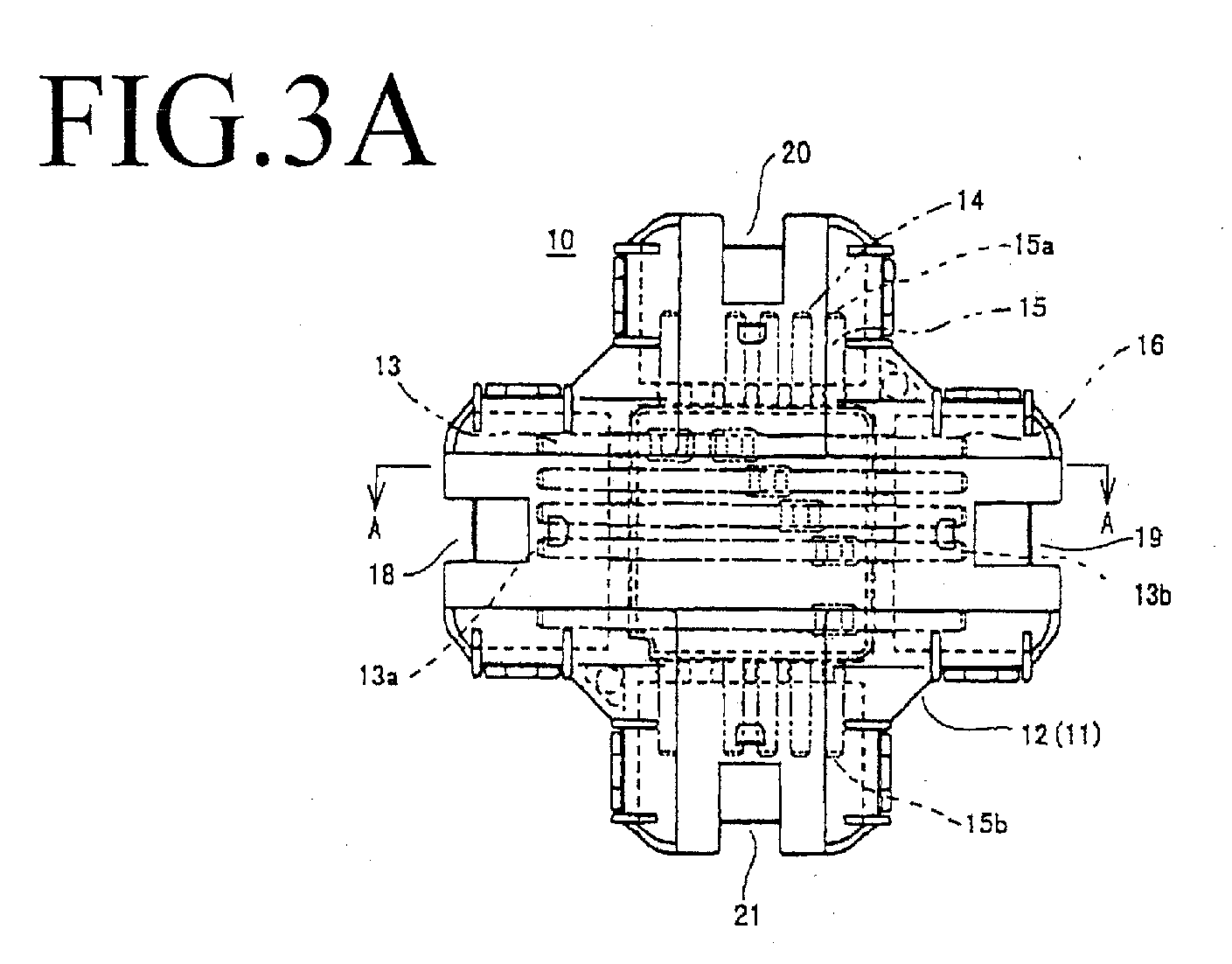
- Fig.3A is a top plan view of the junction connector according to a first embodiment of the invention;
- Fig.3B is a schematic view showing the fitting directions between wire harness ends and the junction connector of Fig.3A;
- Fig.4A is a side view of the junction connector of Fig.3A;
- Fig.4B is a cross-sectional view along line A-A of the junction connector of Fig.3A;
- Fig.5A is a top plan view showing the arrangement between an X-directional bus bar layer and a Y-directional bus bar layer;
- Fig.5B is a top plan view when an insulating sheet is interposed between the X-directional bus bar layer and the Y-directional bus bar layer of Fig.5A;
- Fig.6A is a top plan view of an insulating sheet;
- Fig.6B is a cross-sectional view along line B-B of the insulating sheet of Fig.6A;
- Fig.6C is a cross-sectional view along line C-C of the insulating sheet of Fig.6A;
- Fig.7 is a cross-sectional view showing how two bus bar layers are connected through the insulating sheet;
- Fig.8 is a top plan view showing how bus bar layers are superposed according to a variant of the first embodiment of the invention;
- Fig.9 is a schematic view showing a location where the junction connector of Fig.8 is applied;
- Fig.10A is a cross-sectional view of the junction connector according to a second embodiment of the invention;
- Fig.10B is a cross-sectional view of a resistance-welded portion between the first and second bus bars of the junction connector of Fig.10A;
- Fig.11A is a top plan view of the junction connector according to a third embodiment of the invention;
- Fig.11B is a cross-section of the elevational side view of the junction connector of Fig.11A;
- Fig.12 is a top plan view of a variant according to the third embodiment of the invention; and
- Fig.13 is a cross-sectional view of a rivetted portion between the first and second bus bars of the junction connector according to a fourth embodiment of the invention.
-
- Figs.3 to 7 show a
junction connector 10 according to a first embodiment of the invention. Thejunction connector 10 comprises abottom shell 11 and atop shell 12, and the whole structure has a substantially thin square shape. Inside thejunction connector 10, first bus bars 13 in the form of a strip are arranged in parallel along the same direction (for example, the X direction), at a given spacing from each other, thereby forming a firstbus bar layer 14. Second bus bars 15 having the same shape are likewise arranged, but in a direction (Y direction) perpendicular to the X direction, so as to form a secondbus bar layer 16. These twolayers sheet 17 interposed therebetween. - The two faces of the insulating
sheet 17 are provided with a set ofgrooves 17a respectively in a cross arrangement. The first bus bars 13 in the firstbus bar layer 14 and the second bus bars 15 in the secondbus bar layer 16 are then fitted into thecrossing grooves 17a on the both sides of the insulatingsheet 17. When selected first bus bars 13 and second bus bars 15 are to be connected together, the connections are made through cross positions P1 to P6. To this end, the interposing insulatingsheet 17 comprisesopenings 17b. The bus bars 13 are then bent in a U shape, so as to be brought into contact with the bus bars 15. Both bus bars 13 and 15 are bonded in this state by resistance welding. When there is an unused portion in the circuitry, for example portion C in Fig.5A, the corresponding bus bar is removed from that portion. - The both ends of the bus bars 13 and 15 are provided with a
respective end tab bottom shell 11 and thetop shell 12 are joined, they define four sides. There are then provided connector-fittingportions end tabs portions junction connector 10 to be connected with counter-part connectors from different directions. - In this configuration, the
junction connector 10 is connected withconnectors 24 to 27 at 90° to each other, measured around the center axis of the shell. The splice circuits can thus be prepared as desired. Accordingly, to form splice circuits, it is no longer necessary to incorporate electrical cables into one wire harness. Instead, the electrical cables to be spliced can be divided into wire harnesses W/H-1, -2, -3 and -4 in a suitable way. - Fig.8 shows a variant of the first embodiment. The first
bus bar layer 14 and the secondbus bar layer 16 are formed in a junction circuit, as in the first embodiment. However, only one end of the second bus bars 15, which form the secondbus bar layer 16, includes anend tab 15a connecting to a counterpart connector, and the other end is left open. By contrast, the first bus bars 13, which form the firstbus bar layer 14, comprise the two ends respectively provided with anend tab junction connector 10 have three directions, and are disposed at a 90° angle to neighboring connector, around the center axis of the shell. - The
junction connector 10 including three connector-fitting portions may be installed in a rear lamp circuit as shown in Fig.9. Thejunction connector 10 can thus be mounted between floor harnesses W/H -1, -2 and -3, which extend in three directions. Desired splice circuits may thus be formed in an appropriate way. - Figs.10A and 10B show a second embodiment in which a third
bus bar layer 30 is aligned in the X direction and added to the first and second bus bar layers 14 and 16. The bus bar layers 14 and 30 arranged in the X direction thus flank thebus bar layer 16 arranged in the Y direction. Insulatingsheets - In order to connect the three bus bar layers 14, 16 and 30, the insulating sheet interposed between the two adjacent bus bar layers is provided with openings, as in the first embodiment. One of the bus bar layers is bent into a U shape, and thus brought into contact with the other bus bar layer. Both layers are then bonded by resistance welding.
- When splice-connecting many circuits, it suffices to increase the number of bus bar layers arranged either in the X or Y direction. Further, when an added bus bar layer is skewed by 45 degrees, instead of 90 degrees, relative to an adjacent layer along a bus bar direction, more than four connector-fitting portions can be formed in the horizontal direction.
- Fig.11 shows a third embodiment of the present invention, in which one end of the first bus bars 13, which constitute the X-directional first
bus bar layer 14, is bent upwards (in the top plan view of Fig.11), to formupward end tabs 13a'. The other end of the first bus bars 13 extends horizontally, so as to formhorizontal end tabs 13b. Furthermore, one end of the second bus bars 15, which constitute the Y-directional secondbus bar layer 16, is bent downwards to formdownward end tabs 15b'. The other end of the bus bars 15 extends horizontally, so as to formhorizontal end tabs 15a. - The bottom shell and the top shell include connector-fitting portions which are oriented along the directions of end tabs. For example, the bottom shell may comprise a downward connector-fitting portion from which the
end tabs 15b project, whilst the top shell may comprise an upward connector-fitting portion corresponding to theend tabs 13a. Further, the other connector-fitting portions may be provided on the outer rims of the bottom and top shells at an angle of 90 degrees around the center axis of the shell, from which theend tabs - In this manner, there are provided two horizontally-directed connector-fitting portions, and two connector-fitting portions directed upwards and downwards, respectively separated at an angle of 90 degrees around the center axis of the shell. Counterpart connectors can thus be connected from four different directions. Accordingly, the wire harnesses can be divided in the functionally most suitable way.
- Fig.12 shows a variant of the third embodiment of the invention, in which one end of some of the first bus bars 13, which constitute the X-directional first
bus bar layer 14, is bent upwards, so as to formupward end tabs 13a', whilst one end of the other first bus bars 13 formshorizontal end tabs 13a. Likewise, some of the second bus bars 15, which constitute the Y-directional secondbus bar layer 16, may have one end provided withdownward end tabs 15b', whilst one end of the other second bus bars 15 may be provided withhorizontal end tabs 15b. - Together with four horizontal connector-fitting portions formed at an interval of 90 degrees, there is further provided an upward and a downward connector-fitting portion, amounting to six connector-fitting portions with different directions.
- Fig.13 shows a fourth embodiment of the present invention, in which the X-directional first bus bars 13 and the Y-directional second bus bars 15 are joined by
rivets 40, instead of resistance welding. - In the junction connector according to the invention, connector-fitting portions, through which are fitted the counterpart connectors bound to wire harnesses, can be designed to be oriented in different directions as desired. The wire harnesses can thus be divided suitably, as a function of the wiring conditions, and their branching positions can be chosen depending on the effective space in an automobile.
- Furthermore, the internal circuits of the junction connector are made by combining bus bar strips. These bus bar strips can be produced very easily at a low cost.
Claims (6)
- A junction connector (10) comprising a shell containing junction circuits, characterised in thatsaid shell further contains at least two connector-fitting portions (18, 19, 20, 21) oriented along different directions,said junction circuits comprise at least a first bus bar layer (14) and a second bus bar layer (16), said first and second bus bar layers (14, 16) include first and second bus bars (13, 15), respectively, said first and second bus bars (13, 15) have two respective end tabs (13a, 13b, 15a, 15b) and are aligned at a given interval from each other in the same direction, respectively, said second bus bar layer (16) is superposed on said first bus bar layer (14) such that the direction of said second bus bars (15) is skewed relative to that of said first bus bars (13), thereby forming cross points (P1 to P6) between said first bus bars (13) and said second bus bars (15), and said first and second bus bars (13, 15) are bonded through said cross points (P1 to P6), thereby forming junction circuits.
- The junction connector according to claim 1, wherein said shell defines peripheral rims, said second bus bar layer (16) is superposed on said first bus bar layer (14) such that said second bus bars (15) are arranged perpendicular to said first bus bars (13), said shell includes at least three connector-fitting portions (18, 19, 20, 21) which are provided on said peripheral rims and separated at an angle of 90 degrees from each other around the center axis of said shell, and said connector-fitting portions (18, 19, 20, 21) contain said end tabs (13a, 13b, 15a, 15b) of said first and second bus bars (13, 15).
- The junction connector (10) according to claim 1 or 2, wherein at least one of said at least first and second bus bar layers (14, 16) includes at least one bus bar comprising upwardly- and/or downwardly-bent end tabs (13a', 15b'), and said shell comprises corresponding upward- and/or downward connector-fitting portions.
- The junction connector (10) according to any one of claims 1 to 3, wherein an insulating sheet ((17) is interposed between said at least a first bus bar layer (14) and a second bus bar layer (16), said insulating sheet (17) being provided with openings (17b) at positions corresponding to said cross points (P1 to P6), said first bus bars (13) included in said first bus bar layer (14) are bent into said openings (17b), so that they are brought into contact with said second bus bars (15) included in said second bus bar layer (16), and joined therewith.
- The junction connector (10) according to any one of claims 1 to 4, further comprising, in addition to said at least first and second bus bar layers, a third bus bar layer (30) with corresponding third bus bars and end tabs likewise arranged, wherein said third bus bar layer (30) is superposed on said second bus bar layer (16) such that the direction of said third bus bars is skewed relative to that of said second bus bars (15), thereby forming cross points between said second bus bars (15) and said third bus bars, said second and third bus bars being bonded through said cross points, thereby forming junction circuits.
- The junction connector (10) according to claim 5, wherein a second insulating sheet (31) is interposed between said second bus bar layer (16) and said third bus bar layer (30), said second insulating sheet (31) being provided with openings at positions corresponding to said cross points, and said second bus bars (15) and said third bus bars are bent into said openings, so that said second bus bars (15) are brought into contact with said third bus bars through said openings, and bonded therewith.
Applications Claiming Priority (2)
| Application Number | Priority Date | Filing Date | Title |
|---|---|---|---|
| JP11206402A JP2001035616A (en) | 1999-07-21 | 1999-07-21 | Joint connector for wire harness |
| JP20640299 | 1999-07-21 |
Publications (2)
| Publication Number | Publication Date |
|---|---|
| EP1071162A1 true EP1071162A1 (en) | 2001-01-24 |
| EP1071162B1 EP1071162B1 (en) | 2004-05-26 |
Family
ID=16522774
Family Applications (1)
| Application Number | Title | Priority Date | Filing Date |
|---|---|---|---|
| EP00402047A Expired - Lifetime EP1071162B1 (en) | 1999-07-21 | 2000-07-19 | Junction connector for wire harness |
Country Status (4)
| Country | Link |
|---|---|
| US (1) | US6635824B1 (en) |
| EP (1) | EP1071162B1 (en) |
| JP (1) | JP2001035616A (en) |
| DE (1) | DE60010985T2 (en) |
Cited By (3)
| Publication number | Priority date | Publication date | Assignee | Title |
|---|---|---|---|---|
| EP1124287A1 (en) * | 2000-02-01 | 2001-08-16 | Sumitomo Wiring Systems, Ltd. | Electrical joint connector |
| EP1391964A1 (en) * | 2002-08-22 | 2004-02-25 | WIELAND ELECTRIC GmbH | Electrical distributor |
| DE102004061527B4 (en) | 2003-12-22 | 2018-08-16 | Kabushiki Kaisha T An T | Busbar support for an interior light of a vehicle |
Families Citing this family (14)
| Publication number | Priority date | Publication date | Assignee | Title |
|---|---|---|---|---|
| JP2002186140A (en) * | 2000-12-15 | 2002-06-28 | Yazaki Corp | Circuit structure of electrical junction box, and method of forming the circuit |
| DE10117798A1 (en) * | 2001-04-10 | 2002-12-05 | Bosch Gmbh Robert | plug |
| US7322857B2 (en) * | 2006-04-03 | 2008-01-29 | Topower Computer Industrial Co., Ltd. | Electric power connector adapting structure |
| KR100659289B1 (en) | 2006-09-28 | 2006-12-20 | 주식회사 아람엔지니어링 | Bus duct for branching of electrical wiring |
| EP2074679A2 (en) * | 2006-10-13 | 2009-07-01 | Federal-Mogul Corporation | Wiring system |
| US8003888B2 (en) * | 2007-10-18 | 2011-08-23 | Federal-Mogul Ignition Company | Electrical junction assembly for wiring harness |
| JP5382525B2 (en) * | 2009-11-05 | 2014-01-08 | 住友電装株式会社 | Electrical junction box |
| US20150007487A1 (en) * | 2013-07-03 | 2015-01-08 | Rockwell Automation Technologies, Inc. | System and method for incorporation of pest repellent with bus bar cover components |
| DE102014116459A1 (en) * | 2013-11-11 | 2015-05-13 | Aees, Inc. | CABLE ASSEMBLY FOR VEHICLE WITH SOURCE SPLEISS OVERLAY |
| WO2016191662A1 (en) | 2015-05-27 | 2016-12-01 | Intelligent Technologies International, Inc. | Vehicle wire harness |
| JP6374894B2 (en) * | 2016-02-02 | 2018-08-15 | 矢崎総業株式会社 | Circuit body for vehicle |
| JP6353858B2 (en) * | 2016-02-22 | 2018-07-04 | 矢崎総業株式会社 | Wire harness structure |
| JP6562886B2 (en) | 2016-10-27 | 2019-08-21 | 矢崎総業株式会社 | Branch structure and wire harness |
| DE102018219466A1 (en) * | 2018-11-14 | 2020-05-14 | Audi Ag | Method for producing a current guiding device, junction box for a vehicle battery and motor vehicle |
Citations (4)
| Publication number | Priority date | Publication date | Assignee | Title |
|---|---|---|---|---|
| US2977672A (en) * | 1958-12-12 | 1961-04-04 | Gen Electric | Method of making bonded wire circuit |
| US5057026A (en) * | 1989-02-16 | 1991-10-15 | Yazaki Corporation | Electric junction box |
| JPH05326088A (en) * | 1992-05-14 | 1993-12-10 | Yazaki Corp | Joint connector |
| US5507668A (en) * | 1993-05-05 | 1996-04-16 | International Business Machines Corporation | Cable assembly for multiple electronic components |
Family Cites Families (14)
| Publication number | Priority date | Publication date | Assignee | Title |
|---|---|---|---|---|
| US2019625A (en) * | 1934-03-30 | 1935-11-05 | Rca Corp | Electrical apparatus |
| FR2666933B1 (en) * | 1990-09-19 | 1994-07-22 | Labinal | ELECTRICAL CONNECTION ELEMENT OF TWO ELECTRICAL CONDUCTORS AND BYPASS CONNECTOR USING SUCH AN ELEMENT. |
| US6140980A (en) * | 1992-03-13 | 2000-10-31 | Kopin Corporation | Head-mounted display system |
| US5501605A (en) * | 1993-06-07 | 1996-03-26 | Yazaki Corporation | Wiring harness assembly for vehicles |
| JP2833448B2 (en) * | 1993-11-08 | 1998-12-09 | 住友電装株式会社 | Branch junction box containing busbar and busbar forming material |
| JP2885029B2 (en) * | 1993-11-22 | 1999-04-19 | 住友電装株式会社 | Method of manufacturing electric junction box containing bus bar and electric junction box manufactured by the method |
| JP2929414B2 (en) * | 1994-07-05 | 1999-08-03 | 矢崎総業株式会社 | Electrical junction box |
| JP2924681B2 (en) * | 1994-12-28 | 1999-07-26 | 住友電装株式会社 | Electrical junction box |
| US5820404A (en) * | 1995-07-10 | 1998-10-13 | Sumitomo Wiring Systems, Ltd. | Terminal and cramping connector |
| US6264510B1 (en) * | 1997-05-28 | 2001-07-24 | Harness System Technologies Research Ltd. | Laser-welded bus bar structure |
| US6353190B1 (en) | 1998-10-09 | 2002-03-05 | Sumitomo Wiring Systems, Ltd. | Lattice-shaped circuit board |
| JP2000182682A (en) * | 1998-12-18 | 2000-06-30 | Sumitomo Wiring Syst Ltd | Electric junction box |
| JP3338004B2 (en) * | 1999-06-25 | 2002-10-28 | 株式会社オートネットワーク技術研究所 | Busbar connection structure |
| JP2001015951A (en) * | 1999-07-01 | 2001-01-19 | Sumitomo Wiring Syst Ltd | Electrical connection box |
-
1999
- 1999-07-21 JP JP11206402A patent/JP2001035616A/en active Pending
-
2000
- 2000-07-19 EP EP00402047A patent/EP1071162B1/en not_active Expired - Lifetime
- 2000-07-19 DE DE60010985T patent/DE60010985T2/en not_active Expired - Lifetime
- 2000-07-20 US US09/620,598 patent/US6635824B1/en not_active Expired - Fee Related
Patent Citations (4)
| Publication number | Priority date | Publication date | Assignee | Title |
|---|---|---|---|---|
| US2977672A (en) * | 1958-12-12 | 1961-04-04 | Gen Electric | Method of making bonded wire circuit |
| US5057026A (en) * | 1989-02-16 | 1991-10-15 | Yazaki Corporation | Electric junction box |
| JPH05326088A (en) * | 1992-05-14 | 1993-12-10 | Yazaki Corp | Joint connector |
| US5507668A (en) * | 1993-05-05 | 1996-04-16 | International Business Machines Corporation | Cable assembly for multiple electronic components |
Cited By (4)
| Publication number | Priority date | Publication date | Assignee | Title |
|---|---|---|---|---|
| EP1124287A1 (en) * | 2000-02-01 | 2001-08-16 | Sumitomo Wiring Systems, Ltd. | Electrical joint connector |
| US6394849B2 (en) | 2000-02-01 | 2002-05-28 | Sumitomo Wiring Systems, Ltd. | Electrical joint connector |
| EP1391964A1 (en) * | 2002-08-22 | 2004-02-25 | WIELAND ELECTRIC GmbH | Electrical distributor |
| DE102004061527B4 (en) | 2003-12-22 | 2018-08-16 | Kabushiki Kaisha T An T | Busbar support for an interior light of a vehicle |
Also Published As
| Publication number | Publication date |
|---|---|
| JP2001035616A (en) | 2001-02-09 |
| US6635824B1 (en) | 2003-10-21 |
| EP1071162B1 (en) | 2004-05-26 |
| DE60010985T2 (en) | 2005-06-09 |
| DE60010985D1 (en) | 2004-07-01 |
Similar Documents
| Publication | Publication Date | Title |
|---|---|---|
| EP1071162B1 (en) | Junction connector for wire harness | |
| US5501605A (en) | Wiring harness assembly for vehicles | |
| US6796808B2 (en) | Electric junction box | |
| EP0701924B1 (en) | Electrical connection box | |
| US6394849B2 (en) | Electrical joint connector | |
| JPH053618A (en) | Electric junction box | |
| EP0694927B1 (en) | Flat cable with conductor ends connectable to connector | |
| US6344613B1 (en) | Automobile electrical circuit assembly with transparent protective cover | |
| EP1073144A1 (en) | Electrical connector housing | |
| US6179628B1 (en) | Electric connection box | |
| JP3693231B2 (en) | Wiring harness wiring structure for vehicles | |
| JP5803826B2 (en) | Wire harness | |
| JP2998339B2 (en) | Method of forming flat wire harness | |
| JPH09223412A (en) | Wiring structure of electric wire | |
| JP4177037B2 (en) | Wiring harness wiring structure | |
| JP3501078B2 (en) | Connection structure between junction box and wire harness | |
| JP3501056B2 (en) | Electrical junction box | |
| JP3103315B2 (en) | Structure of power supply module box of electrical junction box | |
| JP3990097B2 (en) | Electrical junction box | |
| JPS6180711A (en) | Wire harness for automobile | |
| JPH06349340A (en) | Structure for automobile wire harness | |
| JP3979516B2 (en) | Electrical junction box | |
| JP4098461B2 (en) | Electrical junction box | |
| JPH0923539A (en) | Electric connection box for common use in hi-lo grade | |
| JP2001359222A (en) | Electrical connection box |
Legal Events
| Date | Code | Title | Description |
|---|---|---|---|
| PUAI | Public reference made under article 153(3) epc to a published international application that has entered the european phase |
Free format text: ORIGINAL CODE: 0009012 |
|
| 17P | Request for examination filed |
Effective date: 20000722 |
|
| AK | Designated contracting states |
Kind code of ref document: A1 Designated state(s): DE FR GB IT |
|
| AX | Request for extension of the european patent |
Free format text: AL;LT;LV;MK;RO;SI |
|
| AKX | Designation fees paid |
Free format text: DE FR GB IT |
|
| 17Q | First examination report despatched |
Effective date: 20021202 |
|
| GRAP | Despatch of communication of intention to grant a patent |
Free format text: ORIGINAL CODE: EPIDOSNIGR1 |
|
| GRAS | Grant fee paid |
Free format text: ORIGINAL CODE: EPIDOSNIGR3 |
|
| GRAA | (expected) grant |
Free format text: ORIGINAL CODE: 0009210 |
|
| AK | Designated contracting states |
Kind code of ref document: B1 Designated state(s): DE FR GB IT |
|
| PG25 | Lapsed in a contracting state [announced via postgrant information from national office to epo] |
Ref country code: FR Free format text: LAPSE BECAUSE OF NON-PAYMENT OF DUE FEES Effective date: 20040526 Ref country code: IT Free format text: LAPSE BECAUSE OF FAILURE TO SUBMIT A TRANSLATION OF THE DESCRIPTION OR TO PAY THE FEE WITHIN THE PRESCRIBED TIME-LIMIT;WARNING: LAPSES OF ITALIAN PATENTS WITH EFFECTIVE DATE BEFORE 2007 MAY HAVE OCCURRED AT ANY TIME BEFORE 2007. THE CORRECT EFFECTIVE DATE MAY BE DIFFERENT FROM THE ONE RECORDED. Effective date: 20040526 |
|
| REG | Reference to a national code |
Ref country code: GB Ref legal event code: FG4D |
|
| REF | Corresponds to: |
Ref document number: 60010985 Country of ref document: DE Date of ref document: 20040701 Kind code of ref document: P |
|
| PG25 | Lapsed in a contracting state [announced via postgrant information from national office to epo] |
Ref country code: GB Free format text: LAPSE BECAUSE OF NON-PAYMENT OF DUE FEES Effective date: 20040826 |
|
| PLBE | No opposition filed within time limit |
Free format text: ORIGINAL CODE: 0009261 |
|
| STAA | Information on the status of an ep patent application or granted ep patent |
Free format text: STATUS: NO OPPOSITION FILED WITHIN TIME LIMIT |
|
| GBPC | Gb: european patent ceased through non-payment of renewal fee |
Effective date: 20040826 |
|
| 26N | No opposition filed |
Effective date: 20050301 |
|
| EN | Fr: translation not filed | ||
| PGFP | Annual fee paid to national office [announced via postgrant information from national office to epo] |
Ref country code: DE Payment date: 20120711 Year of fee payment: 13 |
|
| PG25 | Lapsed in a contracting state [announced via postgrant information from national office to epo] |
Ref country code: DE Free format text: LAPSE BECAUSE OF NON-PAYMENT OF DUE FEES Effective date: 20140201 |
|
| REG | Reference to a national code |
Ref country code: DE Ref legal event code: R119 Ref document number: 60010985 Country of ref document: DE Effective date: 20140201 |