EP1071137A2 - Roofing tile having photovoltaic module to generate power - Google Patents
Roofing tile having photovoltaic module to generate power Download PDFInfo
- Publication number
- EP1071137A2 EP1071137A2 EP00114968A EP00114968A EP1071137A2 EP 1071137 A2 EP1071137 A2 EP 1071137A2 EP 00114968 A EP00114968 A EP 00114968A EP 00114968 A EP00114968 A EP 00114968A EP 1071137 A2 EP1071137 A2 EP 1071137A2
- Authority
- EP
- European Patent Office
- Prior art keywords
- roofing tile
- recess
- photovoltaic module
- ditch
- main body
- Prior art date
- Legal status (The legal status is an assumption and is not a legal conclusion. Google has not performed a legal analysis and makes no representation as to the accuracy of the status listed.)
- Withdrawn
Links
- 238000010248 power generation Methods 0.000 claims abstract description 11
- 239000003566 sealing material Substances 0.000 claims description 34
- XLYOFNOQVPJJNP-UHFFFAOYSA-N water Substances O XLYOFNOQVPJJNP-UHFFFAOYSA-N 0.000 claims description 25
- 230000002093 peripheral effect Effects 0.000 claims description 7
- 238000010276 construction Methods 0.000 abstract 1
- 239000000853 adhesive Substances 0.000 description 33
- 230000001070 adhesive effect Effects 0.000 description 33
- 239000000463 material Substances 0.000 description 14
- 239000002184 metal Substances 0.000 description 12
- 239000000428 dust Substances 0.000 description 10
- 238000007688 edging Methods 0.000 description 10
- 238000000605 extraction Methods 0.000 description 8
- 239000010410 layer Substances 0.000 description 8
- 238000000034 method Methods 0.000 description 7
- 239000000758 substrate Substances 0.000 description 6
- 239000011241 protective layer Substances 0.000 description 5
- 239000004065 semiconductor Substances 0.000 description 5
- 238000007789 sealing Methods 0.000 description 4
- 125000006850 spacer group Chemical group 0.000 description 4
- XUIMIQQOPSSXEZ-UHFFFAOYSA-N Silicon Chemical compound [Si] XUIMIQQOPSSXEZ-UHFFFAOYSA-N 0.000 description 3
- 238000005452 bending Methods 0.000 description 3
- 230000015556 catabolic process Effects 0.000 description 3
- 239000011248 coating agent Substances 0.000 description 3
- 238000000576 coating method Methods 0.000 description 3
- 238000006731 degradation reaction Methods 0.000 description 3
- 239000011521 glass Substances 0.000 description 3
- 229910052710 silicon Inorganic materials 0.000 description 3
- 239000010703 silicon Substances 0.000 description 3
- 238000009751 slip forming Methods 0.000 description 3
- 238000004078 waterproofing Methods 0.000 description 3
- 239000002390 adhesive tape Substances 0.000 description 2
- 239000004568 cement Substances 0.000 description 2
- 238000006243 chemical reaction Methods 0.000 description 2
- 238000005260 corrosion Methods 0.000 description 2
- 230000007797 corrosion Effects 0.000 description 2
- 239000003921 oil Substances 0.000 description 2
- 238000005192 partition Methods 0.000 description 2
- 230000001681 protective effect Effects 0.000 description 2
- 230000002459 sustained effect Effects 0.000 description 2
- 238000003466 welding Methods 0.000 description 2
- 239000004593 Epoxy Substances 0.000 description 1
- 229920002367 Polyisobutene Polymers 0.000 description 1
- 230000002411 adverse Effects 0.000 description 1
- 229910021417 amorphous silicon Inorganic materials 0.000 description 1
- 238000010420 art technique Methods 0.000 description 1
- 230000015572 biosynthetic process Effects 0.000 description 1
- 239000004927 clay Substances 0.000 description 1
- 239000002131 composite material Substances 0.000 description 1
- 150000001875 compounds Chemical class 0.000 description 1
- 239000000470 constituent Substances 0.000 description 1
- 239000013078 crystal Substances 0.000 description 1
- 238000007599 discharging Methods 0.000 description 1
- 238000005516 engineering process Methods 0.000 description 1
- 239000010408 film Substances 0.000 description 1
- 229910010272 inorganic material Inorganic materials 0.000 description 1
- 239000011147 inorganic material Substances 0.000 description 1
- 239000011810 insulating material Substances 0.000 description 1
- 239000007769 metal material Substances 0.000 description 1
- 229920005989 resin Polymers 0.000 description 1
- 239000011347 resin Substances 0.000 description 1
- 239000010902 straw Substances 0.000 description 1
- 238000003786 synthesis reaction Methods 0.000 description 1
- 229920003002 synthetic resin Polymers 0.000 description 1
- 239000000057 synthetic resin Substances 0.000 description 1
- 239000010409 thin film Substances 0.000 description 1
- 238000011144 upstream manufacturing Methods 0.000 description 1
Images


Classifications
-
- H—ELECTRICITY
- H02—GENERATION; CONVERSION OR DISTRIBUTION OF ELECTRIC POWER
- H02S—GENERATION OF ELECTRIC POWER BY CONVERSION OF INFRARED RADIATION, VISIBLE LIGHT OR ULTRAVIOLET LIGHT, e.g. USING PHOTOVOLTAIC [PV] MODULES
- H02S20/00—Supporting structures for PV modules
- H02S20/20—Supporting structures directly fixed to an immovable object
- H02S20/22—Supporting structures directly fixed to an immovable object specially adapted for buildings
- H02S20/23—Supporting structures directly fixed to an immovable object specially adapted for buildings specially adapted for roof structures
- H02S20/25—Roof tile elements
-
- F—MECHANICAL ENGINEERING; LIGHTING; HEATING; WEAPONS; BLASTING
- F24—HEATING; RANGES; VENTILATING
- F24S—SOLAR HEAT COLLECTORS; SOLAR HEAT SYSTEMS
- F24S25/00—Arrangement of stationary mountings or supports for solar heat collector modules
- F24S25/60—Fixation means, e.g. fasteners, specially adapted for supporting solar heat collector modules
- F24S25/61—Fixation means, e.g. fasteners, specially adapted for supporting solar heat collector modules for fixing to the ground or to building structures
- F24S25/613—Fixation means, e.g. fasteners, specially adapted for supporting solar heat collector modules for fixing to the ground or to building structures in the form of bent strips or assemblies of strips; Hook-like connectors; Connectors to be mounted between building-covering elements
-
- F—MECHANICAL ENGINEERING; LIGHTING; HEATING; WEAPONS; BLASTING
- F24—HEATING; RANGES; VENTILATING
- F24S—SOLAR HEAT COLLECTORS; SOLAR HEAT SYSTEMS
- F24S40/00—Safety or protection arrangements of solar heat collectors; Preventing malfunction of solar heat collectors
- F24S40/40—Preventing corrosion; Protecting against dirt or contamination
- F24S40/44—Draining rainwater or condensation
-
- Y—GENERAL TAGGING OF NEW TECHNOLOGICAL DEVELOPMENTS; GENERAL TAGGING OF CROSS-SECTIONAL TECHNOLOGIES SPANNING OVER SEVERAL SECTIONS OF THE IPC; TECHNICAL SUBJECTS COVERED BY FORMER USPC CROSS-REFERENCE ART COLLECTIONS [XRACs] AND DIGESTS
- Y02—TECHNOLOGIES OR APPLICATIONS FOR MITIGATION OR ADAPTATION AGAINST CLIMATE CHANGE
- Y02B—CLIMATE CHANGE MITIGATION TECHNOLOGIES RELATED TO BUILDINGS, e.g. HOUSING, HOUSE APPLIANCES OR RELATED END-USER APPLICATIONS
- Y02B10/00—Integration of renewable energy sources in buildings
- Y02B10/10—Photovoltaic [PV]
-
- Y—GENERAL TAGGING OF NEW TECHNOLOGICAL DEVELOPMENTS; GENERAL TAGGING OF CROSS-SECTIONAL TECHNOLOGIES SPANNING OVER SEVERAL SECTIONS OF THE IPC; TECHNICAL SUBJECTS COVERED BY FORMER USPC CROSS-REFERENCE ART COLLECTIONS [XRACs] AND DIGESTS
- Y02—TECHNOLOGIES OR APPLICATIONS FOR MITIGATION OR ADAPTATION AGAINST CLIMATE CHANGE
- Y02B—CLIMATE CHANGE MITIGATION TECHNOLOGIES RELATED TO BUILDINGS, e.g. HOUSING, HOUSE APPLIANCES OR RELATED END-USER APPLICATIONS
- Y02B10/00—Integration of renewable energy sources in buildings
- Y02B10/20—Solar thermal
-
- Y—GENERAL TAGGING OF NEW TECHNOLOGICAL DEVELOPMENTS; GENERAL TAGGING OF CROSS-SECTIONAL TECHNOLOGIES SPANNING OVER SEVERAL SECTIONS OF THE IPC; TECHNICAL SUBJECTS COVERED BY FORMER USPC CROSS-REFERENCE ART COLLECTIONS [XRACs] AND DIGESTS
- Y02—TECHNOLOGIES OR APPLICATIONS FOR MITIGATION OR ADAPTATION AGAINST CLIMATE CHANGE
- Y02E—REDUCTION OF GREENHOUSE GAS [GHG] EMISSIONS, RELATED TO ENERGY GENERATION, TRANSMISSION OR DISTRIBUTION
- Y02E10/00—Energy generation through renewable energy sources
- Y02E10/40—Solar thermal energy, e.g. solar towers
- Y02E10/47—Mountings or tracking
-
- Y—GENERAL TAGGING OF NEW TECHNOLOGICAL DEVELOPMENTS; GENERAL TAGGING OF CROSS-SECTIONAL TECHNOLOGIES SPANNING OVER SEVERAL SECTIONS OF THE IPC; TECHNICAL SUBJECTS COVERED BY FORMER USPC CROSS-REFERENCE ART COLLECTIONS [XRACs] AND DIGESTS
- Y02—TECHNOLOGIES OR APPLICATIONS FOR MITIGATION OR ADAPTATION AGAINST CLIMATE CHANGE
- Y02E—REDUCTION OF GREENHOUSE GAS [GHG] EMISSIONS, RELATED TO ENERGY GENERATION, TRANSMISSION OR DISTRIBUTION
- Y02E10/00—Energy generation through renewable energy sources
- Y02E10/50—Photovoltaic [PV] energy
Definitions
- a photovoltaic module for converting solar-light energy into electrical energy is known.
- a technique of using such a module mounted on a roofing tile used as a roofing material for a building is disclosed in, e.g., Jpn. Pat. Appln. KOKAI Publication Nos. 10-88741, 10-115051, and 10-325216.
- a photovoltaic module is fixed on a roofing tile main body by the following method.
- a photovoltaic module is directly bonded to the roofing tile main body with an adhesive.
- the second fixing form is disclosed in Jpn. Pat. Appln. KOKAI Publication No. 11-1999: a roofing tile main body having a recess is used, a photovoltaic module is bonded to the bottom surface of the recess with an adhesive, and the gap between the photovoltaic module and the inner peripheral surface of the recess is filled with a caulking material.
- an adhesive or caulking material readily degrades.
- the adhesive or caulking material rapidly degrades especially in, e.g., a rooftop environment where it is exposed to sunbeams and increases its temperature, or open to wind and rain. If the adhesive or caulking material degrades to form cracks, rainwater or dust may enter the gap between the roofing tile main body and the photovoltaic module through the cracks.
- Jpn. Pat. Appln. KOKAI Publication No. 10-88741 discloses an arrangement in which a photovoltaic module is stored in a recess of a plain roofing tile, and a through hole communicating with the reverse side of the roofing tile is formed at the eaves-side edge of the plain roofing tile.
- the ridge-side roofing tile has its eaves-side edge portion overlapping the ridge-side edge portion of the eaves-side roofing tile.
- rainwater that has entered the recess of the ridge-side roofing tile is discharged to the reverse side of the roofing tile through the through hole, is received by the eaves-side roofing tile, and runs in the eaves direction along the slope of the eaves-side roofing tile.
- the gap between the edge portions of the roofing tiles adjacent in the eaves-ridge direction is sometimes jammed with dust or the like.
- the through hole is jammed with dust or the like, it is hard to discharge rainwater that has entered the recess to the lower side of the roofing tile main body.
- the photovoltaic module has a terminal box on its lower surface, the terminal box is exposed to the rainwater in the recess. This may cause corrosion of the terminal box or failures such as short circuit and earth leakage at the connection portion between the terminal box and an output cable extracted from the terminal box.
- a photovoltaic module is stored in a recess.
- the upper surface of the eaves-side edge portion of this roofing tile is formed to be flush with that of the photovoltaic module almost without forming any step therebetween.
- the upper surface of the roofing tile projects from that of the photovoltaic module.
- Jpn. Pat. Appln. KOKAI Publication No. 10-317592 discloses a technique of setting a roofing tile for solar-light power generation (a roofing tile with photovoltaic) using a fixing metal fitting having a clamp portion projecting from a substrate.
- the fixing metal fitting is fixed at the ridge-side edge portion of the roofing tile.
- the bent clamp portion clamps the eaves-side edge portion of the ridge-side roofing tile.
- the roofing tile disclosed in this prior art must be placed while bending the clamp portion of the fixing metal fitting during tile-roofing operation. Hence, laying is cumbersome, and it is difficult to firmly fix the roofing tile only by bending the clamp portion.
- a roofing tile having a photovoltaic module to generate power which has, at the eaves-side edge portion of a roofing tile main body set tilted on a roof, at least one water discharge portion crossing the eaves-side edge portion and communicating with a recess of the roofing tile main body, in which the photovoltaic module is stored.
- the roofing tile main body is formed from an inorganic material such as clay, synthesis resin material, or cement, a metal material, or a composite material thereof.
- a structure can be used, in which a transparent electrode layer, a semiconductor layer for performing photoelectric conversion, and a back electrode layer are sequentially stacked, by a thin-film forming technology, on the back surface of a substrate formed from a transparent insulating material such as a transparent glass plate or transparent synthetic resin, and a protective film is coated on the lower surface.
- the protective layer is used for insulating, waterproofing, and mechanical protection of the layer covered with the protective layer.
- the semiconductor layer an amorphous semiconductor layer can be preferably used.
- the present invention is not limited to this, and a semiconductor layer formed from a single crystal, polycrystalline, or crystallite may be used.
- a semiconductor layer formed from a single crystal, polycrystalline, or crystallite may be used.
- an Si- or compound-based material may be used.
- a tandem-type photovoltaic module may be used.
- the present invention also incorporates that the water discharge portion is formed from a tunnel-like passage.
- the roofing tile further comprises a sealing material continuously provided around the recess to bond a peripheral portion of the photovoltaic module to the recess, and the passage is formed between the water discharge portion and a portion of the sealing material that crosses the water discharge portion.
- the passage is formed from an inner hollow of a pipe having two open ends, the pipe being arranged between the sealing material and the water discharge portion.
- the roofing tile further comprises a catchment ditch having a lower ditch portion extending in a widthwise direction of the roofing tile main body, the lower ditch portion communicating with the passage.
- the catchment ditch has a pair of side ditch portions connected to two ends of the ditch portion and extending in a ridge-side edge direction of the roofing tile main body.
- a roofing tile having a photovoltaic module to generate power characterized in that the eaves-side edge portion has a pair of stopper portions holding lower corner portions of the photovoltaic module, the drain ditch is formed between the stopper portions, and the single drain ditch has a length slightly smaller than a widthwise size of the recess.
- the single drain ditch is formed widely to extend in the lateral direction of the roofing tile main body, the drain ditch is not jammed with dust. For this reason, the discharge performance for rainwater that has entered the recess in the eaves direction is maintained for a long time.
- a roofing tile having a photovoltaic module to generate power, characterized in that the photovoltaic module has, on a reverse surface, a terminal box for extracting a power output from the module, and the roofing tile further comprises a terminal box storing recess formed on a bottom wall of the recess to store the box.
- the rainwater that has entered the recess is discharged in the eaves direction through the water discharge portion crossing the eaves-side edge portion of the roofing tile main body, the rainwater that has entered the recess hardly stays in the terminal box storing recess which stores the terminal box. For this reason, the terminal box can be suppressed from being exposed to rainwater in the storing recess.
- a roofing tile having a photovoltaic module to generate power characterized by comprising, at the eaves-side edge portion of a roofing tile main body set tilted on a roof, at least one water discharge portion crossing the eaves-side edge portion and communicating with a recess of the roofing tile main body, in which the photovoltaic module is stored, wherein the photovoltaic module is fixed to the roofing tile main body through a fixing jig and nut.
- the present invention incorporate that the first end portion is holding an eaves-side edge portion of the photovoltaic module.
- the present invention also incorporates that a levee is formed on the bottom surface of the recess so as to continuously surround a ridge side and left and right sides of the through hole.
- the photovoltaic module when the nut is tightened, the photovoltaic module is pressed against the recess of the roofing tile main body through the fixing jig, and fixed to the roofing tile main body.
- the photovoltaic module and fixing jig can be detached from the roofing tile main body.
- the standalone photovoltaic module can be exchanged.
- rainwater that has entered the recess can be prevented by the levee from running into the through hole.
- FIG. 4 is a perspective view schematically showing a building having a roof covered with roofing tiles according to the first embodiment.
- a roof 12 of a building 11 has a number of roofing tile 13 as a roofing material.
- the roofing tiles 13 are arranged in order in the vertical and horizontal directions.
- Each roofing tile 13 obtains electrical energy by solar-light power generation.
- An arrow 14 in FIGS. 1, 4, and 5 indicates the eaves direction, and an arrow 15 indicates the ridge direction.
- reference numeral 16 denotes a sheathing roof board of the roof 12, which tilts downward from the ridge side to the eaves side of the roof 12.
- the roofing tile main body 21 is formed from, e.g., cement into an almost rectangle flat plate.
- the roofing tile main body 21 has, at its two side portions in the width direction, overlap portions 21a and 21b as left and right side portions.
- the overlap portions 21a and 21b engage with the overlap portions of adjacent roofing tile main bodies 21 on the left and right sides on the roof 12.
- An upper edge portion 21c as the ridge-side edge portion of the roofing tile main body 21 has an upright portion 21cu.
- the lower edge portion as the eaves-side edge portion of the roofing tile main body 21 forms a front hang portion 21d.
- the front hang portion 21d is bent downward.
- the overlap portions 21a and 21b and upper edge portion 21c continue. In this embodiment, the overlap portions 21a and 21b and front hang portion 21d do not continue.
- the roofing tile main bodies 21 adjacent in the vertical direction continuously overlap on the roof 12. More specifically, the front hang portion 21d of the ridge-side roofing tile main body 21 relatively located on the upstream side overlaps the upper surface of the upper edge portion 21c of the eaves-side roofing tile main body 21 relatively located on the downstream side.
- Each roofing tile main body 21 is placed on the sheathing roof board 16 directly or via an underlying roofing material such as roofing (not shown).
- reference numerals 23 denote fixing holes each of which receives a tile attachment component such as a nail or screw to fix the roofing tile main body 21.
- the roofing tile main body 21 has a rectangular recess 25 open upward.
- the recess 25 has a size corresponding to the most part of the roofing tile main body 21.
- the recess 25 is surrounded by the edge portions of the roofing tile main body 21, i.e., the overlap portions 21a and 21b, upper edge portion 21c, and front hang portion 21d.
- the depth of the recess 25 is slightly larger than the thickness of the photovoltaic module 41.
- the recess 25 has a terminal box storing recess 27 at the central portion in the width direction of a bottom wall 25a.
- This storing recess 27 has a rectangular planar shape and extends in the eaves-ridge direction.
- the reverse surface of the terminal box storing recess 27 is almost flush with the front hang portion 21d of the roofing tile main body 21.
- the roofing tile main body 21 is stably placed on the roof 12.
- a cable leading hole 28 is formed in the bottom plate portion of the terminal box storing recess 27.
- the leading hole 28 is located on the upper side of the intermediate point of the recess 25 in the eaves-ridge direction.
- the cable leading hole 28 is located on the upper side of the recess 25, i.e., on the ridge side.
- the bottom wall 25a of the recess 25 has at least one and, for example, a pair of through holes 29 extending through itself. These holes 29 are formed on both sides of the terminal box storing recess 27.
- the through holes 29 are preferably formed on the ridge side of the recess 25, like the cable leading hole 28.
- Levees 31 are integrally formed near the through holes 29 on the upper surface of the bottom wall 25a of the recess 25. Each levee 31 continuously surrounds a corresponding through hole 29 on its upper (ridge) side, and left and right sides. The levees 31 are open on the eaves side. The levees 31 prevent rainwater that has entered the recess 25 from reaching the through holes 29. For this reason, rainwater leakage to the reverse side of the roofing tile main body 21 can be prevented.
- the front hang portion 21d of the roofing tile main body 21 has a pair of first drain ditches 34 and a pair of second drain ditches 35, each of which serves as a water discharge portion.
- Rainwater that has entered the recess 25 is discharged to the eaves side through the drain ditches 34 and 35.
- the pair of first drain ditches 34 cross, in the eaves-ridge direction, the upper side portion of the front hang portion 21d at its two longitudinal-direction end portions, thereby separating the overlap portions 21a and 21b from the upper side portion of the front hang portion 21d.
- the pair of second drain ditches 35 cross, in the eaves-ridge direction, the upper side portion of the front hang portion 21d at its longitudinal-direction intermediate portion, thereby dividing the upper side portion of the front hang portion 21d into a plurality of parts.
- the ridge-side ends of the two first drain ditches 34 communicate with lower corner portions 25b of the recess 25.
- the ridge-side ends of the two second drain ditches 35 communicate with the widthwise-direction intermediate portion of the recess 25.
- These drain ditches 34 and 35 are formed along the curve of the front hang portion 21d and open to the upper surface of the front hang portion 21d.
- the eaves-side ends of the drain ditches 34 and 35 reach an end face 21de of the front hang portion 21d and are open.
- Bottom surfaces 36 (represented by FIG. 3) of the drain ditches 34 and 35 are lower than the bottom surface of the recess 25, i.e., the upper surface of the bottom wall 25a.
- the bottom surfaces 36 are curved.
- the upper portions of the bottom surfaces 36 continue to the upper surface of the bottom wall 25a almost without forming any step, and the bottom surfaces 36 gradually lower toward the end face 21de.
- the bottom surface 36 instead of curving the bottom surface 36, it may have a step lower then the upper surface of the bottom wall 25a.
- the bottom surface 36 may be flush with the upper surface of the bottom wall 25a.
- the bottom surface 36 may tilt downward from the upper surface of the bottom wall 25a.
- the recess 25 of the roofing tile main body 21 has a size suitable to the size of the photovoltaic module 41.
- the photovoltaic module 41 is stored in the recess 25 and fixed as will be described later.
- the photovoltaic module 41 shown in FIG. 1 has a rectangular module main body 45 and terminal box 46.
- the surface of the module main body 45 serves as a light incident surface.
- the terminal box 46 is bonded to at almost the widthwise-direction central portion of the reverse surface of the module main body 45. As shown in FIG. 5, an output cable 47 is extracted from the terminal box 46.
- the module main body 45 has a thin panel-like shape and comprises a transparent substrate made of glass, a plurality of amorphous silicon cells serving as a semiconductor layer, a pair of positive and negative electrodes, a pair of output extraction lines, and a protective layer (none are shown).
- the cells are formed on the reverse surface of the transparent substrate and connected in series for solar heat power generation by photoelectric conversion.
- the positive and negative electrodes are arranged on both sides of the cell group and electrically connected to the cell group.
- the pair of output extraction lines electrically connect the positive and negative electrodes to the terminal box.
- the protective layer has a filling material which is stacked on the lower side of the transparent substrate and seals the greater part of the output extraction lines, the cells, and the electrodes, and a protective sheet adhered to the filling material.
- each fixing jig 51 is mainly formed from, e.g., a long metal plate 52 and has a first end portion 53 and second end portion 54.
- One bolt 55 is welded to the lower surface of the second end portion 54.
- the bolt 55 need not always be fixed to the metal plate 52 by welding.
- the bolt 55 may be inserted into a hole formed in the metal plate 52 and fixed by arranging nuts (not shown) on the upper and lower sides of the metal plate 52 and threadably engaging them with the bolt 55.
- nuts not shown
- the bolt 55 can be fixed without making itself and a nut project from the upper surface of the metal plate 52.
- This structure is advantageous because the bolt and the like can be prevented from locally abutting against the reverse surface of the module main body 45 and exerting a load on the module main body 45.
- the bolts 55 can project to the reverse side of the bottom wall 25a of the recess 25 through the through holes 29.
- a plurality of bolts 55 may be used in accordance with the size of the module main body 45.
- one bolt 55 is fixed to the second end portion 54, and the other bolt 55 can be fixed to an arbitrary portion.
- the number of through holes 29 of the recess 25 is also increased.
- Each fixing jig 51 is arranged on the reverse side of the module main body 45 while holding the first end portion 53 on a lower edge portion 45a of the main body 45.
- the assembly of the fixing jigs 51 and photovoltaic module 41 is stored in the recess 25.
- the bolt 55 of each fixing jig 51 is inserted into a corresponding one of the through holes 29.
- the nuts 58 threadably engage with the bolts 55 extending through the through holes 29, respectively.
- the photovoltaic module 41 stored in the recess 25 is fixed to the roofing tile main body 21.
- the nuts 58 can be detached from the bolts 55.
- the photovoltaic module 41 can be easily detached from the roofing tile main body 21.
- the through holes 29 are sealed using a sealing material (not shown).
- This sealing is preferable because rainwater that has entered the recess 25 can be prevented from leaking to the reverse side of the roofing tile main body 21.
- each fixing jig 51 is set along the vertical direction of the recess 25 and has its first end portion 53 holding the lower edge portion 45a of the module main body 45.
- the first end portion 53 that presses the edge portion of the photovoltaic module 41 from the upper side can be used as a stopper for preventing the photovoltaic module 41 from dropping.
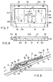
- the roofing tiles 13 adjacent in the eaves-ridge direction are continuously arranged by stacking the front hang portion 21d of the roofing tile main body 21 relatively on the ridge side on the upper surface of the upper edge portion 21c of the roofing tile main body 21 relatively on the eaves side, as shown in FIG. 5.
- the roof 12 is lapped with the roofing tiles 13.
- the output cables 47 extracted from the terminal boxes 46 are connected in series or in parallel.
- a plurality of photovoltaic modules 41 are electrically connected.
- An output terminal obtained by this connection is connected to a lead-in cable (not shown) led into the building.
- the rainwater that has entered the recess 25 runs downward on the bottom surface of the recess 25 and is discharged in the eaves direction through the drain ditches 34 and 35 formed in the front hang portion 21d of the roofing tile main body 21.
- the rainwater in the recess 25 is transferred to the upper surface of another roofing tile 13 continued on the eaves side. For this reason, even when the overlap portion between the roofing tile 13 on the eaves side and the roofing tile 13 on the ridge side is jammed with dust or the like, drainage is not impeded because that portion does not serve as a drainageway.
- the rainwater can be prevented from running into and staying in the terminal box storing recess 27. For this reason, exposure of the terminal box 46 to the rainwater staying in the storing recess 27 can be suppressed. Accordingly, corrosion of the terminal box 46, or short circuit and earth leakage at the connection portion between the terminal box 46 and the output cable 47 extracted from the terminal box 46 are suppressed. Hence, the durability of the roofing tile 13 improves.
- the photovoltaic module 41 is fixed to the roofing tile main body 21 using the fixing jigs 51 and nuts 58. Hence, the photovoltaic module 41 is firmly fixed to the roofing tile main body 21, and this fixed state is sustained for a long period. In addition, since the photovoltaic module 41 need not be fixed to the roofing tile main body 21 using an adhesive, the operation of fixing the photovoltaic module 41 to the roofing tile main body 21 is facilitated. When the photovoltaic module 41 is fixed to the roofing tile main body 21 using an adhesive, the photovoltaic module 41 may peel from the roofing tile main body 21 and drop due to degradation in adhesive. However, this problem can be solved by the roofing tile 13 with the above structure.
- the photovoltaic module 41 and fixing jigs 51 can be detached from the roofing tile main body 21.
- the fixing jigs 51 are removed from the detached photovoltaic module 41, and a new photovoltaic module 41 is set on the jigs 51.
- the new photovoltaic module 41 is stored in the recess 25 of the roofing tile main body 21 and fixed using the fixing jigs 51 and nuts 58 again. With the above operation, desired photovoltaic modules 41 can be exchanged.
- FIGS. 6 to 9 are views showing a roofing tile according to the second embodiment of the present invention.
- the second embodiment basically has the same arrangement as in the first embodiment.
- the same reference numerals as in the first embodiment denote the same parts in the second embodiment, and a detailed description of the arrangement and function will be omitted. The different points will be described below.
- the second embodiment is different from the first embodiment in the drain ditch structure, the means for fixing a photovoltaic module to a roofing tile main body, and the like.
- a single drain ditch 61 is provided.
- This drain ditch 61 is formed at a front hang portion 21d to have a length corresponding to nearly the full width of a recess 25. More specifically, the front hang portion 21d has stopper portions 62 at its two longitudinal-direction end portions.
- the single drain ditch 61 horizontally extends between the pair of stopper portion 62. For this reason, the drain ditch 61 is slightly shorter than the widthwise-direction size of the recess 25.
- the bottom surface of the drain ditch 61 continues to the bottom surface of the recess 25 essentially without forming any step and is bent downward, as in the first embodiment.
- the stopper portions 62 integrally continue to overlap portions 21a and 21b at lower corner portions 25b of the recess 25, respectively. Lower corner portions 41b of a photovoltaic module 41 are hold by the stopper portions 62, respectively. The stopper portions 62 prevent the photovoltaic module 41 stored in the recess 25 from dropping in the eaves direction.
- the reverse surface of the photovoltaic module 41 is fixed to the bottom surface of the recess 25 at a plurality of positions via an adhesive 63.
- an adhesive 63 an epoxy-, silicone-, or silicon-based adhesive can be used.
- the obverse (upper surface) of the photovoltaic module 41 fixed to the roofing tile main body 21 is almost flush with the overlap portions 21a and 21b and upper edge portion 21c around the photovoltaic module 41.
- a waterproofing gasket 64 is inserted between the edge portions of the photovoltaic module 41 and the overlap portions 21a and 21b and upper edge portion 21c.
- the photovoltaic module 41 may be fixed to the roofing tile main body 21 using a double adhesive tape instead of the adhesive 63. Alternatively, the photovoltaic module 41 may be fixed to the roofing tile main body 21 using both the double adhesive tape and the adhesive 63.
- a roofing tile 13 of the second embodiment in case of rainfall, rainwater runs from the upper surface of the photovoltaic module 41 to the drain ditch 61 and then from the drain ditch 61 to the upper surface of the photovoltaic module 41 of another roofing tile adjacent in the eaves side. Hence, normally, no rainwater enters the recess 25 of the roofing tile main body 21.
- the stopper portions 62 may be removed.
- the length of the single drain ditch 61 can be made almost equal to the full width of the recess 25, i.e., almost equal to the width of the photovoltaic module 41.
- FIGS. 10 and 11 are plan and front views showing the roofing tile main body of a roofing tile according to the third embodiment of the present invention.
- the third embodiment basically has the same arrangement as in the second embodiment.
- the same reference numerals as in the second embodiment denote the same parts in the third embodiment, and a detailed description of the arrangement and function will be omitted. The different points will be described below.
- the third embodiment is different from the second embodiment in the drain ditch, front hang portion, and the like.
- the upper-side portion of a front hang portion 21d is continuously formed without being divided at the longitudinal-direction intermediate portion.
- a pair of drain ditches 34 directly communicate with lower corner portions 25b of a recess 25, respectively.
- the drain ditches 34 obliquely extend outward from the lower corner portions 25b and cross the front hang portion 21d.
- the upper-side portion of the two end portions of the front hang portion 21d and the eaves-side end portions of overlap portions 21a and 21b are separated. Except the above-described points, the third embodiment has the same arrangement as that of the second embodiment, including structures not shown in FIGS. 10 and 11.
- FIGS. 12 and 13 are views showing a roofing tile according to the fourth embodiment of the present invention.
- the fourth embodiment basically has the same arrangement as in the second embodiment.
- the same reference numerals as in the second embodiment denote the same parts in the fourth embodiment, and a detailed description of the arrangement and function will be omitted. The different points will be described below.
- the fourth embodiment is different from the second embodiment in the drain ditch length, the photovoltaic module size, and the like.
- the width of a single drain ditch 65 formed at a front hang portion 21d of a roofing tile main body 21 is the same as the horizontal-direction width of a recess 25.
- the present invention is not limited to this, and the width of the drain ditch 65 may be larger than the width of the recess 25.
- the bottom surface of the drain ditch 65 continues to the bottom surface of the recess 25 almost without forming any step and bent downward, as in the second embodiment.
- the fourth embodiment has the same arrangement as that of the second embodiment, including structures not shown in FIGS. 12 and 13.
- the gasket (not shown) may degrade during use for a long time, and rainwater may enter the recess 25 through the degraded portion.
- the rainwater that has entered the recess 25 is discharged to the eaves side through the drain ditch 65 which is hardly jammed with dust.
- the rainwater can be suppressed from running toward a terminal box storing recess 27.
- the photovoltaic module 41 having a large power generation area can be used, the power generation efficiency can be improved.
- FIGS. 14 to 22 are views showing a power generation roofing tile according to the fifth embodiment of the present invention.
- the fifth embodiment basically has the same arrangement as in the first embodiment.
- the same reference numerals as in the first embodiment denote the same parts in the fifth embodiment, and a detailed description of the arrangement and function will be omitted. The different points will be described below.
- the fifth embodiment is different from the first embodiment in the water discharge portion, the means for fixing a photovoltaic module to a recess, and the structure of the bottom surface of the recess for efficient drainage of the recess, and the like.
- the front hang portion 21d has a pair of drain ditches 35 crossing the front hang portion 21d. As shown in FIGS. 14, 16, and 20, each drain ditch 35 has its upper surface and two ends open. A bottom surface 36 of the ditch 35 is flush with the bottom surface of a recess 25. The eaves-side end is open to the front upper surface of the front hang portion 21d (the outer end face of the front hang portion 21d).
- a thin pipe 71 is fitted on each drain ditch 35.
- the pipe 71 is obtained by cutting a plastic straw to a predetermined length.
- the inner hollow of the pipe 71 is used as a passage 71a communicating with the interior and exterior of the recess 25.
- the water discharge portion of the front hang portion 21d is basically formed from the tunnel-like passage 71a. With this water discharge portion, rainwater that has entered the recess 25 can be discharged from the passage 71a onto an eaves-side roofing tile 13 on which the front hang portion is placed.
- the recess 25 has structures shown in FIGS. 14 to 18 and FIG. 22, as will be described below. These structures fix a photovoltaic module 41 and waterproofs a terminal box 46. These structures may be omitted except the catchment ditch to be described later.
- the ends of the recess 25e are flush with the bottom surfaces of ditch portions 72a and 73a of the upper edging ditch 72 and lower edging ditch 73 along the overlap portions 21a and 21b.
- the recess 25e receives the projecting portion on the lower surface of the photovoltaic module 41, which corresponds to the output extraction line 41e.
- the box storing recess 27 is formed across the upper and lower inner portions 25c and 25d and divides the recess 25e into left and right portions.
- the bottom surface of the recess 25 has a catchment ditch 75.
- This ditch 75 has a lower ditch portion 75a and side ditch portions 75b communicating with its two ends.
- the lower ditch portion 75a extends in the widthwise direction of the roofing tile main body 21.
- This ditch portion 75a is located in the lower inner portion 25d and is slightly shorter than that.
- the lower inner portion 25d has two portions moderately tilted toward the drain ditch 35 side, and the two portions individually communicate with the drain ditches 35.
- Reference numeral 81 denotes a sealing material used as a waterproofing means.
- This sealing material 81 continuously annularly fills the entire periphery of the recess 25.
- the sealing material 81 crosses the two ends of the recess 25e at portions along the overlap portions 21a and 21b.
- the annularly coated sealing material 81 bonds the entire peripheral portion of the reverse surface of the photovoltaic module 41 stored in the recess 25.
- a part 81a of the sealing material 81 covers the upper surface of the pipe 71 to bond the pipe 71 to the inner surface of the drain ditch 35, as shown in FIG. 20.
- sealing material 81 a silicone- or silicon-based sealing material that maintains elasticity even after hardening is used.
- a polyisobutylene-based sealing material containing silicon is preferably used because it does not contaminate the surfaces of the roofing tile main body 21 and photovoltaic module 41.
- Coating of the sealing material 81 and setting of the pipe 71 are done in the following way.
- a pipe 71 longer than the drain ditch 35 is prepared, and one end portion of the pipe 71 is fitted in the drain ditch 35.
- the pipe 71 is fitted such that its end portion is located at the eaves-side ditch portion (lower ditch portion 75a) of the catchment ditch 75.
- the other end portion of the pipe 71 projects from the drain ditch 35, as indicated by the alternate long and two dashed line in FIG. 19.
- the sealing material 81 is applied around the recess 25 manually or using an automatic machine.
- the width of the recess 25 coated with the sealing material 81 is almost the same as the width of the edging ditches 72 and 73. For this reason, the applied sealing material 81 crosses the upper side portion of the drain ditch 35.
- the photovoltaic module 41 is stored in the recess 25.
- the sealing material 81 holds its shape, the projecting portion of the pipe 71 indicated by the alternate long and two dashed line in FIG. 19 is cut by a cutter. With the above procedure, the pipe 71 is mounted in the drain ditch 35.
- the tunnel-like passage may be formed in the front hang portion 21d by employing the following method, instead of leaving the pipe 71 in the drain ditch 35.
- a spacer shaft formed from a pipe or shaft longer than the drain ditch 35 is prepared. Gel-like oil is coated on the outer periphery of one end portion of the spacer shaft. This end portion with oil is fitted in the drain ditch 35.
- the sealing material 81 is applied around the recess 25 manually or using an automatic machine. After that, the photovoltaic module 41 is stored in the recess 25. Finally, after the sealing material 81 holds its shape, the spacer shaft is removed. With the above procedure, a tunnel-like passage conforming to the shape of the spacer shaft is formed between the drain ditch 35 and the drain ditch cross portion of the sealing material 81.
- the sealing material 81 is continuously annularly applied, the operation of coating the sealing material 81 need not be interrupted at the drain ditch 35. Hence, the sealing material 81 can be applied in a short time without any error, and the coating operability is high.
- Each of the adhesive ditches 80 is filled with an adhesive 83.
- the reverse surface of the photovoltaic module 41 stored in the recess 25 is bonded to the bottom surface of the recess 25 by the adhesive 83 at a plurality of portions.
- the bonding performance of the adhesive 83 is higher than that of the sealing material 81.
- an epoxy-based adhesive that maintains its elasticity in the bonded state after the start of use is preferably used. Instead, an adhesive that hardens in the bonded state after the start of use may be used.
- the fifth embodiment has the same arrangement as that of the first embodiment.
- Each adhesive 83 is provided in the internal region surrounded by the catchment ditch 75. For this reason, the adhesive 83 can be prevented from being exposed to the rainwater that has entered the recess 25 by the rainwater guiding function of the catchment ditch 75 to the above-described drain ditches 35. Hence, degradation in adhesive 83 is suppressed, and stable bonding performance is sustained for a long time.
Abstract
Description
- The present invention relates to a roofing tile used as a roofing material for a building and, more particularly, to a roofing tile having a photovoltaic module for solar-light power generation.
- A photovoltaic module for converting solar-light energy into electrical energy is known. A technique of using such a module mounted on a roofing tile used as a roofing material for a building is disclosed in, e.g., Jpn. Pat. Appln. KOKAI Publication Nos. 10-88741, 10-115051, and 10-325216.
- A photovoltaic module is fixed on a roofing tile main body by the following method. As the first fixing form, a photovoltaic module is directly bonded to the roofing tile main body with an adhesive. The second fixing form is disclosed in Jpn. Pat. Appln. KOKAI Publication No. 11-1999: a roofing tile main body having a recess is used, a photovoltaic module is bonded to the bottom surface of the recess with an adhesive, and the gap between the photovoltaic module and the inner peripheral surface of the recess is filled with a caulking material.
- However, an adhesive or caulking material readily degrades. The adhesive or caulking material rapidly degrades especially in, e.g., a rooftop environment where it is exposed to sunbeams and increases its temperature, or open to wind and rain. If the adhesive or caulking material degrades to form cracks, rainwater or dust may enter the gap between the roofing tile main body and the photovoltaic module through the cracks.
- Jpn. Pat. Appln. KOKAI Publication No. 10-88741 discloses an arrangement in which a photovoltaic module is stored in a recess of a plain roofing tile, and a through hole communicating with the reverse side of the roofing tile is formed at the eaves-side edge of the plain roofing tile. Generally, of roofing tiles adjacent in the eaves-ridge direction of a roof, the ridge-side roofing tile has its eaves-side edge portion overlapping the ridge-side edge portion of the eaves-side roofing tile. For this reason, rainwater that has entered the recess of the ridge-side roofing tile is discharged to the reverse side of the roofing tile through the through hole, is received by the eaves-side roofing tile, and runs in the eaves direction along the slope of the eaves-side roofing tile.
- The gap between the edge portions of the roofing tiles adjacent in the eaves-ridge direction is sometimes jammed with dust or the like. In this case, it is difficult for the roofing tile disclosed in Jpn. Pat. Appln. KOKAI Publication No. 10-88741 to discharge rainwater that has been discharged to the lower side of the roofing tile in the eaves direction. Accordingly, the water may be discharged to the attic side. Hence, the reliability of drainage to the eaves side is poor.
- If the through hole is jammed with dust or the like, it is hard to discharge rainwater that has entered the recess to the lower side of the roofing tile main body. When the photovoltaic module has a terminal box on its lower surface, the terminal box is exposed to the rainwater in the recess. This may cause corrosion of the terminal box or failures such as short circuit and earth leakage at the connection portion between the terminal box and an output cable extracted from the terminal box.
- In the roofing tile disclosed in Jpn. Pat. Appln. KOKAI Publication No. 10-115051, a photovoltaic module is stored in a recess. The upper surface of the eaves-side edge portion of this roofing tile is formed to be flush with that of the photovoltaic module almost without forming any step therebetween. At the left and right edge portions, the upper surface of the roofing tile projects from that of the photovoltaic module. This prior art describes the arrangement for making rainwater smoothly run on the surface of the roofing tile, though discharge of rainwater that has entered the recess of the roofing tile is not mentioned.
- In the roofing tile disclosed in. Pat. Appln. KOKAI Publication No. 10-325216, a photovoltaic module is stored in a recess. The upper surface of the eaves-side edge portion of this roofing tile is formed to be flush with that of the photovoltaic module almost without forming any step therebetween. At one of the left and right edge portions, the upper surface of the roofing tile projects from that of the photovoltaic module. This prior art describes the arrangement for making rainwater smoothly run on the surface of the roofing tile, though discharge of rainwater that has entered the recess of the roofing tile is not mentioned.
- Jpn. UM Appln. KOKAI Publication Nos. 62-52610, 1-148417, 4-28524, and 5-3430 disclose techniques of bonding a photovoltaic module to a roofing tile main body and doing waterproof treatment for the peripheral portion of the bonded photovoltaic module using a caulking material. The caulking material fills the gap between the peripheral portion of the photovoltaic module and the inner peripheral surface of the recess of the roofing tile main body in which the module is stored.
- In the roofing tile disclosed in each of these prior-art techniques, since the roofing tile main body and photovoltaic module are bonded, the roofing tile main body and photovoltaic module can hardly be separated. For a number of roofing tiles placed on a roof for solar-light power generation, a certain photovoltaic module may require exchange. In this case, only the photovoltaic module requiring exchange cannot be exchanged, and the roofing tile main body itself must be exchanged. This involves difficult operation of temporarily detaching several roofing tiles around the roofing tile to be exchanged.
- Jpn. Pat. Appln. KOKAI Publication No. 10-317592 discloses a technique of setting a roofing tile for solar-light power generation (a roofing tile with photovoltaic) using a fixing metal fitting having a clamp portion projecting from a substrate. The fixing metal fitting is fixed at the ridge-side edge portion of the roofing tile. To lap the sheathing roof board with the roofing tile by tile-roofing, the clamp portion of the fixing metal fitting is bent. The bent clamp portion clamps the eaves-side edge portion of the ridge-side roofing tile. However, the roofing tile disclosed in this prior art must be placed while bending the clamp portion of the fixing metal fitting during tile-roofing operation. Hence, laying is cumbersome, and it is difficult to firmly fix the roofing tile only by bending the clamp portion.
- It is the first object of the present invention to obtain a roofing tile having a photovoltaic module to generate power, which can discharge rainwater that has entered the recess where the photovoltaic module is stored to the eaves side at improved reliability.
- It is the second object of the present invention to obtain a roofing tile having a photovoltaic module to generate power, which can satisfactorily discharge rainwater that has entered the recess, in addition to the first object.
- It is the third object of the present invention to obtain a roofing tile having a photovoltaic module to generate power, which can suppress adverse influence on the terminal box of the photovoltaic module due to rainwater that has entered the recess, in addition to the first object of the present invention.
- It is the fourth object of the present invention to obtain a roofing tile having a photovoltaic module to generate power, which can easily exchange a photovoltaic module which requires exchange and also can firmly fix the photovoltaic module to the roofing tile main body.
- In order to achieve the first object, according to claim 1 of the present invention, there is provided a roofing tile having a photovoltaic module to generate power, which has, at the eaves-side edge portion of a roofing tile main body set tilted on a roof, at least one water discharge portion crossing the eaves-side edge portion and communicating with a recess of the roofing tile main body, in which the photovoltaic module is stored.
- In the present invention, the roofing tile main body is formed from an inorganic material such as clay, synthesis resin material, or cement, a metal material, or a composite material thereof. For the photovoltaic module, a structure can be used, in which a transparent electrode layer, a semiconductor layer for performing photoelectric conversion, and a back electrode layer are sequentially stacked, by a thin-film forming technology, on the back surface of a substrate formed from a transparent insulating material such as a transparent glass plate or transparent synthetic resin, and a protective film is coated on the lower surface. The protective layer is used for insulating, waterproofing, and mechanical protection of the layer covered with the protective layer. As the semiconductor layer, an amorphous semiconductor layer can be preferably used. However, the present invention is not limited to this, and a semiconductor layer formed from a single crystal, polycrystalline, or crystallite may be used. In addition, an Si- or compound-based material may be used. Alternatively, a tandem-type photovoltaic module may be used.
- The present invention incorporates that the water discharge portion is formed from a ditch. The present invention incorporates that the drain ditch communicates with lower corner portions of the recess. The present invention incorporates that a level of a bottom surface of the drain ditch is not more than that of a bottom surface of the recess.
- The present invention also incorporates that the water discharge portion is formed from a tunnel-like passage. The present invention incorporates that the roofing tile further comprises a sealing material continuously provided around the recess to bond a peripheral portion of the photovoltaic module to the recess, and the passage is formed between the water discharge portion and a portion of the sealing material that crosses the water discharge portion. The present invention also incorporates that the passage is formed from an inner hollow of a pipe having two open ends, the pipe being arranged between the sealing material and the water discharge portion. The present invention incorporates that the roofing tile further comprises a catchment ditch having a lower ditch portion extending in a widthwise direction of the roofing tile main body, the lower ditch portion communicating with the passage. The present invention incorporates that the catchment ditch has a pair of side ditch portions connected to two ends of the ditch portion and extending in a ridge-side edge direction of the roofing tile main body.
- According to the arrangement of the present invention, rainwater or the like that has entered the recess is discharged in the eaves direction through the water discharge portion crossing the eaves-side edge portion of the roofing tile main body. In this case, the gap between roofing tiles adjacent and overlapping in the eaves-ridge direction is not used as a drainage-way. For this reason, even when the gap is jammed with dust, drainage is not impeded. Hence, the reliability of discharge of rainwater that has entered the recess in the eaves direction improves. In addition, the rainwater that has entered the recess is not discharged to the attic side.
- In order to achieve the second object, according to
claim 3 of the present invention, there is provided a roofing tile having a photovoltaic module to generate power, characterized in that the eaves-side edge portion has a pair of stopper portions holding lower corner portions of the photovoltaic module, the drain ditch is formed between the stopper portions, and the single drain ditch has a length slightly smaller than a widthwise size of the recess. - In order to achieve the second object, according to claim 4 of the present invention, there is provided a roofing tile having a photovoltaic module to generate power, characterized in that the drain ditch is formed from a single ditch, a width of the drain ditch is not less than a widthwise size of the recess, and the recess and the drain ditch are continuous.
- According to the arrangement of this present invention, since the single drain ditch is formed widely to extend in the lateral direction of the roofing tile main body, the drain ditch is not jammed with dust. For this reason, the discharge performance for rainwater that has entered the recess in the eaves direction is maintained for a long time.
- In order to achieve the third object, according to claim 15 of the present invention, there is provided a roofing tile having a photovoltaic module to generate power, characterized in that the photovoltaic module has, on a reverse surface, a terminal box for extracting a power output from the module, and the roofing tile further comprises a terminal box storing recess formed on a bottom wall of the recess to store the box.
- According to the arrangement of this invention, since rainwater that has entered the recess is discharged in the eaves direction through the water discharge portion crossing the eaves-side edge portion of the roofing tile main body, the rainwater that has entered the recess hardly stays in the terminal box storing recess which stores the terminal box. For this reason, the terminal box can be suppressed from being exposed to rainwater in the storing recess.
- In order to achieve the fourth object, according to claim 12 of the present invention, there is provided a roofing tile having a photovoltaic module to generate power, characterized by comprising, at the eaves-side edge portion of a roofing tile main body set tilted on a roof, at least one water discharge portion crossing the eaves-side edge portion and communicating with a recess of the roofing tile main body, in which the photovoltaic module is stored, wherein the photovoltaic module is fixed to the roofing tile main body through a fixing jig and nut. The fixing jig has a first end portion having a bent piece overlapping an upper surface of an edge portion of the photovoltaic module and holding the edge portion of the module, and a second end portion to which a bolt extending through the through hole is fixed. The fixing jig is fixed to the roofing tile main body by tightening the detachable nut on the bolt on the reverse side of the roofing tile main body.
- The present invention incorporate that the first end portion is holding an eaves-side edge portion of the photovoltaic module. The present invention also incorporates that a levee is formed on the bottom surface of the recess so as to continuously surround a ridge side and left and right sides of the through hole.
- According to the arrangement of this invention, when the nut is tightened, the photovoltaic module is pressed against the recess of the roofing tile main body through the fixing jig, and fixed to the roofing tile main body. When the nut is loosened and detached, the photovoltaic module and fixing jig can be detached from the roofing tile main body. Hence, the standalone photovoltaic module can be exchanged. In addition, according to the arrangement having the levee, rainwater that has entered the recess can be prevented by the levee from running into the through hole.
- This summary of the invention does not necessarily describe all necessary features so that the invention may also be a sub-combination of these described features.
- The invention can be more fully under stood from the following detailed description when taken in conjunction with the accompanying drawings, in which:
- FIG. 1 is an exploded perspective view showing a roofing tile according to the first embodiment of the present invention;
- FIG. 2 is a plan view showing the roofing tile main body of the roofing tile according to the first embodiment;
- FIG. 3 is a sectional view of the roofing tile according to the first embodiment;
- FIG. 4 is a perspective view schematically showing a building having a roof covered with the roofing tiles according to the first embodiment;
- FIG. 5 is a sectional view showing part of the roof of the building shown in FIG. 4;
- FIG. 6 is an exploded perspective view showing a roofing tile according to the second embodiment of the present invention;
- FIG. 7 is a plan view showing the roofing tile main body of the roofing tile according to the second embodiment;
- FIG. 8 is a front view of the roofing tile according to the second embodiment;
- FIG. 9 is a sectional view showing part of the roof of a building roofed with the roofing tile according to the second embodiment;
- FIG. 10 is a plan view showing the roofing tile main body of a roofing tile according to the third embodiment of the present invention;
- FIG. 11 is a front view of the roofing tile according to the third embodiment;
- FIG. 12 is a plan view showing the roofing tile main body of a roofing tile according to the fourth embodiment of the present invention;
- FIG. 13 is a front view of the roofing tile according to the fourth embodiment;
- FIG. 14 is an exploded perspective view showing a roofing tile according to the fifth embodiment of the present invention;
- FIG. 15 is a plan view showing the roofing tile main body of the roofing tile according to the fifth embodiment;
- FIG. 16 is a front view showing the roofing tile main body of the roofing tile according to the fifth embodiment;
- FIG. 17 is a sectional view of the roofing tile according to the fifth embodiment;
- FIG. 18 is an enlarged sectional view showing a portion F18 shown in FIG. 17;
- FIG. 19 is a sectional view showing the drain ditch portion of the roofing tile according to the fifth embodiment;
- FIG. 20 is a front view showing the drain ditch portion shown in FIG. 19 before a photovoltaic module is mounted;
- FIG. 21 is a plan view showing the drain ditch portion shown in FIG. 19 before a photovoltaic module is mounted; and
- FIG. 22 is a sectional view showing the roofing tile according to the fifth embodiment, which is taken along a line F21 - F21 in FIG. 15.
-
- The first embodiment of the present invention will be described below with reference to FIGS. 1 to 5.
- FIG. 4 is a perspective view schematically showing a building having a roof covered with roofing tiles according to the first embodiment. A
roof 12 of abuilding 11 has a number ofroofing tile 13 as a roofing material. Theroofing tiles 13 are arranged in order in the vertical and horizontal directions. Eachroofing tile 13 obtains electrical energy by solar-light power generation. Anarrow 14 in FIGS. 1, 4, and 5 indicates the eaves direction, and anarrow 15 indicates the ridge direction. Referring to FIG. 5,reference numeral 16 denotes a sheathing roof board of theroof 12, which tilts downward from the ridge side to the eaves side of theroof 12. - As shown in FIGS. 1 and 3, each
roofing tile 13 has a roofing tilemain body 21,photovoltaic module 41, a plurality of, e.g., two fixingjigs 51, andnuts 58 equal in number to thejigs 51. - As shown in FIGS. 1 and 2, the roofing tile
main body 21 is formed from, e.g., cement into an almost rectangle flat plate. The roofing tilemain body 21 has, at its two side portions in the width direction,overlap portions 21a and 21b as left and right side portions. Theoverlap portions 21a and 21b engage with the overlap portions of adjacent roofing tilemain bodies 21 on the left and right sides on theroof 12. An upper edge portion 21c as the ridge-side edge portion of the roofing tilemain body 21 has an upright portion 21cu. The lower edge portion as the eaves-side edge portion of the roofing tilemain body 21 forms afront hang portion 21d. As shown in FIG. 3, thefront hang portion 21d is bent downward. Theoverlap portions 21a and 21b and upper edge portion 21c continue. In this embodiment, theoverlap portions 21a and 21b andfront hang portion 21d do not continue. - As shown in FIG. 5, the roofing tile
main bodies 21 adjacent in the vertical direction (eaves-ridge direction) continuously overlap on theroof 12. More specifically, thefront hang portion 21d of the ridge-side roofing tilemain body 21 relatively located on the upstream side overlaps the upper surface of the upper edge portion 21c of the eaves-side roofing tilemain body 21 relatively located on the downstream side. Each roofing tilemain body 21 is placed on thesheathing roof board 16 directly or via an underlying roofing material such as roofing (not shown). Referring to FIGS. 1 and 2,reference numerals 23 denote fixing holes each of which receives a tile attachment component such as a nail or screw to fix the roofing tilemain body 21. - The roofing tile
main body 21 has arectangular recess 25 open upward. Therecess 25 has a size corresponding to the most part of the roofing tilemain body 21. Therecess 25 is surrounded by the edge portions of the roofing tilemain body 21, i.e., theoverlap portions 21a and 21b, upper edge portion 21c, andfront hang portion 21d. The depth of therecess 25 is slightly larger than the thickness of thephotovoltaic module 41. - The
recess 25 has a terminalbox storing recess 27 at the central portion in the width direction of a bottom wall 25a. This storingrecess 27 has a rectangular planar shape and extends in the eaves-ridge direction. The reverse surface of the terminalbox storing recess 27 is almost flush with thefront hang portion 21d of the roofing tilemain body 21. Thus, the roofing tilemain body 21 is stably placed on theroof 12. - A
cable leading hole 28 is formed in the bottom plate portion of the terminalbox storing recess 27. The leadinghole 28 is located on the upper side of the intermediate point of therecess 25 in the eaves-ridge direction. Hence, thecable leading hole 28 is located on the upper side of therecess 25, i.e., on the ridge side. - As shown in FIGS. 1 and 2, the bottom wall 25a of the
recess 25 has at least one and, for example, a pair of throughholes 29 extending through itself. Theseholes 29 are formed on both sides of the terminalbox storing recess 27. The through holes 29 are preferably formed on the ridge side of therecess 25, like thecable leading hole 28. With this arrangement, even if the mount of rainwater entering therecess 25 is larger than the discharge amount from therecess 25 through drain ditches (to be described later), the water level in therecess 25 can be prevented from reaching the through holes 29. -
Levees 31 are integrally formed near the throughholes 29 on the upper surface of the bottom wall 25a of therecess 25. Eachlevee 31 continuously surrounds a corresponding throughhole 29 on its upper (ridge) side, and left and right sides. Thelevees 31 are open on the eaves side. Thelevees 31 prevent rainwater that has entered therecess 25 from reaching the through holes 29. For this reason, rainwater leakage to the reverse side of the roofing tilemain body 21 can be prevented. - As shown in FIGS. 1 and 2, the
front hang portion 21d of the roofing tilemain body 21 has a pair of first drain ditches 34 and a pair of second drain ditches 35, each of which serves as a water discharge portion. Rainwater that has entered therecess 25 is discharged to the eaves side through the drain ditches 34 and 35. The pair of first drain ditches 34 cross, in the eaves-ridge direction, the upper side portion of thefront hang portion 21d at its two longitudinal-direction end portions, thereby separating theoverlap portions 21a and 21b from the upper side portion of thefront hang portion 21d. The pair of second drain ditches 35 cross, in the eaves-ridge direction, the upper side portion of thefront hang portion 21d at its longitudinal-direction intermediate portion, thereby dividing the upper side portion of thefront hang portion 21d into a plurality of parts. - The ridge-side ends of the two first drain ditches 34 communicate with
lower corner portions 25b of therecess 25. The ridge-side ends of the two second drain ditches 35 communicate with the widthwise-direction intermediate portion of therecess 25. These drain ditches 34 and 35 are formed along the curve of thefront hang portion 21d and open to the upper surface of thefront hang portion 21d. The eaves-side ends of the drain ditches 34 and 35 reach an end face 21de of thefront hang portion 21d and are open. - Bottom surfaces 36 (represented by FIG. 3) of the drain ditches 34 and 35 are lower than the bottom surface of the
recess 25, i.e., the upper surface of the bottom wall 25a. In this embodiment, the bottom surfaces 36 are curved. The upper portions of the bottom surfaces 36 continue to the upper surface of the bottom wall 25a almost without forming any step, and the bottom surfaces 36 gradually lower toward the end face 21de. - In the present invention, instead of curving the
bottom surface 36, it may have a step lower then the upper surface of the bottom wall 25a. Thebottom surface 36 may be flush with the upper surface of the bottom wall 25a. Thebottom surface 36 may tilt downward from the upper surface of the bottom wall 25a. Hence, in the present invention, the eaves-side ends of the drain ditches 34 and 35 are open to the eaves-side surface of thefront hang portion 21d in the eaves direction without reaching the end face 21de. - The
recess 25 of the roofing tilemain body 21 has a size suitable to the size of thephotovoltaic module 41. Thephotovoltaic module 41 is stored in therecess 25 and fixed as will be described later. - The
photovoltaic module 41 shown in FIG. 1 has a rectangular modulemain body 45 andterminal box 46. The surface of the modulemain body 45 serves as a light incident surface. Theterminal box 46 is bonded to at almost the widthwise-direction central portion of the reverse surface of the modulemain body 45. As shown in FIG. 5, anoutput cable 47 is extracted from theterminal box 46. - The module
main body 45 has a thin panel-like shape and comprises a transparent substrate made of glass, a plurality of amorphous silicon cells serving as a semiconductor layer, a pair of positive and negative electrodes, a pair of output extraction lines, and a protective layer (none are shown). The cells are formed on the reverse surface of the transparent substrate and connected in series for solar heat power generation by photoelectric conversion. The positive and negative electrodes are arranged on both sides of the cell group and electrically connected to the cell group. The pair of output extraction lines electrically connect the positive and negative electrodes to the terminal box. The protective layer has a filling material which is stacked on the lower side of the transparent substrate and seals the greater part of the output extraction lines, the cells, and the electrodes, and a protective sheet adhered to the filling material. - The cells and electrodes extend parallel to each other and in the eaves-ridge direction of the
roof 12. The output extraction lines are perpendicularly connected to the electrodes and extend in the widthwise direction of the modulemain body 45. The distal end portions of the output extraction lines are bent toward the reverse side, extend through the protective layer, and are connected, in theterminal box 46, to terminal metal fittings (not shown) of thebox 46. - As shown in FIGS. 1 and 3, the
photovoltaic module 41 is fixed in therecess 25 of the roofing tilemain body 21 using the fixingjigs 51 and nuts 58. Each fixingjig 51 is mainly formed from, e.g., along metal plate 52 and has afirst end portion 53 andsecond end portion 54. - The
first end portion 53 is formed by bending one end portion of themetal plate 52 upward and then toward thesecond end portion 54. A bent piece 53a bent to thesecond end portion 54 side is almost parallel to themetal plate 52. The bent piece 53a is stacked on the upper surface of the edge portion of the modulemain body 45. The edge portion of the modulemain body 45 can be inserted/removed into/from the inner space surrounded by thefirst end portion 53. - One
bolt 55 is welded to the lower surface of thesecond end portion 54. Thebolt 55 need not always be fixed to themetal plate 52 by welding. For example, thebolt 55 may be inserted into a hole formed in themetal plate 52 and fixed by arranging nuts (not shown) on the upper and lower sides of themetal plate 52 and threadably engaging them with thebolt 55. When thebolt 55 is fixed by welding, it can be fixed without making itself and a nut project from the upper surface of themetal plate 52. This structure is advantageous because the bolt and the like can be prevented from locally abutting against the reverse surface of the modulemain body 45 and exerting a load on the modulemain body 45. Thebolts 55 can project to the reverse side of the bottom wall 25a of therecess 25 through the through holes 29. - A plurality of
bolts 55, e.g., twobolts 55 may be used in accordance with the size of the modulemain body 45. In this case, onebolt 55 is fixed to thesecond end portion 54, and theother bolt 55 can be fixed to an arbitrary portion. In this arrangement, the number of throughholes 29 of therecess 25 is also increased. - Each fixing
jig 51 is arranged on the reverse side of the modulemain body 45 while holding thefirst end portion 53 on a lower edge portion 45a of themain body 45. The assembly of the fixingjigs 51 andphotovoltaic module 41 is stored in therecess 25. To store the assembly, thebolt 55 of each fixingjig 51 is inserted into a corresponding one of the through holes 29. On the reverse side of the roofing tilemain body 21, thenuts 58 threadably engage with thebolts 55 extending through the throughholes 29, respectively. When the nuts 58 are tightened, thephotovoltaic module 41 stored in therecess 25 is fixed to the roofing tilemain body 21. The nuts 58 can be detached from thebolts 55. When the nuts 58 are loosened and detached from thebolts 55, thephotovoltaic module 41 can be easily detached from the roofing tilemain body 21. - After tightening the nuts 58, the through
holes 29 are sealed using a sealing material (not shown). This sealing is preferable because rainwater that has entered therecess 25 can be prevented from leaking to the reverse side of the roofing tilemain body 21. In fixing thephotovoltaic module 41, it is preferable to bring the upright portion 53a of thefirst end portion 53 into contact with thefront hang portion 21d of the roofing tilemain body 21. - To fix one
photovoltaic module 41 to the roofing tilemain body 21, at least two fixingjigs 51 need be used. For fixing, each fixingjig 51 is set along the vertical direction of therecess 25 and has itsfirst end portion 53 holding the lower edge portion 45a of the modulemain body 45. Thefirst end portion 53 that presses the edge portion of thephotovoltaic module 41 from the upper side can be used as a stopper for preventing thephotovoltaic module 41 from dropping. - The fixing
jig 51 may be set along the horizontal direction (widthwise direction) of therecess 25 and have itsfirst end portion 53 holding one side edge portion 41c of the modulemain body 45. This can be implemented by partially omitting thelevee 31, i.e., omitting the portion almost parallel to the side edge portion 41c of the modulemain body 45. When the fixingjig 51 is arranged in the widthwise direction, itsfirst end portion 53 can be located obliquely on the lower side of a horizontal line passing through the throughhole 29. This arrangement is preferable because rainwater can be prevented from reaching the throughhole 29 along the fixingjig 51. - When the
photovoltaic module 41 is fixed in therecess 25, theterminal box 46 on the reverse surface of themodule 41 is stored in the terminalbox storing recess 27 of therecess 25. As shown in FIG. 5, theoutput cable 47 connected to theterminal box 46 is extracted to the reverse side of the roofing tilemain body 21 through thecable leading hole 28 of the storingrecess 27. - In operation of lapping the
roof 12 with theroofing tiles 13 each having the above structure by mounting theroofing tiles 13 on thesheathing roof board 16, theroofing tiles 13 are mounted on thesheathing roof board 16 from the eaves side to the ridge side and fixed on thesheathing roof board 16 by inserting nails or the like into the fixing holes 23, as in the normal tile-roofing operation. In this case, theroofing tiles 13 adjacent in the horizontal direction are continuously arranged by fitting and overlapping theoverlap portions 21a and 21b of the roofing tilemain bodies 21 to each other. Theroofing tiles 13 adjacent in the eaves-ridge direction are continuously arranged by stacking thefront hang portion 21d of the roofing tilemain body 21 relatively on the ridge side on the upper surface of the upper edge portion 21c of the roofing tilemain body 21 relatively on the eaves side, as shown in FIG. 5. - By repeating this operation, the
roof 12 is lapped with theroofing tiles 13. Parallel to this tile-roofing operation, theoutput cables 47 extracted from theterminal boxes 46 are connected in series or in parallel. Thus, a plurality ofphotovoltaic modules 41 are electrically connected. An output terminal obtained by this connection is connected to a lead-in cable (not shown) led into the building. - In case of rainfall, rainwater hitting the upper surface of the
photovoltaic module 41 runs downward on the upper surface of themodule 41, continuously on the upper surface of thefront hang portion 21d of the roofing tilemain body 21, and then to the upper surface of anotherroofing tile 13 continued on the eaves side. Part of the rainwater poured onto theroofing tile 13 enters therecess 25 through the gaps between theoverlap portions 21a and 21b of the roofing tilemain body 21 and the side edge portions of thephotovoltaic module 41. - The rainwater that has entered the
recess 25 runs downward on the bottom surface of therecess 25 and is discharged in the eaves direction through the drain ditches 34 and 35 formed in thefront hang portion 21d of the roofing tilemain body 21. Thus, the rainwater in therecess 25 is transferred to the upper surface of anotherroofing tile 13 continued on the eaves side. For this reason, even when the overlap portion between theroofing tile 13 on the eaves side and theroofing tile 13 on the ridge side is jammed with dust or the like, drainage is not impeded because that portion does not serve as a drainageway. - As described above, the rainwater that has entered the
recess 25 runs downward on the upper surface side of thefront hang portion 21d along the tiltedroofing tile 13 through the drain ditches 34 and 35 located on the upper side of the overlap portion. Hence, the water can be reliably discharged. In addition, the water discharge portion is formed from the drain ditches 34 and 35 each having an upper surface and two end portions open and is hardly jammed with dust or the like, as compared to a hole. This structure can be suitably employed to maintain the above-described drainage performance. - Furthermore, since the rainwater in the
recess 25 is discharged to the eaves side without being discharged to the reverse side of the roofing tilemain body 21, as described above, thesheathing roof board 16 does not get wet. - Most part of the rainwater that has entered the
recess 25 tends to run downward along theoverlap portions 21a and 21b along the gaps as inlets and reach thelower corner portions 25b of therecess 25. The pair of first drain ditches 34 of theroofing tile 13 with the above arrangement directly communicate with thelower corner portions 25b of therecess 25. For this reason, the water can be easily discharged through theditches 34. - With the above drainage, the rainwater can be prevented from running into and staying in the terminal
box storing recess 27. For this reason, exposure of theterminal box 46 to the rainwater staying in the storingrecess 27 can be suppressed. Accordingly, corrosion of theterminal box 46, or short circuit and earth leakage at the connection portion between theterminal box 46 and theoutput cable 47 extracted from theterminal box 46 are suppressed. Hence, the durability of theroofing tile 13 improves. - According to the
roofing tile 13 having the above structure, thephotovoltaic module 41 is fixed to the roofing tilemain body 21 using the fixingjigs 51 and nuts 58. Hence, thephotovoltaic module 41 is firmly fixed to the roofing tilemain body 21, and this fixed state is sustained for a long period. In addition, since thephotovoltaic module 41 need not be fixed to the roofing tilemain body 21 using an adhesive, the operation of fixing thephotovoltaic module 41 to the roofing tilemain body 21 is facilitated. When thephotovoltaic module 41 is fixed to the roofing tilemain body 21 using an adhesive, thephotovoltaic module 41 may peel from the roofing tilemain body 21 and drop due to degradation in adhesive. However, this problem can be solved by theroofing tile 13 with the above structure. - One or more of
photovoltaic modules 41 placed on theroof 12 together with the roofing tilemain bodies 21 may be damaged and require exchange. In this case, only thephotovoltaic modules 41 which must be exchanged can be exchanged with newphotovoltaic modules 41. This is because the fixingjigs 51 andnuts 58 that fix thephotovoltaic module 41 to the roofing tilemain body 21 can be detached. - When the nuts 58 that fix the
photovoltaic module 41 requiring exchange are loosened and detached from thebolts 55 of the fixingjigs 51, thephotovoltaic module 41 and fixingjigs 51 can be detached from the roofing tilemain body 21. After that, the fixingjigs 51 are removed from the detachedphotovoltaic module 41, and a newphotovoltaic module 41 is set on thejigs 51. The newphotovoltaic module 41 is stored in therecess 25 of the roofing tilemain body 21 and fixed using the fixingjigs 51 andnuts 58 again. With the above operation, desiredphotovoltaic modules 41 can be exchanged. - FIGS. 6 to 9 are views showing a roofing tile according to the second embodiment of the present invention. The second embodiment basically has the same arrangement as in the first embodiment. The same reference numerals as in the first embodiment denote the same parts in the second embodiment, and a detailed description of the arrangement and function will be omitted. The different points will be described below. The second embodiment is different from the first embodiment in the drain ditch structure, the means for fixing a photovoltaic module to a roofing tile main body, and the like.
- In the second embodiment, a
single drain ditch 61 is provided. Thisdrain ditch 61 is formed at afront hang portion 21d to have a length corresponding to nearly the full width of arecess 25. More specifically, thefront hang portion 21d hasstopper portions 62 at its two longitudinal-direction end portions. Thesingle drain ditch 61 horizontally extends between the pair ofstopper portion 62. For this reason, thedrain ditch 61 is slightly shorter than the widthwise-direction size of therecess 25. The bottom surface of thedrain ditch 61 continues to the bottom surface of therecess 25 essentially without forming any step and is bent downward, as in the first embodiment. - The
stopper portions 62 integrally continue to overlapportions 21a and 21b atlower corner portions 25b of therecess 25, respectively.Lower corner portions 41b of aphotovoltaic module 41 are hold by thestopper portions 62, respectively. Thestopper portions 62 prevent thephotovoltaic module 41 stored in therecess 25 from dropping in the eaves direction. - The reverse surface of the
photovoltaic module 41 is fixed to the bottom surface of therecess 25 at a plurality of positions via an adhesive 63. As the adhesive 63, an epoxy-, silicone-, or silicon-based adhesive can be used. The obverse (upper surface) of thephotovoltaic module 41 fixed to the roofing tilemain body 21 is almost flush with theoverlap portions 21a and 21b and upper edge portion 21c around thephotovoltaic module 41. Awaterproofing gasket 64 is inserted between the edge portions of thephotovoltaic module 41 and theoverlap portions 21a and 21b and upper edge portion 21c. - The
photovoltaic module 41 may be fixed to the roofing tilemain body 21 using a double adhesive tape instead of the adhesive 63. Alternatively, thephotovoltaic module 41 may be fixed to the roofing tilemain body 21 using both the double adhesive tape and the adhesive 63. - Except the above-described points, the second embodiment has the same arrangement as that of the first embodiment, including structures not shown in FIGS. 6 to 9.
- According to the structure of a
roofing tile 13 of the second embodiment, in case of rainfall, rainwater runs from the upper surface of thephotovoltaic module 41 to thedrain ditch 61 and then from thedrain ditch 61 to the upper surface of thephotovoltaic module 41 of another roofing tile adjacent in the eaves side. Hence, normally, no rainwater enters therecess 25 of the roofing tilemain body 21. - However, when the roofing tile is exposed to sunbeams or wind and rain for a long time, and the
gasket 64 degrades, rainwater may enter therecess 25 through the degraded portion. In this case, the rainwater that has entered therecess 25 is easily discharged through thedrain ditch 61 having almost the same length as that of thefront hang portion 21d of the roofing tilemain body 21. Hence, rainwater can be suppressed from running toward a terminalbox storing recess 27. - In addition, since the
drain ditch 61 is formed virtually in correspondence with the full width of therecess 25, thedrain ditch 61 is not completely jammed with dust or the like. Hence, the drainage reliability is high, and the drainage performance for discharging rainwater that has entered the gap between the roofing tilemain body 21 and thephotovoltaic module 41 to the eaves side can be maintained for a long period. - In the second embodiment, the
stopper portions 62 may be removed. In this case, the length of thesingle drain ditch 61 can be made almost equal to the full width of therecess 25, i.e., almost equal to the width of thephotovoltaic module 41. - FIGS. 10 and 11 are plan and front views showing the roofing tile main body of a roofing tile according to the third embodiment of the present invention. The third embodiment basically has the same arrangement as in the second embodiment. The same reference numerals as in the second embodiment denote the same parts in the third embodiment, and a detailed description of the arrangement and function will be omitted. The different points will be described below. The third embodiment is different from the second embodiment in the drain ditch, front hang portion, and the like.
- In the third embodiment, the upper-side portion of a
front hang portion 21d is continuously formed without being divided at the longitudinal-direction intermediate portion. A pair of drain ditches 34 directly communicate withlower corner portions 25b of arecess 25, respectively. The drain ditches 34 obliquely extend outward from thelower corner portions 25b and cross thefront hang portion 21d. The upper-side portion of the two end portions of thefront hang portion 21d and the eaves-side end portions ofoverlap portions 21a and 21b are separated. Except the above-described points, the third embodiment has the same arrangement as that of the second embodiment, including structures not shown in FIGS. 10 and 11. - In the arrangement of the roofing tile according to the third embodiment as well, the gasket (not shown) may degrade during use for a long time, and rainwater may enter the
recess 25 through the degraded portion. In this case, the rainwater that has entered therecess 25 is discharged to the eaves side through the pair of drain ditches 34 of the roofing tilemain body 21. Hence, the rainwater can be suppressed from running toward a terminalbox storing recess 27. - FIGS. 12 and 13 are views showing a roofing tile according to the fourth embodiment of the present invention. The fourth embodiment basically has the same arrangement as in the second embodiment. The same reference numerals as in the second embodiment denote the same parts in the fourth embodiment, and a detailed description of the arrangement and function will be omitted. The different points will be described below. The fourth embodiment is different from the second embodiment in the drain ditch length, the photovoltaic module size, and the like.
- In the fourth embodiment, the width of a single drain ditch 65 formed at a
front hang portion 21d of a roofing tilemain body 21 is the same as the horizontal-direction width of arecess 25. The present invention is not limited to this, and the width of the drain ditch 65 may be larger than the width of therecess 25. The bottom surface of the drain ditch 65 continues to the bottom surface of therecess 25 almost without forming any step and bent downward, as in the second embodiment. - The size (depth direction) of a
photovoltaic module 41 stored in therecess 25 is larger than that of themodule 41 of the second embodiment. A lower edge portion 41a of thephotovoltaic module 41 opposes and covers the most part of the drain ditch 65 from the upper side. Hence, thephotovoltaic module 41 of the fourth embodiment is larger than that of the second embodiment. - Except the above-described points, the fourth embodiment has the same arrangement as that of the second embodiment, including structures not shown in FIGS. 12 and 13.
- In the arrangement of the roofing tile according to the fourth embodiment as well, the gasket (not shown) may degrade during use for a long time, and rainwater may enter the
recess 25 through the degraded portion. In this case, the rainwater that has entered therecess 25 is discharged to the eaves side through the drain ditch 65 which is hardly jammed with dust. Hence, the rainwater can be suppressed from running toward a terminalbox storing recess 27. Additionally, since thephotovoltaic module 41 having a large power generation area can be used, the power generation efficiency can be improved. - FIGS. 14 to 22 are views showing a power generation roofing tile according to the fifth embodiment of the present invention. The fifth embodiment basically has the same arrangement as in the first embodiment. The same reference numerals as in the first embodiment denote the same parts in the fifth embodiment, and a detailed description of the arrangement and function will be omitted. The different points will be described below. The fifth embodiment is different from the first embodiment in the water discharge portion, the means for fixing a photovoltaic module to a recess, and the structure of the bottom surface of the recess for efficient drainage of the recess, and the like.
- Referring to FIG. 14, reference numerals 41a to 41c denote constituent members of the module main body. These members have already been described in the first embodiment. Reference numeral 41c denotes a transparent glass substrate; 41d, electrodes; and 41e, an output extraction line.
- The two longitudinal-direction ends of a
front hang portion 21d of a roofing tilemain body 21 integrally continue to overlapportions 21a and 21b, respectively. Thefront hang portion 21d has a pair of drain ditches 35 crossing thefront hang portion 21d. As shown in FIGS. 14, 16, and 20, eachdrain ditch 35 has its upper surface and two ends open. Abottom surface 36 of theditch 35 is flush with the bottom surface of arecess 25. The eaves-side end is open to the front upper surface of thefront hang portion 21d (the outer end face of thefront hang portion 21d). - A
thin pipe 71 is fitted on eachdrain ditch 35. Thepipe 71 is obtained by cutting a plastic straw to a predetermined length. The inner hollow of thepipe 71 is used as a passage 71a communicating with the interior and exterior of therecess 25. Hence, the water discharge portion of thefront hang portion 21d is basically formed from the tunnel-like passage 71a. With this water discharge portion, rainwater that has entered therecess 25 can be discharged from the passage 71a onto an eaves-side roofing tile 13 on which the front hang portion is placed. - The
recess 25 has structures shown in FIGS. 14 to 18 and FIG. 22, as will be described below. These structures fix aphotovoltaic module 41 and waterproofs aterminal box 46. These structures may be omitted except the catchment ditch to be described later. - The
recess 25 has, on its bottom surface, anupper edging ditch 72 andlower edging ditch 73, which are spaced apart from each other in the vertical direction. Theupper edging ditch 72 is continuously formed along the upper portions of an upper edge portion 21c andoverlap portions 21a and 21b. Thelower edging ditch 73 is continuously formed along the lower portions of thefront hang portion 21d andoverlap portions 21a and 21b. Thelower edging ditch 73 along thefront hang portion 21d has discontinuous parts at the positions of the pair of drain ditches 35, as shown in FIG. 15. The drain ditches 35 andpipes 71 cross the discontinuous portions. - The bottom surface of the
recess 25 has an upperinner portion 25c, lowerinner portion 25d, andshallow recess 25e formed between theportions inner portion 25c is surrounded by the upper edging ditch 72f from three directions. The lowerinner portion 25d is surrounded by thelower edging ditch 73 from three directions. Therecess 25e extends in the widthwise direction of therecess 25. - The ends of the
recess 25e are flush with the bottom surfaces of ditch portions 72a and 73a of theupper edging ditch 72 andlower edging ditch 73 along theoverlap portions 21a and 21b. Therecess 25e receives the projecting portion on the lower surface of thephotovoltaic module 41, which corresponds to the output extraction line 41e. Thebox storing recess 27 is formed across the upper and lowerinner portions recess 25e into left and right portions. - The bottom surface of the
recess 25 has acatchment ditch 75. Thisditch 75 has a lower ditch portion 75a andside ditch portions 75b communicating with its two ends. The lower ditch portion 75a extends in the widthwise direction of the roofing tilemain body 21. This ditch portion 75a is located in the lowerinner portion 25d and is slightly shorter than that. The lowerinner portion 25d has two portions moderately tilted toward thedrain ditch 35 side, and the two portions individually communicate with the drain ditches 35. - The pair of
side ditch portions 75b is formed across the upper and lowerinner portions overlap portions 21a and 21b while crossing therecess 25e. Thecatchment ditch 75 has anupper ditch portion 75c bent from the twoside ditch portions 75b toward the terminalbox storing recess 27. Hence, thecatchment ditch 75 almost continuously surrounds thebox storing recess 27. - The bottom surface of the
recess 25 has anannular ditch 77 located inside thecatchment ditch 75. Thisditch 77 continuously surrounds thebox storing recess 27. Theupper ditch portion 75c is connected to the two ends of the upper end portion of theannular ditch 77.Partitions 78 are formed at the connection portions. Rainwater may be blown into thecatchment ditch 75 through the drain ditches 35. Thepartitions 78 prevent the blown rainwater from running back to theannular ditch 77 and finally reaching thebox storing recess 27. - At least one
adhesive ditch 80 is formed on the bottom surface of therecess 25 at a portion surrounded by thecatchment ditch 75. More specifically, twoadhesive ditches 80 are formed in each of a region between the overlap portion 21a and thebox storing recess 27 and a region between theoverlap portion 21b and thebox storing recess 27. Theseadhesive ditches 80 extend in the vertical direction (eaves-ridge direction) across the upperinner portion 25c andrecess 25e. - The
photovoltaic module 41 is stored and fixed in therecess 25 having the above structure by the following way.Reference numeral 81 denotes a sealing material used as a waterproofing means. This sealingmaterial 81 continuously annularly fills the entire periphery of therecess 25. The sealingmaterial 81 crosses the two ends of therecess 25e at portions along theoverlap portions 21a and 21b. The annularly coated sealingmaterial 81 bonds the entire peripheral portion of the reverse surface of thephotovoltaic module 41 stored in therecess 25. In addition, a part 81a of the sealingmaterial 81 covers the upper surface of thepipe 71 to bond thepipe 71 to the inner surface of thedrain ditch 35, as shown in FIG. 20. - As the sealing
material 81, a silicone- or silicon-based sealing material that maintains elasticity even after hardening is used. Especially, a polyisobutylene-based sealing material containing silicon is preferably used because it does not contaminate the surfaces of the roofing tilemain body 21 andphotovoltaic module 41. - Coating of the sealing
material 81 and setting of thepipe 71 are done in the following way. First, apipe 71 longer than thedrain ditch 35 is prepared, and one end portion of thepipe 71 is fitted in thedrain ditch 35. In this case, thepipe 71 is fitted such that its end portion is located at the eaves-side ditch portion (lower ditch portion 75a) of thecatchment ditch 75. When thepipe 71 is completely fitted, the other end portion of thepipe 71 projects from thedrain ditch 35, as indicated by the alternate long and two dashed line in FIG. 19. - Next, the sealing
material 81 is applied around therecess 25 manually or using an automatic machine. The width of therecess 25 coated with the sealingmaterial 81 is almost the same as the width of the edging ditches 72 and 73. For this reason, the applied sealingmaterial 81 crosses the upper side portion of thedrain ditch 35. - Finally, after an adhesive (to be described later) is applied, the
photovoltaic module 41 is stored in therecess 25. After or before the sealingmaterial 81 holds its shape, the projecting portion of thepipe 71 indicated by the alternate long and two dashed line in FIG. 19 is cut by a cutter. With the above procedure, thepipe 71 is mounted in thedrain ditch 35. - The tunnel-like passage may be formed in the
front hang portion 21d by employing the following method, instead of leaving thepipe 71 in thedrain ditch 35. First, a spacer shaft formed from a pipe or shaft longer than thedrain ditch 35 is prepared. Gel-like oil is coated on the outer periphery of one end portion of the spacer shaft. This end portion with oil is fitted in thedrain ditch 35. Next, the sealingmaterial 81 is applied around therecess 25 manually or using an automatic machine. After that, thephotovoltaic module 41 is stored in therecess 25. Finally, after the sealingmaterial 81 holds its shape, the spacer shaft is removed. With the above procedure, a tunnel-like passage conforming to the shape of the spacer shaft is formed between thedrain ditch 35 and the drain ditch cross portion of the sealingmaterial 81. - As described above, since the sealing
material 81 is continuously annularly applied, the operation of coating the sealingmaterial 81 need not be interrupted at thedrain ditch 35. Hence, the sealingmaterial 81 can be applied in a short time without any error, and the coating operability is high. - Each of the
adhesive ditches 80 is filled with an adhesive 83. The reverse surface of thephotovoltaic module 41 stored in therecess 25 is bonded to the bottom surface of therecess 25 by the adhesive 83 at a plurality of portions. The bonding performance of the adhesive 83 is higher than that of the sealingmaterial 81. As the adhesive 83, an epoxy-based adhesive that maintains its elasticity in the bonded state after the start of use is preferably used. Instead, an adhesive that hardens in the bonded state after the start of use may be used. - As described above, the
photovoltaic module 41 is bonded using both the sealingmaterial 81 having an adhesion and the adhesive 83 having a higher bonding strength. For this reason, thephotovoltaic module 41 can be firmly fixed to therecess 25. - The slightly projecting portion which covers the output extraction line 41e on the reverse surface of the
photovoltaic module 41 is stored in therecess 25e. For this reason, thephotovoltaic module 41 is arranged in an appropriate posture without being slightly tilted from the projecting portion as a fulcrum. Since the flat reverse surface of thephotovoltaic module 41 comes into surface contact with the upper and lowerinner portions material 81 and adhesive 83 readily becomes uniform for the respective portions. Hence, the sealingmaterial 81 can exhibit desired sealing performance and adhesion around therecess 25. Similarly, the adhesive 83 can exhibit desired adhesion on the lower surface of thephotovoltaic module 41. - Except the above-described points, the fifth embodiment has the same arrangement as that of the first embodiment.
- According to the
roofing tile 13 having the above structure, normally, no rainwater enters therecess 25 of the roofing tilemain body 21 due to the sealing function of the sealingmaterial 81 which is continuously annularly coated. - However, rainwater may enter the
recess 25 due to an error in sealing operation or degradation in sealingmaterial 81. In this case, the rainwater that has entered therecess 25 is discharged in the eaves direction through thepipes 71 as lining on the drain ditches 35. - More specifically, although the eaves-side portion of the sealing
material 81 crosses the drain ditches 35, thepipes 71 are fitted in the drain ditches 35, and the tunnel-like passages 71a of thepipes 71 are not closed by the sealingmaterial 81. Even when the overlap space between the roofing tilemain bodies 21 which are adjacent in the eaves-ridge direction and overlap in the vertical direction is jammed with dust, the drain ditches 35 andpipes 71 are located on the upper side of the jammed portion. Hence, even when rainwater enters therecess 25, the rainwater can be reliably discharged from therecess 25 through the tunnel-like passages 71a. With this drainage performance, the rainwater that has entered therecess 25 can be prevented from running toward theterminal box 46. Accordingly, electrical short circuit or earth leakage in theterminal box 46 can be prevented. - The rainwater that has entered the
recess 25 and will run toward theterminal box 46 is gathered by thecatchment ditch 75 provided on the bottom surface of therecess 25 and guided downward along theditch 75. For this reason, the rainwater running downward through thecatchment ditch 75 can be easily discharged from therecess 25 through thepipes 71 in the drain ditches 35 communicating with the lower side of thecatchment ditch 75. - The adhesive 83 that mainly bonds the
photovoltaic module 41 to therecess 25 linearly extends in the vertical direction. For this reason, the adhesive 83 is used as a levee. That is, the rainwater that has entered therecess 25 from the sides of theoverlap portions 21a and 21b can be prevented by the adhesive 83 from reaching thebox storing recess 27. - Each adhesive 83 is provided in the internal region surrounded by the
catchment ditch 75. For this reason, the adhesive 83 can be prevented from being exposed to the rainwater that has entered therecess 25 by the rainwater guiding function of thecatchment ditch 75 to the above-described drain ditches 35. Hence, degradation inadhesive 83 is suppressed, and stable bonding performance is sustained for a long time.
Claims (15)
- A roofing tile (13) having a roofing tile main body (21) having a recess (25) open upward and set tilted on a roof (12) of a building, and a photovoltaic module (41) stored and fixed in the recess (25) to perform solar-light power generation, characterized by comprising:at least one water discharge portion (34, 35) formed at an eaves-side edge portion (21d) of said roofing tile main body (21) while crossing the edge portion (21d) and communicating with the recess (25).
- A roofing tile (13) according to claim 1, characterized in that the water discharge portion is formed from a ditch (34, 35, 61, 65).
- A roofing tile (13) according to claim 2, characterized in thatthe eaves-side edge portion (21d) has a pair of stopper portions (62) holding lower corner portions (41b) of said photovoltaic module (41),the drain ditch (61) is formed between the stopper portions (62), andthe single drain ditch (61) has a length slightly smaller than a widthwise size of the recess (25).
- A roofing tile (13) according to claim 2 or 3, characterized in thatthe drain ditch (65) is formed from a single ditch (65),a width of the drain ditch (65) is not less than a widthwise size of the recess (25), andthe recess (25) and the drain ditch (65) are continuous.
- A roofing tile (13) according to claim 2, 3 or 4, wherein the drain ditch (34) communicates with lower corner portions (25b) of the recess (25).
- A roofing tile (13) according to any one of claims 2 to 5, wherein a level of a bottom surface (36) of the drain ditch (34, 35, 61, 65) is not more than that of a bottom surface of the recess (25).
- A roofing tile (13) according to any one of claims 1 to 6, wherein the water discharge portion is formed from a tunnel-like passage (71a).
- A roofing tile (13) according to claim 7, characterized in thatsaid roofing tile (13) further comprises a sealing material (81) continuously provided around the recess (25) to bond a peripheral portion of said photovoltaic module (41) to the recess (25), andthe passage (71a) is formed between the water discharge portion (35) and a portion (81a) of the sealing material (81) that crosses the water discharge portion (35).
- A roofing tile (13) according to claim 8, characterized in that the passage (71a) is formed from an inner hollow of a pipe (71) having two open ends, the pipe (71) being arranged between the sealing material (81) and the water discharge portion (35).
- A roofing tile (13) according to claim 7, 8 or 9, characterized in that said roofing tile further comprises a catchment ditch (75) having a lower ditch portion (75a) extending in a widthwise direction of said roofing tile main body (21), the lower ditch portion (75a) communicating with the passage (71a).
- A roofing tile (13) according to claim 10, characterized in that the catchment ditch (75) has a pair of side ditch portions (75a) connected to two ends of the ditch portion (75a) and extending in a ridge-side edge direction of said roofing tile main body (21).
- A roofing tile (13) having a roofing tile main body (21) having a recess (25) open upward and set tilted on a roof (12) of a building, and a photovoltaic module (41) stored and fixed in the recess (25) to perform solar-light power generation, characterized by comprising:at least one water discharge portion (34, 35) formed at an eaves-side edge portion (21d) of said roofing tile main body (21) while crossing the edge portion (21d) and communicating with the recess (25), and at least one through hole (29) formed in a bottom wall (25a) of the recess (25),
wherein said photovoltaic module (41) stored in the recess (25) is fixed by a fixing jig (51) having a first end portion (53) having a bent piece (53a) overlapping an upper surface of an edge portion of said photovoltaic module (41) and holding the edge portion of said module (41), and a second end portion (54) to which a bolt (55) extending through the through hole (29) is fixed; and a nut (58) detachably tightened on the bolt (55) on a reverse surface of said roofing tile main body (21). - A roofing tile (13) according to claim 12, characterized in that the first end portion (53) is holding an eaves-side edge portion (21c) of said photovoltaic module (41).
- A roofing tile (13) according to claim 12 or 13, characterized by further comprising a levee (31) formed on the bottom surface of the recess (25) so as to continuously surround a ridge side and left and right sides of the through hole (29).
- A roofing tile (13) according to any one of claims 1 to 14, whereinsaid photovoltaic module (41) has, on a reverse surface, a terminal box (46) for extracting a power output from said module (41), andsaid roofing tile (13) further comprises a terminal box storing recess (27) formed on a bottom wall (25a) of the recess (25) to store the box (46).
Applications Claiming Priority (6)
| Application Number | Priority Date | Filing Date | Title |
|---|---|---|---|
| JP20620599 | 1999-07-21 | ||
| JP20620599A JP4302826B2 (en) | 1999-07-21 | 1999-07-21 | Solar cell module roof tiles |
| JP11225180A JP2001049799A (en) | 1999-08-09 | 1999-08-09 | Solar battery module tile |
| JP22518099 | 1999-08-09 | ||
| JP36115599A JP3905673B2 (en) | 1999-12-20 | 1999-12-20 | Solar module tile and roof |
| JP36115599 | 1999-12-20 |
Publications (2)
| Publication Number | Publication Date |
|---|---|
| EP1071137A2 true EP1071137A2 (en) | 2001-01-24 |
| EP1071137A3 EP1071137A3 (en) | 2007-03-21 |
Family
ID=27328608
Family Applications (1)
| Application Number | Title | Priority Date | Filing Date |
|---|---|---|---|
| EP00114968A Withdrawn EP1071137A3 (en) | 1999-07-21 | 2000-07-19 | Roofing tile having photovoltaic module to generate power |
Country Status (2)
| Country | Link |
|---|---|
| US (1) | US6453629B1 (en) |
| EP (1) | EP1071137A3 (en) |
Cited By (11)
| Publication number | Priority date | Publication date | Assignee | Title |
|---|---|---|---|---|
| US6489552B2 (en) * | 1999-06-09 | 2002-12-03 | Kaneka Corporation | Photovoltaic cell module tile |
| US6506970B2 (en) * | 1999-06-09 | 2003-01-14 | Kaneka Corporation | Power-generating roof tile with photovoltaic module |
| EP1860705A1 (en) * | 2005-03-18 | 2007-11-28 | Kyocera Corporation | Solar cell module and solar cell array |
| FR2921680A1 (en) * | 2007-10-02 | 2009-04-03 | Solar Composites Soc Par Actio | SUPPORT DEVICE FOR PHOTOVOLTAIC PANELS ON A ROOF, COMPRISING SUPPORTING MEANS ALLOWING CIRCULATION OF AIR BETWEEN A BASE PLAN AND THE PHOTOVOLTAIC PANEL |
| WO2011030127A3 (en) * | 2009-09-09 | 2011-06-16 | Meirion Gribble | Tile with a passageway for fluid |
| CH704385A1 (en) * | 2011-01-26 | 2012-07-31 | Multi Holding Ag | Outlets housing for photovoltaic junction boxes. |
| WO2012129355A3 (en) * | 2011-03-22 | 2013-07-25 | Dow Global Technologies Llc | Improved photovoltaic building sheathing element with anti-slide features |
| GB2541744A (en) * | 2015-08-28 | 2017-03-01 | Solar Slate Plate Ltd | Roof item attachment apparatus & method |
| EP3553945A1 (en) * | 2018-04-11 | 2019-10-16 | Edilians | Nesting tile and associated roof assembly |
| WO2020201776A1 (en) * | 2019-04-05 | 2020-10-08 | Birch James David | Solar power cladding |
| CN117353635A (en) * | 2023-11-30 | 2024-01-05 | 南昌安道智能技术有限公司 | BIPV photovoltaic waterproof safety redundant structure and construction method thereof |
Families Citing this family (73)
| Publication number | Priority date | Publication date | Assignee | Title |
|---|---|---|---|---|
| ATE556184T1 (en) * | 2000-03-28 | 2012-05-15 | Kaneka Corp | SOLAR CELL MODULE AND ROOF EQUIPPED WITH GENERATOR FUNCTION FOR USE THEREOF |
| US20030154667A1 (en) * | 2002-02-20 | 2003-08-21 | Dinwoodie Thomas L. | Shingle system |
| US7178295B2 (en) * | 2002-02-20 | 2007-02-20 | Powerlight Corporation | Shingle assembly |
| US6883290B2 (en) | 2002-02-20 | 2005-04-26 | Powerlight Corporation | Shingle system and method |
| GB2397645B (en) * | 2003-01-21 | 2006-08-30 | Solion Ltd | Mounting for Solar Panels |
| US20040139689A1 (en) * | 2003-01-21 | 2004-07-22 | Sunlit Systems | Novel Low Cost Implementation of a High Efficiency Solar Electric System using existing Building Structures |
| DE10340746A1 (en) * | 2003-09-01 | 2005-03-31 | Decoma (Germany) Gmbh | Roof box device, and roof module with integrated roof box device |
| US20050178428A1 (en) * | 2004-02-17 | 2005-08-18 | Solar Roofing Systems Inc. | Photovoltaic system and method of making same |
| US20070193618A1 (en) * | 2005-09-19 | 2007-08-23 | Solar Roofing Systems, Inc. | Integrated Solar Roofing System |
| US20070095388A1 (en) * | 2005-11-02 | 2007-05-03 | Mergola Thomas J | Photovoltaic roof-top components, a photovoltaic IRMA roofing system, and a photovoltaic roofing system |
| WO2007059525A2 (en) * | 2005-11-17 | 2007-05-24 | Gibbs Alden T | Mounting system for roofs and the like |
| US20160181969A1 (en) * | 2008-06-02 | 2016-06-23 | Daniel Luch | Photovoltaic Power Farm Structure and Installation |
| US20070243820A1 (en) | 2006-04-18 | 2007-10-18 | O'hagin Carolina | Automatic roof ventilation system |
| WO2007136569A2 (en) * | 2006-05-15 | 2007-11-29 | Antaya Technologies Corporation | Electrical connector assembly |
| US7509775B2 (en) * | 2006-06-30 | 2009-03-31 | Lumeta, Inc. | Profile roof tile with integrated photovoltaic module |
| US7506477B2 (en) * | 2006-06-30 | 2009-03-24 | Lumeta, Inc. | Profile roof tile with integrated photovoltaic module |
| US7762027B1 (en) * | 2006-09-28 | 2010-07-27 | Wentworth Stuart H | System for attaching an article to a roof and method of use |
| US8607510B2 (en) * | 2006-10-25 | 2013-12-17 | Gregory S. Daniels | Form-fitting solar panel for roofs and roof vents |
| CN103944495A (en) * | 2006-11-21 | 2014-07-23 | 凡世通建筑产品公司 | Energy generating system |
| US8127513B2 (en) * | 2007-02-15 | 2012-03-06 | Gibbs Alden T | Mounting system for roofs and the like |
| US8471141B2 (en) * | 2007-05-07 | 2013-06-25 | Nanosolar, Inc | Structures for low cost, reliable solar roofing |
| US20080289272A1 (en) * | 2007-05-26 | 2008-11-27 | Lumeta, Inc. | Flat roof tile with integrated photovoltaic module |
| EP2165122A1 (en) * | 2007-06-08 | 2010-03-24 | Robert Stancel | Edge mountable electrical connection assembly |
| US8458967B2 (en) * | 2008-01-10 | 2013-06-11 | Certain Teed Corporation | Roofing and siding products having receptor zones and photovoltaic roofing and siding elements and systems using them |
| MY159046A (en) * | 2008-02-26 | 2016-12-15 | Gregory S Daniels | Roof ventilation system |
| WO2009137315A1 (en) * | 2008-05-05 | 2009-11-12 | Gibbs Alden T | A system for roofs and the like |
| US9011221B2 (en) | 2008-05-13 | 2015-04-21 | Gregory S. Daniels | Ember-resistant and flame-resistant roof ventilation |
| US8234824B2 (en) * | 2008-06-27 | 2012-08-07 | Sunpower Corporation | Photovoltaic module with removable wind deflector |
| US8220210B2 (en) * | 2008-06-27 | 2012-07-17 | Sunpower Corporation | Photovoltaic module and module arrays |
| US8061091B2 (en) | 2008-06-27 | 2011-11-22 | Sunpower Corporation | Photovoltaic module kit including connector assembly for non-penetrating array installation |
| CN201234223Y (en) * | 2008-07-01 | 2009-05-06 | 比亚迪股份有限公司 | Solar power supply apparatus |
| ES2334876B1 (en) * | 2008-09-15 | 2010-12-28 | Cupa Innovacion, S.L.U. | SOLAR ENERGY RECEIVER COVER PANEL. |
| US20100294341A1 (en) * | 2008-10-24 | 2010-11-25 | Christopher Frank | Apparatus and methods for frameless building integrated photovoltaic panel |
| US20100101561A1 (en) * | 2008-10-24 | 2010-04-29 | Christopher Frank | Solar panels systems and methods |
| WO2010068677A2 (en) | 2008-12-09 | 2010-06-17 | Koch Steven A | Photovoltaic roofing elements, photovoltaic roofing systems, methods and kits |
| US8418418B2 (en) | 2009-04-29 | 2013-04-16 | 3Form, Inc. | Architectural panels with organic photovoltaic interlayers and methods of forming the same |
| US8511006B2 (en) | 2009-07-02 | 2013-08-20 | Owens Corning Intellectual Capital, Llc | Building-integrated solar-panel roof element systems |
| US8656657B2 (en) * | 2009-08-31 | 2014-02-25 | Certainteed Corporation | Photovoltaic roofing elements |
| SG170625A1 (en) * | 2009-10-13 | 2011-05-30 | Alternative Energy Technology Pte Ltd | Photovoltaic cell support assembly |
| WO2011099462A1 (en) * | 2010-02-13 | 2011-08-18 | 株式会社カネカ | Roof structure, fixture for solar cell module, and method for installing solar cell module |
| KR101299504B1 (en) * | 2010-09-20 | 2013-08-29 | 엘지전자 주식회사 | Photovoltaic module |
| US8782967B2 (en) | 2010-09-27 | 2014-07-22 | Gregory S. Daniels | Above sheathing ventilation system |
| US8713861B2 (en) * | 2010-12-10 | 2014-05-06 | Solus Engineering, Llc | Roof tiles and related systems |
| DE102011104303A1 (en) * | 2011-06-03 | 2012-12-06 | Basf Se | Photovoltaic system for installation on roofs with plastic substrate and photovoltaic module |
| US8782972B2 (en) | 2011-07-14 | 2014-07-22 | Owens Corning Intellectual Capital, Llc | Solar roofing system |
| US8850754B2 (en) * | 2011-10-17 | 2014-10-07 | Dynoraxx, Inc. | Molded solar panel racking assembly |
| US20130153005A1 (en) * | 2011-12-15 | 2013-06-20 | Primestar Solar, Inc. | Reinforcement element for thin film photovoltaic devices and their methods of manufacture |
| DE112012005402B4 (en) | 2011-12-23 | 2018-03-15 | Solarworld Americas Inc. | Roof panel as a support for photovoltaic modules |
| US20130169056A1 (en) * | 2011-12-28 | 2013-07-04 | Miasole | Multi-module inverters and converters for building integrable photovoltaic modules |
| AU2013218788B2 (en) * | 2012-02-08 | 2015-08-13 | Powerak Pty Ltd | Solar generator platform |
| US10187005B2 (en) * | 2012-10-01 | 2019-01-22 | Building Materials Investment Corporation | Solar roof panel system with edge and surface treatments |
| US9394693B2 (en) | 2013-11-22 | 2016-07-19 | Gregory S. Daniels | Roof vent for supporting a solar panel |
| USD748239S1 (en) | 2014-03-06 | 2016-01-26 | Gregory S. Daniels | Roof vent assembly |
| USD755944S1 (en) | 2014-03-06 | 2016-05-10 | Gregory S. Daniels | Roof vent assembly |
| CA2940392C (en) | 2014-03-06 | 2022-10-18 | Gregory S. Daniels | Roof vent with an integrated fan |
| FR3021175B1 (en) * | 2014-05-16 | 2016-05-13 | Snc Yap | SUPPORT PLATE FOR PHOTOVOLTAIC PANEL |
| US10756669B2 (en) | 2014-12-04 | 2020-08-25 | Solarmass Energy Group Ltd. | Solar roof tile |
| US9874021B2 (en) * | 2015-08-28 | 2018-01-23 | Solarcity Corporation | Tile and slate roof flashing systems |
| US11326793B2 (en) | 2018-12-21 | 2022-05-10 | Gregory S. Daniels | Roof vent and roof ventilation system |
| USD930810S1 (en) | 2015-11-19 | 2021-09-14 | Gregory S. Daniels | Roof vent |
| USD891604S1 (en) | 2015-11-19 | 2020-07-28 | Gregory S. Daniels | Roof vent assembly |
| US10673373B2 (en) | 2016-02-12 | 2020-06-02 | Solarcity Corporation | Building integrated photovoltaic roofing assemblies and associated systems and methods |
| US9973143B1 (en) | 2016-09-01 | 2018-05-15 | Daniel J Courselle | Solar panel roof modules |
| US9966898B1 (en) | 2016-10-26 | 2018-05-08 | Solarcity Corporation | Building integrated photovoltaic system for tile roofs |
| US10778139B2 (en) | 2016-10-27 | 2020-09-15 | Tesla, Inc. | Building integrated photovoltaic system with glass photovoltaic tiles |
| US10483904B2 (en) | 2016-12-01 | 2019-11-19 | Roderick Matthew COSTAIN | Integrated solar building product panels |
| US10505493B2 (en) | 2017-07-18 | 2019-12-10 | Tesla, Inc. | Building integrated photovoltaic tile mounting system |
| US11742454B2 (en) * | 2018-03-05 | 2023-08-29 | Sumitomo Electric Industries, Ltd. | Method for manufacturing concentrator photovoltaic module, and transport jig |
| US10530292B1 (en) * | 2019-04-02 | 2020-01-07 | Solarmass Energy Group Ltd. | Solar roof tile with integrated cable management system |
| USD910544S1 (en) * | 2020-08-06 | 2021-02-16 | Shenzhen Qinyihe Industry Co., Ltd. | Support for solar panel |
| US11444569B2 (en) * | 2020-10-14 | 2022-09-13 | GAF Energy LLC | Mounting apparatus for photovoltaic modules |
| USD964546S1 (en) | 2020-10-27 | 2022-09-20 | Gregory S. Daniels | Roof vent with a circular integrated fan |
| USD963834S1 (en) | 2020-10-27 | 2022-09-13 | Gregory S. Daniels | Roof vent with a circular integrated fan |
Citations (9)
| Publication number | Priority date | Publication date | Assignee | Title |
|---|---|---|---|---|
| JPS6252610A (en) | 1985-09-02 | 1987-03-07 | Mitsubishi Electric Corp | Method for controlling speed of joint type robot |
| JPH01148417A (en) | 1987-12-04 | 1989-06-09 | Kobe Steel Ltd | Manufacture of spiral path tube by use of al extruded section |
| JPH0428524A (en) | 1990-05-24 | 1992-01-31 | Toray Ind Inc | Manufacture of thermoplastic polymer sheet |
| JPH053430A (en) | 1991-06-24 | 1993-01-08 | Hitachi Ltd | Logic circuit |
| JPH1088741A (en) | 1996-09-17 | 1998-04-07 | Sekisui Chem Co Ltd | Roof tile having solar battery |
| JPH10115051A (en) | 1996-10-14 | 1998-05-06 | Sekisui Chem Co Ltd | Roofing tile attached with solar battery |
| JPH10317592A (en) | 1997-05-22 | 1998-12-02 | Sekisui Chem Co Ltd | Roof with solar battery |
| JPH10325216A (en) | 1997-05-26 | 1998-12-08 | Sekisui Chem Co Ltd | Roof tile with solar cell |
| DE29822489U1 (en) * | 1998-12-17 | 1999-02-25 | Erlus Baustoffwerke | Roof covering element (solar roof tile) |
Family Cites Families (16)
| Publication number | Priority date | Publication date | Assignee | Title |
|---|---|---|---|---|
| US4373308A (en) * | 1981-04-24 | 1983-02-15 | Atlantic Richfield Company | Housing structure utilizing solar energy |
| US4466424A (en) * | 1981-12-11 | 1984-08-21 | Lockwood Jr C W | Solar collector system for standing seam roofs |
| DE4002711A1 (en) * | 1990-01-31 | 1991-08-08 | Bmc Melchior Solartechnik Kg | ROOF TILE WITH SOLAR PANEL |
| JP3570738B2 (en) * | 1993-07-28 | 2004-09-29 | 富士電機ホールディングス株式会社 | Solar power roof |
| WO1995008194A1 (en) * | 1993-09-16 | 1995-03-23 | Blue Planet Ag | Solar roofing tile/slab |
| US5589006A (en) * | 1993-11-30 | 1996-12-31 | Canon Kabushiki Kaisha | Solar battery module and passive solar system using same |
| US5986203A (en) * | 1996-06-27 | 1999-11-16 | Evergreen Solar, Inc. | Solar cell roof tile and method of forming same |
| JP3011667B2 (en) * | 1996-12-27 | 2000-02-21 | 元旦ビューティ工業株式会社 | Solar cell panel and roof structure using the solar cell panel |
| NL1005204C2 (en) * | 1997-02-06 | 1998-08-07 | Cooeperatief Advies En Onderzo | Device for supporting a solar panel and a solar panel assembly comprising this device. |
| JPH111999A (en) | 1997-06-11 | 1999-01-06 | Sekisui Chem Co Ltd | Roofing tile with solar cell |
| JPH11159062A (en) * | 1997-11-27 | 1999-06-15 | Sekisui Chem Co Ltd | Roofing tile having solar battery |
| JP3588541B2 (en) * | 1997-11-27 | 2004-11-10 | 積水化学工業株式会社 | Roof tile with solar cell |
| US6111189A (en) * | 1998-07-28 | 2000-08-29 | Bp Solarex | Photovoltaic module framing system with integral electrical raceways |
| JP2000269535A (en) * | 1999-01-14 | 2000-09-29 | Canon Inc | Solar battery module and power generating device and method for separating the solar battery module and method for reproducing the module |
| JP4044237B2 (en) * | 1999-03-25 | 2008-02-06 | 株式会社カネカ | Solar panel installation structure and installation method |
| JP4459341B2 (en) * | 1999-11-19 | 2010-04-28 | 株式会社カネカ | Solar cell module |
-
2000
- 2000-07-19 EP EP00114968A patent/EP1071137A3/en not_active Withdrawn
- 2000-07-20 US US09/620,688 patent/US6453629B1/en not_active Expired - Lifetime
Patent Citations (9)
| Publication number | Priority date | Publication date | Assignee | Title |
|---|---|---|---|---|
| JPS6252610A (en) | 1985-09-02 | 1987-03-07 | Mitsubishi Electric Corp | Method for controlling speed of joint type robot |
| JPH01148417A (en) | 1987-12-04 | 1989-06-09 | Kobe Steel Ltd | Manufacture of spiral path tube by use of al extruded section |
| JPH0428524A (en) | 1990-05-24 | 1992-01-31 | Toray Ind Inc | Manufacture of thermoplastic polymer sheet |
| JPH053430A (en) | 1991-06-24 | 1993-01-08 | Hitachi Ltd | Logic circuit |
| JPH1088741A (en) | 1996-09-17 | 1998-04-07 | Sekisui Chem Co Ltd | Roof tile having solar battery |
| JPH10115051A (en) | 1996-10-14 | 1998-05-06 | Sekisui Chem Co Ltd | Roofing tile attached with solar battery |
| JPH10317592A (en) | 1997-05-22 | 1998-12-02 | Sekisui Chem Co Ltd | Roof with solar battery |
| JPH10325216A (en) | 1997-05-26 | 1998-12-08 | Sekisui Chem Co Ltd | Roof tile with solar cell |
| DE29822489U1 (en) * | 1998-12-17 | 1999-02-25 | Erlus Baustoffwerke | Roof covering element (solar roof tile) |
Cited By (19)
| Publication number | Priority date | Publication date | Assignee | Title |
|---|---|---|---|---|
| US6489552B2 (en) * | 1999-06-09 | 2002-12-03 | Kaneka Corporation | Photovoltaic cell module tile |
| US6506970B2 (en) * | 1999-06-09 | 2003-01-14 | Kaneka Corporation | Power-generating roof tile with photovoltaic module |
| EP1860705A1 (en) * | 2005-03-18 | 2007-11-28 | Kyocera Corporation | Solar cell module and solar cell array |
| EP1860705B1 (en) * | 2005-03-18 | 2016-10-26 | Kyocera Corporation | Solar cell module and solar cell array |
| US8291652B2 (en) | 2007-10-02 | 2012-10-23 | Guy Saillard | Device for holding photovoltaic panels on a roof, including holding means allowing an air flow between a base plane and the photovoltaic panel |
| FR2921680A1 (en) * | 2007-10-02 | 2009-04-03 | Solar Composites Soc Par Actio | SUPPORT DEVICE FOR PHOTOVOLTAIC PANELS ON A ROOF, COMPRISING SUPPORTING MEANS ALLOWING CIRCULATION OF AIR BETWEEN A BASE PLAN AND THE PHOTOVOLTAIC PANEL |
| WO2009043894A1 (en) * | 2007-10-02 | 2009-04-09 | Guy Saillard | Device for holding photovoltaic panels on a roof, including holding means allowing an air flow between a base plane and the photovoltaic panel |
| WO2011030127A3 (en) * | 2009-09-09 | 2011-06-16 | Meirion Gribble | Tile with a passageway for fluid |
| EP2482339A1 (en) * | 2011-01-26 | 2012-08-01 | Multi-Holding AG | Junction box housing for photovoltaic modules |
| CH704385A1 (en) * | 2011-01-26 | 2012-07-31 | Multi Holding Ag | Outlets housing for photovoltaic junction boxes. |
| WO2012129355A3 (en) * | 2011-03-22 | 2013-07-25 | Dow Global Technologies Llc | Improved photovoltaic building sheathing element with anti-slide features |
| US9130091B2 (en) | 2011-03-22 | 2015-09-08 | Dow Global Technologies Llc | Photovoltaic building sheathing element with anti-slide features |
| GB2541744A (en) * | 2015-08-28 | 2017-03-01 | Solar Slate Plate Ltd | Roof item attachment apparatus & method |
| GB2541744B (en) * | 2015-08-28 | 2018-05-02 | Solar Slate Plate Ltd | Roof item attachment apparatus & method |
| EP3553945A1 (en) * | 2018-04-11 | 2019-10-16 | Edilians | Nesting tile and associated roof assembly |
| FR3080241A1 (en) * | 2018-04-11 | 2019-10-18 | Imerys Tc | ROOFING TILE AND ASSOCIATED ROOF ASSEMBLY |
| WO2020201776A1 (en) * | 2019-04-05 | 2020-10-08 | Birch James David | Solar power cladding |
| CN117353635A (en) * | 2023-11-30 | 2024-01-05 | 南昌安道智能技术有限公司 | BIPV photovoltaic waterproof safety redundant structure and construction method thereof |
| CN117353635B (en) * | 2023-11-30 | 2024-03-22 | 南昌安道智能技术有限公司 | BIPV photovoltaic waterproof safety redundant structure and construction method thereof |
Also Published As
| Publication number | Publication date |
|---|---|
| US6453629B1 (en) | 2002-09-24 |
| EP1071137A3 (en) | 2007-03-21 |
Similar Documents
| Publication | Publication Date | Title |
|---|---|---|
| US6453629B1 (en) | Roofing tile having photovoltaic module to generate power | |
| EP1201842B1 (en) | Roof tile with solar cell module | |
| US6360497B1 (en) | Photovoltaic cell module tile | |
| JP2004027734A (en) | Solar battery module and solar battery array using it | |
| JP4302826B2 (en) | Solar cell module roof tiles | |
| JP2001173161A (en) | Solar battery module tile and roof | |
| JPH1150607A (en) | Waterproof sheet integrally formed with solar cell | |
| JP4319328B2 (en) | Solar cell module roof tiles | |
| JP4426701B2 (en) | Solar cell roof tile | |
| JP4358363B2 (en) | Solar cell module roof tiles | |
| JP4279954B2 (en) | Solar cell module roof tiles | |
| JPH1054111A (en) | Tile with solar battery | |
| JP4358364B2 (en) | Solar cell module roof tiles | |
| JP4477765B2 (en) | Photovoltaic power generation unit array and manufacturing method thereof, solar power generation device, and roof device | |
| JP4047291B2 (en) | Horizontal exterior structure using solar cell integrated exterior material | |
| JP2006009514A (en) | Sheet metal roofing member and photovoltaic power generation system | |
| JP4246857B2 (en) | Solar cell module roof tile and solar cell module roof tile | |
| JP7033189B2 (en) | Solar cell module and photovoltaic system | |
| JP5458408B2 (en) | Installation structure of the take-out member, construction method, mounting structure of the external member, and repair structure | |
| JP2001173162A (en) | Solar battery module and roof | |
| JP4231160B2 (en) | Solar cell roof tile | |
| JP2001090264A (en) | Roof tile for solar cell module | |
| JP3258942B2 (en) | Exterior material with solar energy converter and exterior structure with solar energy converter | |
| JP3848484B2 (en) | Connection structure of solar cell module | |
| JP2000199302A (en) | Solar battery integrated roof board, manufacture thereof and its work execution method |
Legal Events
| Date | Code | Title | Description |
|---|---|---|---|
| PUAI | Public reference made under article 153(3) epc to a published international application that has entered the european phase |
Free format text: ORIGINAL CODE: 0009012 |
|
| AK | Designated contracting states |
Kind code of ref document: A2 Designated state(s): AT BE CH CY DE DK ES FI FR GB GR IE IT LI LU MC NL PT SE |
|
| AX | Request for extension of the european patent |
Free format text: AL;LT;LV;MK;RO;SI |
|
| PUAL | Search report despatched |
Free format text: ORIGINAL CODE: 0009013 |
|
| AK | Designated contracting states |
Kind code of ref document: A3 Designated state(s): AT BE CH CY DE DK ES FI FR GB GR IE IT LI LU MC NL PT SE |
|
| AX | Request for extension of the european patent |
Extension state: AL LT LV MK RO SI |
|
| 17P | Request for examination filed |
Effective date: 20070524 |
|
| AKX | Designation fees paid |
Designated state(s): AT BE CH CY DE DK ES FI FR GB GR IE IT LI LU MC NL PT SE |
|
| 17Q | First examination report despatched |
Effective date: 20090318 |
|
| RAP1 | Party data changed (applicant data changed or rights of an application transferred) |
Owner name: KANEKA CORPORATION |
|
| STAA | Information on the status of an ep patent application or granted ep patent |
Free format text: STATUS: THE APPLICATION IS DEEMED TO BE WITHDRAWN |
|
| 18D | Application deemed to be withdrawn |
Effective date: 20150724 |