EP1070835A1 - Structure enveloppante pour catalyseur et procédé d'élaboration de celle-ci - Google Patents
Structure enveloppante pour catalyseur et procédé d'élaboration de celle-ci Download PDFInfo
- Publication number
- EP1070835A1 EP1070835A1 EP00306239A EP00306239A EP1070835A1 EP 1070835 A1 EP1070835 A1 EP 1070835A1 EP 00306239 A EP00306239 A EP 00306239A EP 00306239 A EP00306239 A EP 00306239A EP 1070835 A1 EP1070835 A1 EP 1070835A1
- Authority
- EP
- European Patent Office
- Prior art keywords
- holding material
- canning
- ceramic honeycomb
- honeycomb structure
- catalyst
- Prior art date
- Legal status (The legal status is an assumption and is not a legal conclusion. Google has not performed a legal analysis and makes no representation as to the accuracy of the status listed.)
- Granted
Links
Images


Classifications
-
- F—MECHANICAL ENGINEERING; LIGHTING; HEATING; WEAPONS; BLASTING
- F01—MACHINES OR ENGINES IN GENERAL; ENGINE PLANTS IN GENERAL; STEAM ENGINES
- F01N—GAS-FLOW SILENCERS OR EXHAUST APPARATUS FOR MACHINES OR ENGINES IN GENERAL; GAS-FLOW SILENCERS OR EXHAUST APPARATUS FOR INTERNAL COMBUSTION ENGINES
- F01N3/00—Exhaust or silencing apparatus having means for purifying, rendering innocuous, or otherwise treating exhaust
- F01N3/08—Exhaust or silencing apparatus having means for purifying, rendering innocuous, or otherwise treating exhaust for rendering innocuous
- F01N3/10—Exhaust or silencing apparatus having means for purifying, rendering innocuous, or otherwise treating exhaust for rendering innocuous by thermal or catalytic conversion of noxious components of exhaust
- F01N3/24—Exhaust or silencing apparatus having means for purifying, rendering innocuous, or otherwise treating exhaust for rendering innocuous by thermal or catalytic conversion of noxious components of exhaust characterised by constructional aspects of converting apparatus
- F01N3/28—Construction of catalytic reactors
- F01N3/2839—Arrangements for mounting catalyst support in housing, e.g. with means for compensating thermal expansion or vibration
- F01N3/2853—Arrangements for mounting catalyst support in housing, e.g. with means for compensating thermal expansion or vibration using mats or gaskets between catalyst body and housing
-
- F—MECHANICAL ENGINEERING; LIGHTING; HEATING; WEAPONS; BLASTING
- F01—MACHINES OR ENGINES IN GENERAL; ENGINE PLANTS IN GENERAL; STEAM ENGINES
- F01N—GAS-FLOW SILENCERS OR EXHAUST APPARATUS FOR MACHINES OR ENGINES IN GENERAL; GAS-FLOW SILENCERS OR EXHAUST APPARATUS FOR INTERNAL COMBUSTION ENGINES
- F01N2330/00—Structure of catalyst support or particle filter
- F01N2330/06—Ceramic, e.g. monoliths
-
- F—MECHANICAL ENGINEERING; LIGHTING; HEATING; WEAPONS; BLASTING
- F01—MACHINES OR ENGINES IN GENERAL; ENGINE PLANTS IN GENERAL; STEAM ENGINES
- F01N—GAS-FLOW SILENCERS OR EXHAUST APPARATUS FOR MACHINES OR ENGINES IN GENERAL; GAS-FLOW SILENCERS OR EXHAUST APPARATUS FOR INTERNAL COMBUSTION ENGINES
- F01N2350/00—Arrangements for fitting catalyst support or particle filter element in the housing
- F01N2350/02—Fitting ceramic monoliths in a metallic housing
- F01N2350/06—Fitting ceramic monoliths in a metallic housing with means preventing gas flow by-pass or leakage
-
- F—MECHANICAL ENGINEERING; LIGHTING; HEATING; WEAPONS; BLASTING
- F01—MACHINES OR ENGINES IN GENERAL; ENGINE PLANTS IN GENERAL; STEAM ENGINES
- F01N—GAS-FLOW SILENCERS OR EXHAUST APPARATUS FOR MACHINES OR ENGINES IN GENERAL; GAS-FLOW SILENCERS OR EXHAUST APPARATUS FOR INTERNAL COMBUSTION ENGINES
- F01N2450/00—Methods or apparatus for fitting, inserting or repairing different elements
- F01N2450/02—Fitting monolithic blocks into the housing
-
- Y—GENERAL TAGGING OF NEW TECHNOLOGICAL DEVELOPMENTS; GENERAL TAGGING OF CROSS-SECTIONAL TECHNOLOGIES SPANNING OVER SEVERAL SECTIONS OF THE IPC; TECHNICAL SUBJECTS COVERED BY FORMER USPC CROSS-REFERENCE ART COLLECTIONS [XRACs] AND DIGESTS
- Y10—TECHNICAL SUBJECTS COVERED BY FORMER USPC
- Y10T—TECHNICAL SUBJECTS COVERED BY FORMER US CLASSIFICATION
- Y10T29/00—Metal working
- Y10T29/49—Method of mechanical manufacture
- Y10T29/49345—Catalytic device making
Definitions
- the present invention relates to a canning structure for a catalytic converter which is a device for purifying harmful combustion gases exhausted from internal combustion engines and the like, and to a manufacturing method thereof.
- ceramic honeycomb catalytic converters are widely used as automobile exhaust gas purifying devices.
- a step being taken is to reduce the thickness of the partitions of the catalyst carrier to 1/2 to 1/6 of the conventional thickness, so as to lower the thermal capacity of the catalyst carrier and speed up the temperature rising of the catalyst carrier, along with improving engine performance due to reductions in pressure loss.
- a ceramic honeycomb catalytic converter is manufactured as shown in Fig. 4.
- the carrier manufacturer packages a ceramic carrier 10 (ceramic honeycomb structure) which has passed inspection, and sends it to a catalyst manufacturer.
- the catalyst manufacturer unpacks this, performs processes such as causing the ceramic carrier 10 (ceramic honeycomb structure) to hold the catalyst (i.e., catalyst coating), thermal processing, inspection, etc., thereby forming a catalyst carrier 25 (ceramic honeycomb catalyst carrier), which is then packaged and sent to a canning manufacturer.
- the canning manufacturer unpacks this and attaches a holding material 13 to the catalyst carrier 25 so as to fix within a metal case 11 by compressed fixing (canning), thus forming a canning catalyst carrier 30, following which joining parts such as a cone portion 17 and flange 18 and the like are welded to the canning catalyst carrier 30 as necessary, thereby completing a catalytic converter 1 (ceramic honeycomb catalytic converter).
- the present Inventors have proposed a new ceramic honeycomb catalytic converter manufacturing process using a canning structure (an article wherein a ceramic honeycomb structure before carrying the catalyst is fixed inside a metal case beforehand, using a holding material).
- the present invention has been made in light of the present situation, and accordingly, it is an object thereof to provide a canning structure and a manufacturing method thereof, capable of preventing chipping and cracking of the ceramic honeycomb structure at the time of transporting, the catalyst carrying process, the canning process, and handling in each of the processes, without allowing the holding material to carry expensive catalyst at the time of carrying the catalyst.
- a canning structure which comprises a ceramic honeycomb structure; said honeycomb structure having been not loaded with a catalyst, a metal case and a holding material, and said ceramic honeycomb structure being canned in said metal case and being held by said holding material thereto; wherein an impermeable layer is provided on at least one edge plane in the longitudinal direction of the holding material.
- the length of the impermeable layer here is preferably 10 mm or less, more preferably 7 mm or less, and even more preferably 5 mm or less.
- the impermeable layer preferably has plane pressure properties which are approximately the same as those of the holding material, or less.
- At least one edge plane of the holding material having the impermeable layer is preferably on approximately the same plane as the edge plane of the ceramic honeycomb structure.
- the impermeable layer preferably comprises at least one edge plane in the longitudinal direction of the holding material to which an impermeable material has adhered.
- the form of the impermeable material is preferably that of a thin film, or of a rope with a circular, quadrangular, or arbitrary cross-section.
- the impermeable material is preferably formed of resin such as plastic, rubber, paper, cloth, or like fiber.
- the impermeable layer preferably comprises at least one edge plane in the longitudinal direction of the holding material impregnated with impermeable matter such as resin, oils and fats, etc.
- the holding material is preferably a non-intumescent ceramic fiber mat.
- a method for manufacturing a canning structure which comprises a ceramic honeycomb structure; said honeycomb structure having been not loaded with a catalyst, a metal case and a holding material, and said ceramic honeycomb structure being canned in said metal case and being held by said holding material thereto; which comprises forming an impermeable layer by adhering an impermeable material on at least one edge plane of the holding material in the longitudinal direction, thereby at least one edge plane of said impermeable layer of the holding material and the edge plane of the ceramic honeycomb structure are provided on approximately the same plane.
- a method for manufacturing a canning structure comprises a ceramic honeycomb structure; said honeycomb structure having been not loaded with a catalyst, a metal case and a holding material, and said ceramic honeycomb structure being canned in said metal case and being held by said holding material thereto; which comprises impregnating an impermeable matter so as to form an impermeable layer on at least one edge plane in the longitudinal direction of a holding material, thereby at least one edge plane of said impermeable layer of the holding material and the edge plane of the ceramic honeycomb structure are provided on approximately the same plane.
- the canning structure according to the present invention comprises a ceramic honeycomb structure before carrying a catalyst fixed beforehand within a metal case by a holding material, having an impermeable layer on at least one edge plane in the longitudinal direction of the holding material.
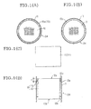
- Figs. 1A through 2D illustrate examples of the canning structure according to the present invention.
- Figs. 1A and 2A are plan views
- Figs. 1B and 2B are rear views
- Figs. 1C and 2C are front views
- Figs. 1D and 2D are cross-sectional views.
- the canning structure according to the present invention comprises a ceramic honeycomb structure 10 before carrying a catalyst, fixed beforehand within a metal case 11 by a holding material 13, having an impermeable layer 70 on an edge plane 13a in the longitudinal direction of the holding material.
- the length t of the impermeable layer 70 for the canning structure 24 according to the present invention should be a minimal length, preferably 10 mm or less, more preferably 7 mm or less, and even more preferably 5 mm or less.
- the plane pressure of the impermeable layer as to the ceramic honeycomb structure should be low, and accordingly, the impermeable layer 70 preferably has plane pressure properties which are approximately the same as those of the holding material 13, or less.
- the edge plane 15a of the holding material at the side of the impermeable layer is preferably on approximately the same plane as the edge plane 10a of the ceramic honeycomb structure.
- the canning structure 24 can be caused to carry the catalyst in a sure manner, thereby allowing the catalyst carrying process to be optimized.
- the impermeable layer 70 is more preferably provided to both longitudinal ends 13a and 13b of the holding material 13, as shown in Figs. 2A through 2D.
- the canning structure according to the present invention is capable of suppressing the catalyst slurry containing the catalyst component from flowing to the holding material in the catalyst carrying process.
- the impermeable layer preferably comprises at least one edge plane in the longitudinal direction of the holding material to which an impermeable material has adhered, so as to facilitate ease of forming an impermeable layer.
- the form of the impermeable material used with the present invention is preferably that of a thin film, or of a rope with a circular, quadrangular, or arbitrary cross-section.
- the impermeable material used with the present invention is not particularly restricted so long as it has excellent impermeability and adhesion, and is preferably formed of resin such as plastic, rubber, paper, cloth, or like fiber.
- the impermeable layer preferably comprises at least one edge plane in the longitudinal direction of the holding material impregnated with impermeable matter such as oils and fats (e.g., grease).
- the impermeable layer and the holding material can be wound onto the perimeter surface of the ceramic honeycomb structure at the same time, so the canning process can be simplified.
- the impermeable layer used with the present invention is preferably combustible.
- the canning structure according to the present invention is capable of protecting the ceramic honeycomb structure from external shock and vibrations, and accordingly chipping and cracking of ceramic honeycomb structures (particularly of those with thin walls (thickness of partitions; 0.10 mm or thinner)) can be prevented at the time of transporting, the catalyst carrying process, the canning process, and handling in each of the processes.
- the canning structure according to the present invention is preferably of an arrangement wherein the metal case has a stuffing structure or a tourniquet structure.
- the metal case has a tourniquet structure
- canning can be performed at a constant plane pressure regardless of irregularities in the diameter of the ceramic honeycomb structure, which is particularly preferable for ceramic honeycomb structures with low mechanical strengths (particularly, those with thin walls).
- the holding material used with the present invention is preferably a non-intumescent ceramic fiber mat.
- the non-intumescent ceramic fiber mat used with the present invention is made up of at least one selected from the following group; alumina, mullite, silicon carbide, silicon nitride, and zirconia.
- This non-intumescent ceramic fiber mat is formed of ceramic fibers wherein the fiber diameter is 2 ⁇ m or greater by less than 6 ⁇ m, such that application of an initial plane pressure of 2 kgf/cm 2 at room temperature and then raising the temperature to 1,000°C results in generation of a plane pressure of at least 1 kgf/cm 2 , and also has the compression properties in that there is little increase or decrease within the actual usage temperature range of the catalytic converter.
- the partition thickness of the ceramic honeycomb structure used with the present invention is preferably 0.10 mm or thinner (more preferably, 0.08 mm or thinner).
- the carrier manufacturer provides uses a ceramic carrier 10 (ceramic honeycomb structure) which has passed inspection, and forms a canning structure 24, which is then packaged and sent to a catalyst manufacturer.
- a ceramic carrier 10 ceramic honeycomb structure
- a holding material 15 having an impermeable layer is wrapped onto the ceramic carrier 10 (ceramic honeycomb structure), which is compressed and fixed within a metal case 11 (i.e., canned), thereby forming the canning structure 24 (See Figs. 1A through 2D).
- the canning structure 24 can be manufactured by wrapping a holding material 13 onto the ceramic carrier 10 (ceramic honeycomb structure), which is compressed and fixed within a metal case 11 (i.e., canned), following which an impermeable material is caused to adhere to at least one edge plane in the longitudinal direction of the holding material, so as to form an impermeable layer 70 (See Figs. 1A through 2D).
- a holding material 13 onto the ceramic carrier 10 (ceramic honeycomb structure), which is compressed and fixed within a metal case 11 (i.e., canned), following which an impermeable material is caused to adhere to at least one edge plane in the longitudinal direction of the holding material, so as to form an impermeable layer 70 (See Figs. 1A through 2D).
- the catalyst manufacturer unpacks this, performs the processes such as causing the canning structure 24 to carry the catalyst (i.e., catalyst coating), thermal processing, inspection, etc., thereby forming a canning catalyst carrier 30, which is then packaged and sent to a canning manufacturer.
- the catalyst i.e., catalyst coating
- thermal processing inspection, etc.
- the catalyst carrying process is performed by pouring a catalyst slurry in from the upper part of the canning structure 24 while suctioning the catalyst slurry out from the lower part of the canning structure 24, thereby causing the ceramic honeycomb structure to be dipped in catalyst slurry such that the canning structure 24 carries the catalyst.
- the holding material provided with the impermeable layer can prevent the catalyst slurry from flowing out to the holding material. Also, the impermeable layer can be easily removed in the thermal process, if combustible.
- the canning manufacturer unpacks this and welds joining parts such as a cone portion 17 and flange 18 and the like to the canning catalyst carrier 30 as necessary, thereby completing the catalytic converter (ceramic honeycomb catalytic converter 1).
- this method for manufacturing ceramic honeycomb catalytic converters is capable of protecting the ceramic honeycomb structure from external shock and vibrations as compared with conventional manufacturing methods (see Fig. 4), and accordingly chipping and cracking of ceramic honeycomb structures can be markedly prevented at the time of transporting, the catalyst carrying process, the canning process, and handling in each of the processes.
- a ceramic carrier (ceramic honeycomb structure) manufactured of cordierite, with a diameter of 106 mm, length of 114 mm, partition thickness of 0.03 mm, and 465 cells/cm 2 , was prepared.
- a non-intumescent ceramic fiber mat (“MAFTEC” (product name), manufactured by MITSUBISHI CHEMICAL CORPORATION) of 1,200 g per 1 m 2 was further wrapped thereupon, as a holding material.
- a rope-shaped impermeable member material: polyethylene
- material polyethylene
- a canning structure was fabricated under the same conditions as the above embodiment, using holding material without the impermeable layer 70, and twenty of such were placed in the ceramic honeycomb catalytic converter manufacturing process shown in Fig. 3.
- Ceramic honeycomb structures manufactured of cordierite, with a diameter of 106 mm, length of 114 mm, partition thickness of 0.06 mm, and 140 cells/cm 2 , were prepared, and were placed in the ceramic honeycomb catalytic converter (pressing canning) manufacturing process shown in Fig. 4.
- the embodiment has impermeable layers on both edges in the longitudinal direction of the holding material, and thus the catalyst slurry can be prevented from flowing out to the ceramic fiber mat at the time of carrying the catalyst.
- the embodiment is capable of protecting the ceramic honeycomb structure from external shock and vibrations, and accordingly chipping and cracking of ceramic honeycomb structures at the time of transporting, the catalyst carrying process, the canning process, and handling in each of the processes, can be markedly reduced.
- the catalyst slurry is prevented from flowing out to the holding material, and chipping and cracking of ceramic honeycomb structures can be prevented at the time of transporting, the catalyst carrying process, the canning process, and handling in each of the processes.
Applications Claiming Priority (2)
| Application Number | Priority Date | Filing Date | Title |
|---|---|---|---|
| JP20726599 | 1999-07-22 | ||
| JP20726599A JP3359596B2 (ja) | 1999-07-22 | 1999-07-22 | キャニング構造体およびその作製方法 |
Publications (2)
| Publication Number | Publication Date |
|---|---|
| EP1070835A1 true EP1070835A1 (fr) | 2001-01-24 |
| EP1070835B1 EP1070835B1 (fr) | 2003-01-22 |
Family
ID=16536940
Family Applications (1)
| Application Number | Title | Priority Date | Filing Date |
|---|---|---|---|
| EP00306239A Expired - Lifetime EP1070835B1 (fr) | 1999-07-22 | 2000-07-21 | Structure enveloppante pour catalyseur et procédé d'élaboration de celle-ci |
Country Status (5)
| Country | Link |
|---|---|
| US (1) | US7163662B1 (fr) |
| EP (1) | EP1070835B1 (fr) |
| JP (1) | JP3359596B2 (fr) |
| CA (1) | CA2314127C (fr) |
| DE (1) | DE60001251T2 (fr) |
Families Citing this family (1)
| Publication number | Priority date | Publication date | Assignee | Title |
|---|---|---|---|---|
| US20100288704A1 (en) * | 2009-05-12 | 2010-11-18 | Jeffrey Michael Amsden | Flow-Through Substrate Assemblies and Methods for Making and Using Said Assemblies |
Citations (5)
| Publication number | Priority date | Publication date | Assignee | Title |
|---|---|---|---|---|
| US4142864A (en) * | 1977-05-31 | 1979-03-06 | Engelhard Minerals & Chemicals Corporation | Catalytic apparatus |
| EP0363681A2 (fr) * | 1988-10-12 | 1990-04-18 | ROTH-TECHNIK GMBH & Co. Forschung für Automobil- und Umwelttechnik | Catalyseur |
| EP0639700A1 (fr) * | 1993-08-20 | 1995-02-22 | Minnesota Mining And Manufacturing Company | Convertisseur catalytique et filtre à particules diesel |
| EP0643204A2 (fr) * | 1993-09-03 | 1995-03-15 | Ngk Insulators, Ltd. | Convertisseur catalytique céramique en nid d'abeille |
| DE19509029A1 (de) * | 1994-06-06 | 1995-12-07 | Ford Werke Ag | Katalytische Behandlungsvorrichtung für Abgase von Kraftfahrzeugen und Verfahren zu ihrer Herstellung |
Family Cites Families (10)
| Publication number | Priority date | Publication date | Assignee | Title |
|---|---|---|---|---|
| US3959865A (en) * | 1972-12-08 | 1976-06-01 | Minnesota Mining And Manufacturing Company | Method of containing a resiliently supported rigid ceramic catalyst support |
| JP2578176B2 (ja) * | 1988-08-12 | 1997-02-05 | 日本碍子株式会社 | 多孔質セラミックハニカムフィルターおよびその製法 |
| US5114581A (en) * | 1991-01-10 | 1992-05-19 | Ceramem Corporation | Back-flushable filtration device and method of forming and using same |
| JP2798871B2 (ja) | 1993-09-03 | 1998-09-17 | 日本碍子株式会社 | セラミックハニカム触媒コンバータ |
| JP3246215B2 (ja) | 1994-08-25 | 2002-01-15 | 三菱化学株式会社 | 排気ガス浄化装置の製造方法 |
| JP3294036B2 (ja) * | 1995-01-26 | 2002-06-17 | 日本碍子株式会社 | ハニカム触媒コンバータ |
| JP3536060B2 (ja) * | 1995-07-06 | 2004-06-07 | 東京窯業株式会社 | セラミックハニカム構造体端面の目封じ方法 |
| JPH09112248A (ja) * | 1995-10-16 | 1997-04-28 | Hino Motors Ltd | ディーゼルパティキュレートフィルタの逆洗再生装置 |
| US6405437B1 (en) * | 1997-09-17 | 2002-06-18 | Arvinmeritor, Inc. | Apparatus and method for encasing an object in a case |
| US6017498A (en) * | 1998-01-14 | 2000-01-25 | Metex Mfg. Corporation | Catalytic converter support device |
-
1999
- 1999-07-22 JP JP20726599A patent/JP3359596B2/ja not_active Expired - Lifetime
-
2000
- 2000-07-18 CA CA002314127A patent/CA2314127C/fr not_active Expired - Fee Related
- 2000-07-18 US US09/618,797 patent/US7163662B1/en not_active Expired - Lifetime
- 2000-07-21 DE DE60001251T patent/DE60001251T2/de not_active Expired - Lifetime
- 2000-07-21 EP EP00306239A patent/EP1070835B1/fr not_active Expired - Lifetime
Patent Citations (5)
| Publication number | Priority date | Publication date | Assignee | Title |
|---|---|---|---|---|
| US4142864A (en) * | 1977-05-31 | 1979-03-06 | Engelhard Minerals & Chemicals Corporation | Catalytic apparatus |
| EP0363681A2 (fr) * | 1988-10-12 | 1990-04-18 | ROTH-TECHNIK GMBH & Co. Forschung für Automobil- und Umwelttechnik | Catalyseur |
| EP0639700A1 (fr) * | 1993-08-20 | 1995-02-22 | Minnesota Mining And Manufacturing Company | Convertisseur catalytique et filtre à particules diesel |
| EP0643204A2 (fr) * | 1993-09-03 | 1995-03-15 | Ngk Insulators, Ltd. | Convertisseur catalytique céramique en nid d'abeille |
| DE19509029A1 (de) * | 1994-06-06 | 1995-12-07 | Ford Werke Ag | Katalytische Behandlungsvorrichtung für Abgase von Kraftfahrzeugen und Verfahren zu ihrer Herstellung |
Also Published As
| Publication number | Publication date |
|---|---|
| EP1070835B1 (fr) | 2003-01-22 |
| CA2314127C (fr) | 2004-09-28 |
| CA2314127A1 (fr) | 2001-01-22 |
| JP3359596B2 (ja) | 2002-12-24 |
| DE60001251T2 (de) | 2003-11-13 |
| US7163662B1 (en) | 2007-01-16 |
| DE60001251D1 (de) | 2003-02-27 |
| JP2001032709A (ja) | 2001-02-06 |
Similar Documents
| Publication | Publication Date | Title |
|---|---|---|
| EP2507490B1 (fr) | Nappe de montage | |
| KR101145019B1 (ko) | 오염 조절 요소의 유지재 및 오염 조절 장치 | |
| KR101299836B1 (ko) | 오염 제어 요소 장착 시스템 및 오염 제어 장치 | |
| US20010036427A1 (en) | Cell structure mounting container and assembly thereof | |
| JP2001526115A (ja) | 触媒コンバータの製造方法 | |
| JP2012501406A (ja) | フレキシブル縁保護剤を備えた装着マットおよび該装着マットが組込まれた排気ガス処理装置 | |
| EP0947673B1 (fr) | Procedé d'assemblage d'un convertisseur catalytique de structure en nid d'abeille et pièce de support pour cette structure | |
| JP3246215B2 (ja) | 排気ガス浄化装置の製造方法 | |
| US7163662B1 (en) | Canning structure and manufacturing method thereof | |
| JP3553424B2 (ja) | セラミックハニカム構造体、セラミックハニカム触媒担体及びこれらを用いたセラミックハニカム触媒コンバータ | |
| CA2313586C (fr) | Structure de mise en boite et methode de transport d'un catalyseur a l'aide d'une telle structure | |
| EP2811131B1 (fr) | Matériau d'étanchéité de maintien, procédé de fabrication d'un tel matériau, appareil de purification de gaz d'échappement et procédé de fabrication dudit appareil | |
| EP1101911B1 (fr) | Procede de fabrication d'un convertisseur catalytique au moyen d'un corps structural avec enveloppe metallique | |
| KR100547206B1 (ko) | 배기가스 정화용 촉매의 제조방법 | |
| Gulati | New developments in catalytic converter durability | |
| JPH10141052A (ja) | セラミック触媒コンバータの製造方法及びセラミック触媒コンバータ | |
| US20070178024A1 (en) | Exhaust Line And Power Train Comprising Same | |
| JPH09155204A (ja) | ハニカム体外周に弾性保持部材を有するメタル担体 | |
| JP2001248432A (ja) | 排気ガス浄化用触媒コンバータ |
Legal Events
| Date | Code | Title | Description |
|---|---|---|---|
| PUAI | Public reference made under article 153(3) epc to a published international application that has entered the european phase |
Free format text: ORIGINAL CODE: 0009012 |
|
| AK | Designated contracting states |
Kind code of ref document: A1 Designated state(s): DE FR GB |
|
| AX | Request for extension of the european patent |
Free format text: AL;LT;LV;MK;RO;SI |
|
| 17P | Request for examination filed |
Effective date: 20010430 |
|
| AKX | Designation fees paid |
Free format text: DE FR GB |
|
| 17Q | First examination report despatched |
Effective date: 20010913 |
|
| GRAG | Despatch of communication of intention to grant |
Free format text: ORIGINAL CODE: EPIDOS AGRA |
|
| GRAG | Despatch of communication of intention to grant |
Free format text: ORIGINAL CODE: EPIDOS AGRA |
|
| GRAH | Despatch of communication of intention to grant a patent |
Free format text: ORIGINAL CODE: EPIDOS IGRA |
|
| GRAH | Despatch of communication of intention to grant a patent |
Free format text: ORIGINAL CODE: EPIDOS IGRA |
|
| GRAA | (expected) grant |
Free format text: ORIGINAL CODE: 0009210 |
|
| AK | Designated contracting states |
Kind code of ref document: B1 Designated state(s): DE FR GB |
|
| REG | Reference to a national code |
Ref country code: GB Ref legal event code: FG4D |
|
| REF | Corresponds to: |
Ref document number: 60001251 Country of ref document: DE Date of ref document: 20030227 Kind code of ref document: P |
|
| ET | Fr: translation filed | ||
| PLBE | No opposition filed within time limit |
Free format text: ORIGINAL CODE: 0009261 |
|
| STAA | Information on the status of an ep patent application or granted ep patent |
Free format text: STATUS: NO OPPOSITION FILED WITHIN TIME LIMIT |
|
| 26N | No opposition filed |
Effective date: 20031023 |
|
| PGFP | Annual fee paid to national office [announced via postgrant information from national office to epo] |
Ref country code: GB Payment date: 20040709 Year of fee payment: 5 |
|
| PG25 | Lapsed in a contracting state [announced via postgrant information from national office to epo] |
Ref country code: GB Free format text: LAPSE BECAUSE OF NON-PAYMENT OF DUE FEES Effective date: 20050721 |
|
| GBPC | Gb: european patent ceased through non-payment of renewal fee |
Effective date: 20050721 |
|
| REG | Reference to a national code |
Ref country code: FR Ref legal event code: PLFP Year of fee payment: 17 |
|
| REG | Reference to a national code |
Ref country code: FR Ref legal event code: PLFP Year of fee payment: 18 |
|
| REG | Reference to a national code |
Ref country code: FR Ref legal event code: PLFP Year of fee payment: 19 |
|
| PGFP | Annual fee paid to national office [announced via postgrant information from national office to epo] |
Ref country code: FR Payment date: 20190619 Year of fee payment: 20 |
|
| PGFP | Annual fee paid to national office [announced via postgrant information from national office to epo] |
Ref country code: DE Payment date: 20190710 Year of fee payment: 20 |
|
| REG | Reference to a national code |
Ref country code: DE Ref legal event code: R071 Ref document number: 60001251 Country of ref document: DE |