EP1070772A2 - Electroplating device, and process for electroplating work using the device - Google Patents
Electroplating device, and process for electroplating work using the device Download PDFInfo
- Publication number
- EP1070772A2 EP1070772A2 EP00113496A EP00113496A EP1070772A2 EP 1070772 A2 EP1070772 A2 EP 1070772A2 EP 00113496 A EP00113496 A EP 00113496A EP 00113496 A EP00113496 A EP 00113496A EP 1070772 A2 EP1070772 A2 EP 1070772A2
- Authority
- EP
- European Patent Office
- Prior art keywords
- work
- magnet
- electroplating
- plated film
- anode
- Prior art date
- Legal status (The legal status is an assumption and is not a legal conclusion. Google has not performed a legal analysis and makes no representation as to the accuracy of the status listed.)
- Granted
Links
- 238000009713 electroplating Methods 0.000 title claims abstract description 72
- 238000000034 method Methods 0.000 title claims description 16
- 230000008569 process Effects 0.000 title claims description 16
- 238000007747 plating Methods 0.000 claims abstract description 69
- 229910052751 metal Inorganic materials 0.000 claims description 30
- 239000002184 metal Substances 0.000 claims description 30
- 230000015572 biosynthetic process Effects 0.000 description 8
- 239000000463 material Substances 0.000 description 7
- 239000000843 powder Substances 0.000 description 7
- 125000006850 spacer group Chemical group 0.000 description 6
- 230000000052 comparative effect Effects 0.000 description 5
- 239000011810 insulating material Substances 0.000 description 5
- 238000005259 measurement Methods 0.000 description 5
- 239000000203 mixture Substances 0.000 description 5
- 229910001111 Fine metal Inorganic materials 0.000 description 4
- BGPVFRJUHWVFKM-UHFFFAOYSA-N N1=C2C=CC=CC2=[N+]([O-])C1(CC1)CCC21N=C1C=CC=CC1=[N+]2[O-] Chemical compound N1=C2C=CC=CC2=[N+]([O-])C1(CC1)CCC21N=C1C=CC=CC1=[N+]2[O-] BGPVFRJUHWVFKM-UHFFFAOYSA-N 0.000 description 4
- 230000007246 mechanism Effects 0.000 description 4
- 229910052761 rare earth metal Inorganic materials 0.000 description 4
- 150000002910 rare earth metals Chemical class 0.000 description 4
- UFHFLCQGNIYNRP-UHFFFAOYSA-N Hydrogen Chemical compound [H][H] UFHFLCQGNIYNRP-UHFFFAOYSA-N 0.000 description 3
- 229910021586 Nickel(II) chloride Inorganic materials 0.000 description 3
- KGBXLFKZBHKPEV-UHFFFAOYSA-N boric acid Chemical compound OB(O)O KGBXLFKZBHKPEV-UHFFFAOYSA-N 0.000 description 3
- 239000004327 boric acid Substances 0.000 description 3
- 230000007797 corrosion Effects 0.000 description 3
- 238000005260 corrosion Methods 0.000 description 3
- 230000000694 effects Effects 0.000 description 3
- 230000004907 flux Effects 0.000 description 3
- 238000007654 immersion Methods 0.000 description 3
- 229910021645 metal ion Inorganic materials 0.000 description 3
- QMMRZOWCJAIUJA-UHFFFAOYSA-L nickel dichloride Chemical compound Cl[Ni]Cl QMMRZOWCJAIUJA-UHFFFAOYSA-L 0.000 description 3
- LGQLOGILCSXPEA-UHFFFAOYSA-L nickel sulfate Chemical compound [Ni+2].[O-]S([O-])(=O)=O LGQLOGILCSXPEA-UHFFFAOYSA-L 0.000 description 3
- 229910000008 nickel(II) carbonate Inorganic materials 0.000 description 3
- 229910000363 nickel(II) sulfate Inorganic materials 0.000 description 3
- ZULUUIKRFGGGTL-UHFFFAOYSA-L nickel(ii) carbonate Chemical compound [Ni+2].[O-]C([O-])=O ZULUUIKRFGGGTL-UHFFFAOYSA-L 0.000 description 3
- 229910045601 alloy Inorganic materials 0.000 description 2
- 239000000956 alloy Substances 0.000 description 2
- 230000008901 benefit Effects 0.000 description 2
- 238000000748 compression moulding Methods 0.000 description 2
- 230000003247 decreasing effect Effects 0.000 description 2
- 238000010586 diagram Methods 0.000 description 2
- 230000002708 enhancing effect Effects 0.000 description 2
- 239000003822 epoxy resin Substances 0.000 description 2
- 239000007769 metal material Substances 0.000 description 2
- 239000002245 particle Substances 0.000 description 2
- 229920000647 polyepoxide Polymers 0.000 description 2
- 238000007712 rapid solidification Methods 0.000 description 2
- 230000009467 reduction Effects 0.000 description 2
- 230000001105 regulatory effect Effects 0.000 description 2
- 239000002253 acid Substances 0.000 description 1
- 239000003513 alkali Substances 0.000 description 1
- 239000011230 binding agent Substances 0.000 description 1
- 230000001276 controlling effect Effects 0.000 description 1
- 238000005520 cutting process Methods 0.000 description 1
- 230000002939 deleterious effect Effects 0.000 description 1
- 230000006866 deterioration Effects 0.000 description 1
- JEIPFZHSYJVQDO-UHFFFAOYSA-N iron(III) oxide Inorganic materials O=[Fe]O[Fe]=O JEIPFZHSYJVQDO-UHFFFAOYSA-N 0.000 description 1
- 239000006247 magnetic powder Substances 0.000 description 1
- 238000004519 manufacturing process Methods 0.000 description 1
- 229910001172 neodymium magnet Inorganic materials 0.000 description 1
- 230000003647 oxidation Effects 0.000 description 1
- 238000007254 oxidation reaction Methods 0.000 description 1
- 230000003014 reinforcing effect Effects 0.000 description 1
- 229920005989 resin Polymers 0.000 description 1
- 239000011347 resin Substances 0.000 description 1
- 239000013589 supplement Substances 0.000 description 1
- 238000004381 surface treatment Methods 0.000 description 1
Images




Classifications
-
- C—CHEMISTRY; METALLURGY
- C25—ELECTROLYTIC OR ELECTROPHORETIC PROCESSES; APPARATUS THEREFOR
- C25D—PROCESSES FOR THE ELECTROLYTIC OR ELECTROPHORETIC PRODUCTION OF COATINGS; ELECTROFORMING; APPARATUS THEREFOR
- C25D3/00—Electroplating: Baths therefor
-
- H—ELECTRICITY
- H01—ELECTRIC ELEMENTS
- H01F—MAGNETS; INDUCTANCES; TRANSFORMERS; SELECTION OF MATERIALS FOR THEIR MAGNETIC PROPERTIES
- H01F41/00—Apparatus or processes specially adapted for manufacturing or assembling magnets, inductances or transformers; Apparatus or processes specially adapted for manufacturing materials characterised by their magnetic properties
- H01F41/02—Apparatus or processes specially adapted for manufacturing or assembling magnets, inductances or transformers; Apparatus or processes specially adapted for manufacturing materials characterised by their magnetic properties for manufacturing cores, coils, or magnets
- H01F41/0253—Apparatus or processes specially adapted for manufacturing or assembling magnets, inductances or transformers; Apparatus or processes specially adapted for manufacturing materials characterised by their magnetic properties for manufacturing cores, coils, or magnets for manufacturing permanent magnets
- H01F41/026—Apparatus or processes specially adapted for manufacturing or assembling magnets, inductances or transformers; Apparatus or processes specially adapted for manufacturing materials characterised by their magnetic properties for manufacturing cores, coils, or magnets for manufacturing permanent magnets protecting methods against environmental influences, e.g. oxygen, by surface treatment
-
- C—CHEMISTRY; METALLURGY
- C25—ELECTROLYTIC OR ELECTROPHORETIC PROCESSES; APPARATUS THEREFOR
- C25D—PROCESSES FOR THE ELECTROLYTIC OR ELECTROPHORETIC PRODUCTION OF COATINGS; ELECTROFORMING; APPARATUS THEREFOR
- C25D17/00—Constructional parts, or assemblies thereof, of cells for electrolytic coating
- C25D17/10—Electrodes, e.g. composition, counter electrode
- C25D17/12—Shape or form
-
- C—CHEMISTRY; METALLURGY
- C25—ELECTROLYTIC OR ELECTROPHORETIC PROCESSES; APPARATUS THEREFOR
- C25D—PROCESSES FOR THE ELECTROLYTIC OR ELECTROPHORETIC PRODUCTION OF COATINGS; ELECTROFORMING; APPARATUS THEREFOR
- C25D7/00—Electroplating characterised by the article coated
- C25D7/04—Tubes; Rings; Hollow bodies
-
- Y—GENERAL TAGGING OF NEW TECHNOLOGICAL DEVELOPMENTS; GENERAL TAGGING OF CROSS-SECTIONAL TECHNOLOGIES SPANNING OVER SEVERAL SECTIONS OF THE IPC; TECHNICAL SUBJECTS COVERED BY FORMER USPC CROSS-REFERENCE ART COLLECTIONS [XRACs] AND DIGESTS
- Y10—TECHNICAL SUBJECTS COVERED BY FORMER USPC
- Y10T—TECHNICAL SUBJECTS COVERED BY FORMER US CLASSIFICATION
- Y10T29/00—Metal working
- Y10T29/49—Method of mechanical manufacture
- Y10T29/49002—Electrical device making
- Y10T29/4902—Electromagnet, transformer or inductor
- Y10T29/49075—Electromagnet, transformer or inductor including permanent magnet or core
Definitions
- the present invention relates to an electroplating device useful for electroplating a work having a hole communicating with the outside, particularly, a ring-shaped work such as a ring-shaped bonded magnet, and a process for electroplating such a work using the device.
- a rare earth metal-based permanent magnet such as an R-Fe-B based permanent magnet, of which an Nd-Fe-B based permanent magnet is representative, is used at present in a variety of fields, because it is produced from an inexpensive material rich in natural resources and has a high magnetic characteristic.
- a bonded magnet which is easy to form into a certain shape from a material containing a magnetic powder and a resin binder as main components.
- a ring-shaped bonded magnet is utilized, particularly, In various small-sized motors such as a spindle motor, or in a servomotor used in an actuator.
- the rare earth metal-based permanent magnet contains a rare earth metal (R) which is liable to be corroded by oxidation in the atmosphere. Therefore, when the magnet is used without being subjected to any surface treatment, the corrosion of the magnet is advanced from the surface due to the presence of a small amount of an acid, an alkali or moisture to produce a rust, and as a result, the deterioration and variability of the magnetic characteristic of the magnet occur. Therefore, a plated film has been conventionally formed as a corrosion-resistant film on a surface of a magnet by subjecting the magnet to an electroplating, but a higher accuracy is required in the formation of the plated film, attendant on the recent demands for the reduction in size of the magnet and for the complication of the shape.
- R rare earth metal
- the high dimensional accuracy is required for both of the outer and inner surfaces of the magnet and hence, a uniform plated film must be formed on the outer surface, but also a uniform plated film must be formed particularly on the inner surface.
- L represents a length of the magnet in a direction of a center axis
- D represents an inside diameter of the magnet
- an anode is inserted into and disposed in such portion (for example, see Japanese Patent Application Laid-open No.3-6399).
- the distance between the inner surface of the magnet and the anode cannot be averagely regularized. Therefore, an obtained effect is only that a plated film can be formed efficiently on the inner surface, and the variability of formation of the plated film from portion to portion of the inner surface cannot be overcome.
- an electroplating device comprising an anode which is inserted through and disposed in a hole provided in a work and communicating with the outside, and a member for rotating the work about its center axis and supplying a plating electric current to the work.
- an electroplating device comprising an anode which is inserted through and disposed in a hole provided in a work and communicating with the outside, a member for rotating the work about its center axis, and a member for supplying a plating electric current to the work.
- an electroplating device comprising an anode which is inserted through and disposed in a hole provided in a work and communicating with the outside, a driving roller made of a metal and adapted to abut against the outer surface of the work to support the work for rotating the work about its center axis and supplying a plating electric current to the work, and a follower roller adapted to abut against the outer surface of the work to support the work.
- an electroplating device comprising an anode which is inserted through and disposed in a hole provided in a work and communicating with the outside, a driving roller adapted to abut against the outer surface of the work to support the work for rotating the work about its center axis, and a follower roller made of a metal and adapted to abut against the outer surface of the work to support the work for supplying a plating electric current to the work.
- an electroplating device comprising an anode which is inserted through and disposed in a hole provided in a work and communicating with the outside, and a means for allowing a plating solution within the hole in the work to flow.
- the device in addition to the first or second feature, further includes a means for allowing a plating solution within the hole in the work to flow.
- a process for electroplating a work having a hole communicating with the outside, using an electroplating device according to the first or second feature is provided.
- the work having the hole communicating with the outside is a ring-shaped work.
- the ring-shaped work is a ring-shaped bonded magnet.
- a ring-shaped bonded magnet having a plated film on the entire surface thereof, wherein the thickness of the plated film formed on the outer surface is equal to or smaller than that of the plated film formed on the inner surface, and the variability of thickness of the plated film from portion to portion of the outer and inner surfaces is equal to or smaller than 25 %.
- a uniform plated film can be formed on both of the outer and inner surfaces of a work having a hole communicating with the outside, such as a ring-shaped work, of which a ring-shaped bonded magnet is representative.
- An anode 4 is, for example, in the form of a bar circular in section, and is inserted through and disposed in a hole in a hollow work 1, so that the direction of its center axis is parallel to the direction of a center axis of the work 1, and desirably, so that it is located on the center axis of the work 1.
- a member for rotating the work about its center axis and supplying a plating electric current to the work is, for example, a driving roller 2-a made of a metal.
- the driving roller 2-a is adapted to be rotated by a motor and a belt about its center axis to rotate the work about its center axis, and is also adapted to be connected to a negative pole of a rectifier to supply the plating electric current to the work.
- the driving roller 2-a may be brought into abutment against an outer surface of the work 1, or may be brought into abutment against an inner surface of the work 1.
- Figs.1a to 1d Several examples of arrangements will be shown in Figs.1a to 1d.
- FIG.1a shows the positional relationship among the work 1, the anode 4 and the driving roller 2-a in a view taken from an end face of the work.
- Fig.1a shows an arrangement in which the work 1 is placed onto and supported on the driving roller 2-a and a follower roller 2-b disposed in parallel to the driving roller 2-a, and the driving roller 2-a is rotated as shown in Fig.1a to rotate the work about its center axis, as shown in Fig.1a, and to supply a plating electric current to the work.
- Fig.1b shows an arrangement in which the driving roller 2-a is brought into abutment against the work 1 from the above, thereby clamping the work between the driving roller 2-a and the follower roller 2-b put into abutment against an upper portion of the inner surface of the work, and the driving roller 2-a is rotated, as shown in Fg.1b, thereby rotating the work about its center axis, as shown in Fg.1b, and at the same time, supplying the plating electric current to the work.
- Fig.1c shows an arrangement in which the work 1 is placed onto and supported on the two follower rollers 2-b disposed in parallel to each other, and the driving roller 2-a is brought into abutment against the work from the above and rotated as shown in Fig.1c, thereby rotating the work about its center axis, as shown in Fig.1c, and at the same time, supplying the plating electric current to the work.
- Fig.1d shows an arrangement in which the driving roller 2-a is brought into abutment against the upper portion of the inner surface of the work 1 and rotated as shown in Fig.1d, thereby rotating the work about its center axis, as shown in Fig.1d, and at the same time, supplying the plating electric current to the work.
- the plating electric current can be supplied to the work by the driving roller 2-a made of the metal to form a plated film on the work 1.
- the work is rotated about its center axis, desirably, about the center axis of the anode by a driving force of the driving roller. Therefore, the distance between the inner surface of the work and the anode inserted through and disposed in the hole in the hollow work can be averagely regularized to overcome the variability of formation of the plated film from portion to portion of the inner surface.
- the distance between the outer surface of the work and the positive electrode plate can be also averagely regularized to overcome the variability of formation of the plated film from portion to portion of the outer surface.
- This device has a feature that a member for rotating a work about its center axis and a member for supplying a plating electric current to the work are different members, unlike the device according to the first embodiment.
- the member for rotating the work 1 about its center axis is, for example, a driving roller 2-a.
- the member for supplying a plating electric current to the work 1 is, for example, a follower roller 2-b made of a metal.
- FIG.2a shows the positional relationship among the work 1, the anode 4, the driving roller 2-a and the follower roller 2-b in a view taken from an end face of the work.
- Fig.2a shows an arrangement in which the work 1 is placed onto and supported on the driving roller 2-a and the follower roller 2-b of the metal disposed in parallel to the driving roller 2-a, and is rotated about its center axis, as shown in Fig.2a, by rotating the driving roller 2-a as shown in Fig.2a, and a plating electric current is supplied to the work by the follower roller 2-b.
- Fig.2b shows an arrangement in which the driving roller 2-a and the follower roller 2-b are brought into abutment against an upper portion of an inner surface of the work 1, whereby the driving roller 2-a is rotated, as shown in Fg.2b, thereby rotating the work about its center axis, as shown in Fg.2b, and at the same time, the plating electric current is supplied to the work by the follower roller made of the metal.
- Fig.2c shows an arrangement in which the driving roller 2-a is brought into abutment against the upper portion of the inner surface of the work 1, thereby clamping the work between the driving roller 2-a and the follower roller 2-b of the metal put into abutment against the work from the above, and the work is rotated about its center axis, as shown in Fig.2c by rotating the driving roller 2-a, as shown in Fig.2c, and at the same time, the plating electric current is supplied to the work by the follower roller of the metal.
- Fig.2d shows an arrangement in which the driving roller 2-a is brought into abutment against the work 1 from the above, thereby clamping the work between the driving roller 2-a and the follower roller 2-b of the metal put into abutment against the upper portion of the inner surface of the work, and the work is rotated about its center axis, as shown in Fig.2d by rotating the driving roller 2-a, as shown in Fig.2d, and at the same time, the plating electric current is supplied to the work by the follower roller of the metal.
- An electroplating device corresponds to one of the arrangements of the device according to the first embodiment, which is shown in Fig.1a.
- An electroplating device corresponds to one of the arrangements of the device according to the second embodiment, which is shown in Fig.2a.
- air bubbles produced upon the immersion of a work into a plating bath and hydrogen gas produced during the electroplating can be prevented from being resident on an inner upper portion of a work by a means for allowing a plating solution within a hole in the work to flow.
- components such as metal ion and a brightener in the plating solution are supplied neither too much nor too less even into the hole in the work and hence, it is possible to form a uniform plated film on the inner surface of the work.
- An electroplating device is similar to the electroplating device according to any of the first and second embodiments, except that it further includes a means for allowing a plating solution within the hole in the work to flow.
- it is possible to form a further uniform plated film on the inner surface of the work.
- a uniform plated film can be formed not only on an outer surface but also on an inner surface of a hollow work which has a hole communicating with the outside and which is represented by a ring-shaped bonded magnet.
- a ring-shaped bonded magnet is provided, which is suitably utilized to a spindle motor or the like.
- the hole provided in the hollow work and communicating with the outside may be made through opposite ends of the work, or may be closed at one of the opposite ends.
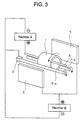
- Fig.3 is a schematic diagram of an apparatus used in an embodiment of a process for electroplating a ring-shaped bonded magnet using the electroplating device.
- the electroplating device includes an anode inserted through and disposed in a hole provided in a work and communicating with the outside, a driving roller made of a metal and adapted to abut against an outer surface of the work to support the work for rotating the work about its center axis and supplying a plating electric current to the work, and a follower roller which is adapted to abut against an outer surface of the work to support the work.
- a plating solution and a plating bath are not shown in Fig.3.
- the work designated by reference character 1 and having the hole communicating with the outside is a ring-shaped bonded magnet.
- the magnet is placed onto and supported on the driving roller 2-a made of the metal and the follower roller 2-b which are disposed in parallel to each other.
- the driving roller 2-a made of the metal is clamped by a member 3 of a metal having a spring property and connected to negative poles of rectifiers A and B, thereby reliably supplying a plating electric current to the magnet.
- the follower roller 2-b is formed of an insulating material.
- the anode designated by reference character 4 is in the form of bar circular in section and is disposed through the hole in the magnet, so that the direction of its center axis is parallel to the direction of a center axis of the magnet, desirably, so that it is located on the center axis of the magnet.
- the anode 4 is connected to a positive pole of a rectifier A.
- a positive electrode plate denoted by reference character 5 is connected to a positive pole of a rectifier B.
- the plated films can be formed on the outer and inner surfaces of the magnet, so that the thickness thereof can be controlled by conducting the supplying of the plating electric currents to the anode 4 and the positive electrode plate 5 using the different rectifiers and by rectifying the currents supplied to the anode and the positive electrode plate.
- the plated films can be formed on the outer and inner surfaces of the magnet, so that the thickness of the plated film on the outer surface is larger than or equal to that of the plated film on the inner surface, while maintaining uniformity of the thickness of the plated film.
- the thickness of the plated film on the outer surface of the magnet can be smaller than that of the plated film on the inner surface of the magnet.
- a yoke usually used in the motor of this type for preventing the leakage of a magnetic flux may be disposed outside or inside the magnet depending upon the structure of the spindle motor. If the thickness of a plated film formed on the surface of the magnet on the side of the yoke disposed is larger than that of a plated film formed on the other side, the plated film formed on the side of the yoke functions not only as a mere corrosion-resistant film, but also serves to prevent the leakage of the magnetic flux. Therefore, a rotor having no yoke provided thereon can be produced.
- the distance between the magnet and a stator can be adjusted to a small value by controlling the thickness of the plated film on the inner surface of the magnet and hence, the characteristic of the motor can be enhanced. Further, if the thickness of the plated film on the outer surface of the magnet is substantially equal to that of the plated film on the inner surface of the magnet, the strength of the ring-shaped bonded magnet is enhanced remarkably by a mechanically reinforcing effect provided by the plated films.
- the control of the thickness of the plated film on each of the outer and inner surfaces of the magnet can be also achieved, for example, by regulating the distance between the magnet and the positive electrode plate.
- the thickness of the plated film on each of the outer and inner surfaces of the magnet can be controlled easily, for example, even on a mass-production line in which it is difficult to regulate the distance between the magnet and the positive electrode plate.
- the magnet 1 When the driving roller 2-a is rotated about its center axis as shown in Fig.3 by a motor and a belt which are not shown, the magnet 1 is also rotated about its center axis with the rotation of the driving roller 2-a, as shown in Fig.3, whereby the follower roller 2-b is also rotated.
- the distance between the inner surface of the magnet 1 and the anode 4 inserted through and disposed in the hole in the magnet is averagely regularized by the rotation of the magnet and hence, a plated film can be formed with no variability of thickness from portion to portion of the inner surface of the magnet.
- the distance between the outer surface of the magnet 1 and the positive electrode plate 5 is averagely regularized by the rotation of the magnet and hence, a uniform plated film can be also formed on the outer surface of the magnet.
- the follower roller 2-b has been described as being formed of the insulating material in Fig.3, but may be formed of a metal, as is the driving roller 2-a, so that the plating electric current can be supplied to the magnet.
- the follower roller 2-b may be a driving roller. It is desirable that at least the member for supplying the plating electric current to the magnet is rotated, whether it is the driving roller or the follower roller. This is because if such member is not rotated, there is a possibility that the member causes an uneven increase in thickness of the plated film to obstruct the rotation of the magnet, and there is a possibility that the plating electric current cannot be supplied sufficiently to the magnet.
- the metal material forming the anode 4 is particularly not limited, but it is desirable that the material is a metal identical to the metal forming the plated film, because an effect of supplement of plated-film forming metal ions in a plating solution is provided, leading to an enhanced plating efficiency. In this case, however, there is a possibility that the thickness of such anode is gradually decreased with the advance of the plating treatment and as a result, the anode cannot fulfill its function, but also fine metal pieces or a metal powder is produced and dropped onto and accumulated on the inner surface of the magnet.
- the anode is made of a metal material identical to the plated-film forming metal, it is desirable that the anode is placed into a mesh-like net made of an inert metal such as Pt or an insulating material to prevent the dropping of fine metal pieces or a metal powder onto the inner surface of the magnet.
- a cylindrical net cage made of an inert metal may be used as the anode and, metal chips or pieces as a material for forming a plated film may be placed into the net cage, thereby enhancing the plating efficiency.
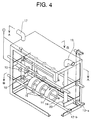
- Fig.4 is a schematic view of an electroplating device capable of electroplating six magnets simultaneously in a state in which three magnets have been set at a lower stage.
- the device is shown as being partially perspective and cutaway to facilitate the understanding of the internal situation of the device.
- a driving roller 12-a is mounted, so that it can be rotated about its center axis through a belt (not shown) by a motor (not shown).
- the driving roller 12-a is made of a metal to be able to supply a plating electric current to the magnets, and is clamped by a member 13 of a metal which has a spring property and which is connected to a negative pole of a rectifier (not shown) to reliably supply the plating electric current to the magnets.
- Reference character 12-b designates a follower roller formed of an insulating material.
- a bar-shaped anode denoted by reference character 14 is detachably connected to a positive pole of the rectifier by a wire which is not shown.
- the adjacent magnets are set so that they are spaced at a distance apart from each other by a spacer 16 made of an insulating material.
- the provision of the spacers 16 ensures that a plated film can be formed satisfactorily even on end faces of each magnet.
- the driving roller 12-a When the driving roller 12-a is rotated about its center axis, as shown in Fig.4, the magnets 11 are also rotated about their center axes with the rotation of the driving roller 12-a, as shown in Fig.4, whereby the follower roller 12-b is also rotated.
- the distance between the inner surface of each of the magnets and the anode 14 inserted through and disposed in the hole in each of the magnets is averagely regularized by the rotation of the magnets and hence, a plated film can be formed with no variability of the thickness from portion to portion of the inner surface of each of the magnets.
- the distance between the outer surface of each of the magnets and the positive electrode plate is averagely regularized by the rotation of the magnets and hence, a uniform plated film can be also formed on the outer surface of each of the magnets.
- the electroplating device may include a mechanism capable of regulating the distance between the two rollers 12-a and 12-b, and a mechanism capable of locating the anode 14 on the center axes of the magnets.
- a weight member 24 may be mounted to abut against a lower portion of an inner surface of the work 11 in order to reliably supply a plating electric current to the work.
- a bar-shaped member 25 having a spacer 26 attached thereto may be inserted through and disposed in the hole in the work in order to quiet the movement of the magnet which is being treated.
- the bar-shaped member 25 is disposed, so that the weight of the work is not applied thereto.
- the bar-shaped member 25 is detachably attached to the device.
- the electroplating device shown in Fig.4 is provided with a member 17 having a discharge port 18 for a plating solution, and a member 19 having an intake port 20 for the plating solution. Both of the members are connected to a plating solution circulating pump (not shown) by a hose (not shown).
- Fig.6 is a sectional view of the electroplating device taken along a line A-A in Fig.4.
- the plating solution is introduced into the member 17 by the plating solution circulating pump, discharged vigorously through the discharge port 18, passed through the holes in the magnets and drawn through the intake port 20 into the member 19.
- the plating solution in the holes in the magnets can be allowed to flow by circulating the plating solution in the above manner. Therefore, air bubbles produced upon the immersion of the magnets into a plating bath and hydrogen gas produced during the electroplating, which may hinder the formation of a plated film on the inner surface of each of the magnets, can be prevented from being resident on the inner upper portion of the magnet. Additionally, components such as metal ions and a brightener in the plating solution can be supplied neither too much nor too less even into the holes in the works.
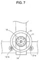
- Fig.7 is an enlarged view of an area near the discharge port 18 for a plating solution in the electroplating device, taken along a line B-B in Fig.4.
- the plating solution can be discharged vigorously by fitting a cap having a large number of fine bores 21 into the discharge port 18.
- An epoxy resin was added in an amount of 2 % by weight to an alloy powder produced in a rapid solidification process and having an average particle size of 150 ⁇ m and a composition comprising 12 % by atom of Nd, 77 % by atom of Fe, 6 % by atom of B and 5 % by atom of Co, and they were kneaded together.
- the resulting material was subjected to a compression molding under a pressure of 686 N/mm 2 and then cured for 1 hour at 170°C, thereby producing fifty magnets.
- the 50 produced magnets and 10 kg of a fine Cu-power producing material comprising short columnar pieces (made by cutting a wire) each having a diameter of 1 mm and a length of 1 mm were thrown into a treating chamber in a vibrated-type barrel finishing machine having a volume of 3.5 liters, where they were subjected to a dry treatment for 3 hours under conditions of a vibration frequency of 70 Hz and a vibration amplitude of 3 mm, thereby producing magnets each having a film layer formed of a fine Cu powder on the entire surface thereof.
- Ten of the 50 magnets were set in the electroplating device including the mechanism shown in Fig.4, so that the anode was located apparently on the center axes of the magnets.
- the adjacent magnets were disposed, so that they were spaced at a distance of 5 mm to 8 mm apart from each other using the spacer.
- the device was disposed within a plating bath, so that the directions of the rollers were parallel to the positive electrode plate.
- the magnets were subjected to an Ni-electroplating treatment under conditions of a current density of 3.0 A/dm 2 , a plating time of 50 minutes, a pH value of 4.0, and a bath temperature of 50°C, using a plating solution having a composition comprising 260 g/l of nickel sulfate, 40 g/l of nickel chloride, an appropriate amount of nickel carbonate (having a pH value adjusted) and 35 g/l of boric acid, in such a manner that the magnets were rotated in three rotations per minute by rotating the roller.
- the supplying of electric current to the positive electrode plate and the supplying of electric current to the anode were carried out with a ratio of 3:1 using two rectifiers.
- the thickness of the plated film formed on each of the 10 magnets was measured at 5 points selected, as desired, on each of the central portions of the outer and inner surfaces of each magnet (i.e., 50 points on the 10 magnets) by a fluorescence X-ray thickness-meter.
- Thickness ( ⁇ m) of plated film at central portion of outer surface of magnet Thickness ( ⁇ m) of plated film at central portion of inner surface of magnet
- Example A Com.Ex.A-1 Com.Ex.A-2 Magnet 1 25 ⁇ 2 25.5 ⁇ 4.5 24 ⁇ 1 20.5 ⁇ 0.5 19.5 ⁇ 2.5 20 ⁇ 1 Magnet 2 25.5 ⁇ 1.5 25 ⁇ 5 24 ⁇ 2 20 ⁇ 1 20 ⁇ 3 16 ⁇ 1 Magnet 3 24 ⁇ 1 25 ⁇ 3 25 ⁇ 1 19.5 ⁇ 0.5 19.5 ⁇ 3.5 8.5 ⁇ 0.5 Magnet 4 24.5 ⁇ 1.5 24.5 ⁇ 4.5 25 ⁇ 2 20 ⁇ 1 21 ⁇ 2 4 ⁇ 1 Magnet 5 25 ⁇ 2 27 ⁇ 3 24.5 ⁇ 1.5 20 ⁇ 1 20.5 ⁇ 2.5 2.5 ⁇ 0.5 Magnet 6 25 ⁇ 1 23.5 ⁇ 3.5 25.5 ⁇ 1.5 19.5 ⁇ 0.5 20 ⁇ 3 1.5 ⁇ 0.5 Com.Ex. Comparative Example Comparative Example A-1
- the six types of the magnets were subjected to the Ni-electroplating treatment under the same conditions, except that the roller rotated in the Example A was not rotated. Then, the resulting magnets were subjected to the same measurement as in the Example A. Results of the measurement for the 6 types of the magnets are shown in Table 2. As apparent from Table 2, a large variability of thickness of the plated film was produced on both the outer and inner surfaces, due to the fact that the roller was not rotated. In addition, traces of contact with the roller were observed on the outer surface of each of the magnets.
- the six types of the magnets were subjected to the Ni-electroplating treatment under the same conditions, except that the anode used in the Example A was removed. Then, the resulting magnets were subjected to the same measurement as in the Example A. Results of the measurement for the 6 types of the magnets are shown in Table 2. As apparent from Table 2, the thickness of the plated film at the central portion of the inner surface was smaller, as the L/D value of the magnet was larger, due to the removal of the anode.
- An epoxy resin was added in an amount of 2 % by weight to an alloy powder produced in a rapid solidification process and having an average particle size of 150 ⁇ m and a composition comprising 12 % by atom of Nd, 77 % by atom of Fe, 6 % by atom of B and 5 % by atom of Co, and they were kneaded together.
- the resulting material was subjected to a compression molding under a pressure of 686 N/mm 2 and then cured for 1 hour at 170°C, thereby producing fifty ring-shaped bonded magnets each having an outside diameter of 31 mm, an inside diameter of 29 mm and a length of 4 mm.
- Twenty-five of the 50 magnets were set in the electroplating device including the mechanism shown in Fig.4, so that the anode was located apparently on the center axes of the magnets.
- the adjacent magnets were disposed, so that they were spaced at a distance of 3 mm to 5 mm apart from each other using the spacer.
- the device was disposed within a plating bath, so that the directions of the rollers were parallel to the positive electrode plate.
- the magnets were subjected to an Ni-electroplating treatment under conditions of a current density of 1.5 A/dm 2 , a plating time of 100 minutes, a pH value of 4.0, and a bath temperature of 50°C, using a plating solution having a composition comprising 260 g/l of nickel sulfate, 40 g/l of nickel chloride, an appropriate amount of nickel carbonate (having a pH value adjusted) and 35 g/l of boric acid, in such a manner that the magnets were rotated in three rotations per minute by rotating the roller.
- the supplying of electric current to the positive electrode plate and the supplying of electric current to the anode were carried out with a ratio of 2:1 using two rectifiers.
- the thickness of the plated film formed on each of the 25 magnets was measured at 5 points selected, as desired, on each of the central portions of the outer and inner surfaces of each magnet (i.e., 125 points on the 25 magnets) by a fluorescence X-ray thickness-meter.
- the thickness of the plated film on the outer surface of each of the 25 magnets was 20 ⁇ m ⁇ 1 ⁇ m
- the thickness of the plated film on the inner surface of each of the 25 magnets was 22 ⁇ m ⁇ 1 ⁇ m.
- the magnet produced in the above manner and having the Ni-plated film was mounted in a spindle motor, and the counter-electromotive force was measured under a condition of 1,800 rpm and as a result, an average value of 3.16 V was obtained.
- Example B The remaining twenty-five magnets produced in Example B were subjected to an Ni-electroplating treatment in a rack manner (a rack position was moved at an interval of every 15 minute, so that no contact trace was left on each of the magnets) under conditions of a current density of 1.5 A/dm 2 , a plating time of 100 minutes, a pH value of 4.0, and a bath temperature of 50°C, using a plating solution having a composition comprising 260 g/l of nickel sulfate, 40 g/l of nickel chloride, an appropriate amount of nickel carbonate (having a pH value adjusted) and 35 g/l of boric acid.
- the thickness of the plated film formed on the outer and inner surfaces of each of the magnets was measured by a fluorescence X-ray thickness-meter.
- the average thickness of the plated films on the outer surfaces of the 25 magnets was 20 ⁇ m
- the average thickness of the plated films on the inner surfaces of the 25 magnets was 15 ⁇ m.
- the magnet produced in the above manner and having the Ni-plated film was mounted in a spindle motor, and the counter-electromotive force was measured under a condition of 1,800 rpm and as a result, an average value of 3.11 V was obtained.
- the motor characteristic of the spindle motor in Example B is excellent more than that of the spindle motor in Comparative Example B, and the reason was believed to be that the distance between the magnet and the stator was decreased, because a uniform magnetic layer was formed on the inner surface of the magnet having the Ni-plated film in Example B.
Landscapes
- Engineering & Computer Science (AREA)
- Chemical & Material Sciences (AREA)
- Organic Chemistry (AREA)
- Chemical Kinetics & Catalysis (AREA)
- Electrochemistry (AREA)
- Materials Engineering (AREA)
- Metallurgy (AREA)
- Power Engineering (AREA)
- Manufacturing & Machinery (AREA)
- Environmental & Geological Engineering (AREA)
- Electroplating Methods And Accessories (AREA)
- Manufacturing Cores, Coils, And Magnets (AREA)
- Permanent Field Magnets Of Synchronous Machinery (AREA)
Abstract
Description
| Outside diameter (mm) | Inside diameter D (mm) | Length L (mm) | L/ | |
| Magnet | ||||
| 1 | 22 | 20 | 2 | 0.1 |
| | 22 | 20 | 4 | 0.2 |
| | 22 | 20 | 10 | 0.5 |
| | 22 | 20 | 15 | 0.75 |
| | 22 | 20 | 20 | 1 |
| Magnet 6 | 22 | 20 | 40 | 2 |
| Thickness (µm) of plated film at central portion of outer surface of magnet | Thickness (µm) of plated film at central portion of inner surface of magnet | |||||
| Example A | Com.Ex.A-1 | Com.Ex.A-2 | Example A | Com.Ex.A-1 | Com. | |
| Magnet | ||||||
| 1 | 25±2 | 25.5±4.5 | 24±1 | 20.5±0.5 | 19.5±2.5 | 20±1 |
| | 25.5±1.5 | 25±5 | 24±2 | 20±1 | 20±3 | 16±1 |
| | 24±1 | 25±3 | 25±1 | 19.5±0.5 | 19.5±3.5 | 8.5±0.5 |
| | 24.5±1.5 | 24.5±4.5 | 25±2 | 20±1 | 21±2 | 4±1 |
| | 25±2 | 27±3 | 24.5±1.5 | 20±1 | 20.5±2.5 | 2.5±0.5 |
| Magnet 6 | 25±1 | 23.5±3.5 | 25.5±1.5 | 19.5±0.5 | 20±3 | 1.5±0.5 |
| Com.Ex. = Comparative Example Comparative Example A-1 |
Claims (10)
- An electroplating device comprising an anode which is inserted through and disposed in a hole provided in a work and communicating with the outside, and a member for rotating said work about its center axis and supplying a plating electric current to said work.
- An electroplating device comprising an anode which is inserted through and disposed in a hole provided in a work and communicating with the outside, a member for rotating said work about its center axis, and a member for supplying a plating electric current to said work.
- An electroplating device comprising an anode which is inserted through and disposed in a hole provided in a work and communicating with the outside, a driving roller made of a metal and adapted to abut against the outer surface of said work to support said work for rotating said work about its center axis and supplying a plating electric current to said work, and a follower roller adapted to abut against the outer surface of said work to support said work.
- An electroplating device comprising an anode which is inserted through and disposed in a hole provided in a work and communicating with the outside, a driving roller adapted to abut against the outer surface of said work to support said work for rotating said work about its center axis, and a follower roller made of a metal and adapted to abut against the outer surface of said work to support said work for supplying a plating electric current to said work.
- An electroplating device comprising an anode which is inserted through and disposed in a hole provided in a work and communicating with the outside, and a means for allowing a plating solution within said hole in said work to flow.
- An electroplating device according to claim 1 or 2, further including a means for allowing a plating solution within said hole in said work to flow.
- A process for electroplating a work having a hole communicating with the outside, using an electroplating device according to claim 1 or 2.
- A process for electroplating a work according to claim 7, wherein said work having the hole communicating with the outside is a ring-shaped work.
- A process for electroplating a work according to claim 8, wherein said ring-shaped work is a ring-shaped bonded magnet.
- A ring-shaped bonded magnet having a plated film on the entire surface thereof, wherein the thickness of said plated film formed on the outer surface is equal to or smaller than that of said plated film formed on the inner surface, and the variability of thickness of said plated film from portion to portion of the outer and inner surfaces is equal to or smaller than 25 %.
Applications Claiming Priority (4)
| Application Number | Priority Date | Filing Date | Title |
|---|---|---|---|
| JP18732599 | 1999-07-01 | ||
| JP18732599 | 1999-07-01 | ||
| JP2000174537A JP2001073198A (en) | 1999-07-01 | 2000-06-09 | Electroplating apparatus and electroplating method using the apparatus |
| JP2000174537 | 2000-06-09 |
Publications (3)
| Publication Number | Publication Date |
|---|---|
| EP1070772A2 true EP1070772A2 (en) | 2001-01-24 |
| EP1070772A3 EP1070772A3 (en) | 2004-01-14 |
| EP1070772B1 EP1070772B1 (en) | 2012-05-30 |
Family
ID=26504284
Family Applications (1)
| Application Number | Title | Priority Date | Filing Date |
|---|---|---|---|
| EP00113496A Expired - Lifetime EP1070772B1 (en) | 1999-07-01 | 2000-06-26 | Electroplating device, and process for electroplating work using the device |
Country Status (6)
| Country | Link |
|---|---|
| US (2) | US6348138B1 (en) |
| EP (1) | EP1070772B1 (en) |
| JP (1) | JP2001073198A (en) |
| KR (1) | KR100683369B1 (en) |
| CN (1) | CN1187479C (en) |
| MY (1) | MY116082A (en) |
Cited By (2)
| Publication number | Priority date | Publication date | Assignee | Title |
|---|---|---|---|---|
| GB2389370B (en) * | 2002-06-06 | 2006-07-12 | Anopol Ltd | Improvements in stent manufacture |
| CN102774713A (en) * | 2012-07-26 | 2012-11-14 | 齐齐哈尔齐一机工业产品有限公司 | Special numerical control winding machine tool for cylinder body outer heat-insulation wire |
Families Citing this family (33)
| Publication number | Priority date | Publication date | Assignee | Title |
|---|---|---|---|---|
| US20040055873A1 (en) * | 2002-09-24 | 2004-03-25 | Digital Matrix Corporation | Apparatus and method for improved electroforming |
| WO2005095678A2 (en) * | 2004-03-08 | 2005-10-13 | Kc Jones Plating, Inc. | Electroplating system and method |
| JP2010270381A (en) * | 2009-05-25 | 2010-12-02 | Kida Seiko Kk | Holder for plating cylindrical and sac-like workpiece |
| BR122013014461B1 (en) | 2009-06-08 | 2020-10-20 | Modumetal, Inc | corrosion resistant multilayer coating on a substrate and electroplating method for producing a multilayer coating |
| US8658006B2 (en) * | 2010-04-12 | 2014-02-25 | Abbott Cardiovascular Systems Inc. | System and method for electropolising devices |
| CN102134734B (en) * | 2011-03-02 | 2012-08-01 | 康海燕 | Method for depositing oxide coating on surface of pipe |
| JP5648660B2 (en) * | 2012-09-10 | 2015-01-07 | 株式会社デンソー | Method of anodizing aluminum |
| CN105189826B (en) | 2013-03-15 | 2019-07-16 | 莫杜美拓有限公司 | Electrodeposited compositions and nanolaminated alloys for articles prepared by additive manufacturing processes |
| CA2905575C (en) | 2013-03-15 | 2022-07-12 | Modumetal, Inc. | A method and apparatus for continuously applying nanolaminate metal coatings |
| WO2016044712A1 (en) | 2014-09-18 | 2016-03-24 | Modumetal, Inc. | Methods of preparing articles by electrodeposition and additive manufacturing processes |
| EA201790643A1 (en) | 2014-09-18 | 2017-08-31 | Модьюметал, Инк. | METHOD AND DEVICE FOR CONTINUOUS APPLICATION OF NANO-LAYERED METAL COATINGS |
| CN104480440A (en) | 2014-11-05 | 2015-04-01 | 烟台首钢磁性材料股份有限公司 | Small size neodymium-iron-boron magnet surface vacuum film plating method and special film plating equipment |
| CN104651779A (en) | 2015-02-11 | 2015-05-27 | 烟台首钢磁性材料股份有限公司 | Coating equipment and coating technology for neodymium-iron-boron magnet |
| JP6344269B2 (en) | 2015-03-06 | 2018-06-20 | 豊田合成株式会社 | Plating method |
| EP3178970B8 (en) * | 2015-12-08 | 2019-04-03 | Schaeffler Technologies GmbH & Co. KG | Frame for mounting of annular components and method |
| EP3445484B1 (en) * | 2016-04-21 | 2023-09-27 | University College Dublin, National University of Ireland | Barrel reactor with electrodes |
| CA3036191A1 (en) | 2016-09-08 | 2018-03-15 | Modumetal, Inc. | Processes for providing laminated coatings on workpieces, and articles made therefrom |
| WO2018075156A1 (en) | 2016-09-09 | 2018-04-26 | Modumetal, Inc. | Manufacturing of molds by deposition of material layers on a workpiece, molds and articles obtained by said process |
| WO2018053158A1 (en) | 2016-09-14 | 2018-03-22 | Modumetal, Inc. | System for reliable, high throughput, complex electric field generation, and method for producing coatings therefrom |
| EP3535118A1 (en) | 2016-11-02 | 2019-09-11 | Modumetal, Inc. | Topology optimized high interface packing structures |
| US11286575B2 (en) | 2017-04-21 | 2022-03-29 | Modumetal, Inc. | Tubular articles with electrodeposited coatings, and systems and methods for producing the same |
| CN107034497A (en) * | 2017-04-28 | 2017-08-11 | 长安大学 | A kind of electroplanting device for oil well pipe box cupling inner surface |
| WO2019210264A1 (en) | 2018-04-27 | 2019-10-31 | Modumetal, Inc. | Apparatuses, systems, and methods for producing a plurality of articles with nanolaminated coatings using rotation |
| US11142840B2 (en) | 2018-10-31 | 2021-10-12 | Unison Industries, Llc | Electroforming system and method |
| US11174564B2 (en) | 2018-10-31 | 2021-11-16 | Unison Industries, Llc | Electroforming system and method |
| CN110747496B (en) * | 2019-11-27 | 2024-06-21 | 山西汾西重工有限责任公司 | Electroplating tooling for a truncated cone-shaped thin-walled shell with annular inner cavity reinforcement ribs |
| WO2021112757A1 (en) * | 2019-12-06 | 2021-06-10 | Hunting Energy Services Pte. Ltd. | Apparatus and method to electroplate a tubular structure surface |
| CN111304713B (en) * | 2020-02-17 | 2021-09-24 | 苏州乐米凡电气科技有限公司 | A kind of metal piston ring production surface chrome plating processing technology |
| KR102134170B1 (en) * | 2020-03-04 | 2020-07-16 | 브이앤씨테크 주식회사 | A Rack For Plating A Ring-shaped Structure |
| CN113073370B (en) * | 2021-03-31 | 2022-04-15 | 成都文亿辉科技有限公司 | Fixing device for treating guide roller by aluminum alloy micro-arc oxidation |
| CA3141101C (en) | 2021-08-23 | 2023-10-17 | Unison Industries, Llc | Electroforming system and method |
| CN114457404B (en) * | 2021-12-23 | 2023-12-22 | 南京工业大学 | Surface microtexture large-area processing method and device based on roller electrode |
| CN115787044A (en) * | 2022-12-26 | 2023-03-14 | 徐连生 | Electroplating process |
Citations (1)
| Publication number | Priority date | Publication date | Assignee | Title |
|---|---|---|---|---|
| FR2148283A1 (en) | 1971-08-04 | 1973-03-11 | Euratom | Electrolytic plating of a rod - partic an insulating rod with a thin electrically conducting surface coating |
Family Cites Families (13)
| Publication number | Priority date | Publication date | Assignee | Title |
|---|---|---|---|---|
| US1076424A (en) * | 1912-02-06 | 1913-10-21 | Hans Held | Process of treating large fermentation vessels. |
| DE1496727B2 (en) * | 1963-06-18 | 1972-03-02 | Benteler Werke AG, Werk Neuhaus, 4794 Schloß Neuhaus | METHOD OF ELECTROLYTIC TREATMENT OF THE INTERNAL AND EXTERNAL SURFACE OF PIPES |
| FR2520009A1 (en) * | 1982-01-21 | 1983-07-22 | France Etat | PROCESS OF INTERNAL CHROMING OF A TUBULAR ELEMENT, ANODE FOR ITS IMPLEMENTATION AND CHROME ELEMENT OBTAINED ACCORDING TO THIS PROCESS |
| JPH0297697A (en) * | 1988-09-30 | 1990-04-10 | Mitsubishi Metal Corp | Electrolytically treating equipment |
| DE69220519T2 (en) * | 1991-03-04 | 1998-02-19 | Toda Kogyo Corp | Process for plating a bonded magnet and bonded magnet with a metal coating |
| US5160421A (en) * | 1991-12-02 | 1992-11-03 | Xerox Corporation | Electroforms with high dimensional stability |
| CN1029326C (en) | 1992-01-28 | 1995-07-12 | 胜利石油管理局总机械厂 | Deep hole sizing chromium plating process method and device |
| US6004447A (en) * | 1995-05-22 | 1999-12-21 | Xerox Corporation | Electroforming process |
| JP2797087B2 (en) | 1995-05-23 | 1998-09-17 | 上野山機工株式会社 | Plating method and apparatus for producing screen cylinder for rotary screen, and screen cylinder for rotary screen |
| US5788820A (en) * | 1996-08-29 | 1998-08-04 | Liu; Cheng-Li | Device for electrolyzing water |
| KR100201171B1 (en) * | 1997-05-22 | 1999-06-15 | 방용철 | Electric Electrolytic Industrial Wastewater Treatment System Using Waste Steam / Steam |
| EP1028437B1 (en) * | 1997-10-30 | 2006-05-17 | Neomax Co., Ltd. | HIGH CORROSION-RESISTANT R-Fe-B-BASE BONDED MAGNET AND METHOD OF MANUFACTURING THE SAME |
| JP3232037B2 (en) * | 1998-01-19 | 2001-11-26 | 住友特殊金属株式会社 | High corrosion resistance R-Fe-B bonded magnet with excellent crushing strength |
-
2000
- 2000-06-09 JP JP2000174537A patent/JP2001073198A/en active Pending
- 2000-06-22 MY MYPI20002828 patent/MY116082A/en unknown
- 2000-06-23 KR KR1020000034752A patent/KR100683369B1/en not_active Expired - Lifetime
- 2000-06-26 EP EP00113496A patent/EP1070772B1/en not_active Expired - Lifetime
- 2000-06-29 US US09/605,866 patent/US6348138B1/en not_active Expired - Lifetime
- 2000-06-30 CN CNB001199188A patent/CN1187479C/en not_active Expired - Lifetime
-
2001
- 2001-12-28 US US10/028,359 patent/US6923898B2/en not_active Expired - Lifetime
Patent Citations (1)
| Publication number | Priority date | Publication date | Assignee | Title |
|---|---|---|---|---|
| FR2148283A1 (en) | 1971-08-04 | 1973-03-11 | Euratom | Electrolytic plating of a rod - partic an insulating rod with a thin electrically conducting surface coating |
Cited By (5)
| Publication number | Priority date | Publication date | Assignee | Title |
|---|---|---|---|---|
| GB2389370B (en) * | 2002-06-06 | 2006-07-12 | Anopol Ltd | Improvements in stent manufacture |
| US7208070B2 (en) | 2002-06-06 | 2007-04-24 | Anopol Limited | Stent manufacture |
| EP1369099B1 (en) * | 2002-06-06 | 2008-01-23 | Anopol Limited | Improvements in stent manufacture |
| CN102774713A (en) * | 2012-07-26 | 2012-11-14 | 齐齐哈尔齐一机工业产品有限公司 | Special numerical control winding machine tool for cylinder body outer heat-insulation wire |
| CN102774713B (en) * | 2012-07-26 | 2014-10-08 | 齐齐哈尔齐一机工业产品有限公司 | Special numerical control winding machine tool for cylinder body outer heat-insulation wire |
Also Published As
| Publication number | Publication date |
|---|---|
| US20020079229A1 (en) | 2002-06-27 |
| CN1187479C (en) | 2005-02-02 |
| JP2001073198A (en) | 2001-03-21 |
| KR20010015059A (en) | 2001-02-26 |
| US6923898B2 (en) | 2005-08-02 |
| KR100683369B1 (en) | 2007-02-15 |
| CN1290771A (en) | 2001-04-11 |
| US6348138B1 (en) | 2002-02-19 |
| EP1070772A3 (en) | 2004-01-14 |
| EP1070772B1 (en) | 2012-05-30 |
| MY116082A (en) | 2003-10-31 |
Similar Documents
| Publication | Publication Date | Title |
|---|---|---|
| US6923898B2 (en) | Electroplating device, and process for electroplating work using the device | |
| US5332487A (en) | Method and plating apparatus | |
| JP6191497B2 (en) | Electrodeposition apparatus and method for producing rare earth permanent magnet | |
| US20120049102A1 (en) | Aqueous eletrodeposition of magnetic samarium-cobalt alloys | |
| CA2011300A1 (en) | Direct current dynamoelectric machines utilizing high strength permanent magnets | |
| JP4734697B2 (en) | Surface treatment equipment | |
| CN1193115C (en) | Electrolytic copper-plated R-T-B magnet and method thereof | |
| EP0639292A4 (en) | Magnetization of permanent magnet strip materials. | |
| EP1493847A2 (en) | Plating tool, plating method, electroplating apparatus, plated product, and method for producing plated product | |
| KR20010040267A (en) | HIGH CORROSION-RESISTANT R-Fe-B BASE BONDED MAGNET AND METHOD OF MANUFACTURING THE SAME | |
| EP3054466A1 (en) | Rare earth magnet and motor including the same | |
| US7135103B2 (en) | Preparation of soft magnetic thin film | |
| JP2617118B2 (en) | Rare earth permanent magnet with excellent corrosion resistance and method of manufacturing the same | |
| JP4273334B2 (en) | Plating jig, plating method, and ring-shaped plated product | |
| JP2012138461A (en) | Manufacturing method of corrosion-resistant magnet | |
| JP2631492B2 (en) | Manufacturing method of corrosion resistant permanent magnet | |
| US9171668B2 (en) | Magnet member | |
| JP2631493B2 (en) | Manufacturing method of corrosion resistant permanent magnet | |
| KR20010057967A (en) | Multilayer coated Nd-Fe-B magnet and its manufacturing method | |
| JP4591729B2 (en) | Surface treatment method for RTB permanent magnet | |
| JP2004022762A (en) | Method of manufacturing permanent magnet and permanent magnet | |
| JPH04287302A (en) | Permanent magnet and its manufacture | |
| JP2003286600A (en) | Electroplating method and apparatus for cylindrical object to be plated | |
| JP2001135538A (en) | Producing method for permanent magnet material | |
| IES81061B2 (en) | Magnetic device for electrochemistry |
Legal Events
| Date | Code | Title | Description |
|---|---|---|---|
| PUAI | Public reference made under article 153(3) epc to a published international application that has entered the european phase |
Free format text: ORIGINAL CODE: 0009012 |
|
| AK | Designated contracting states |
Kind code of ref document: A2 Designated state(s): AT BE CH CY DE DK ES FI FR GB GR IE IT LI LU MC NL PT SE |
|
| AX | Request for extension of the european patent |
Free format text: AL;LT;LV;MK;RO;SI |
|
| PUAL | Search report despatched |
Free format text: ORIGINAL CODE: 0009013 |
|
| AK | Designated contracting states |
Kind code of ref document: A3 Designated state(s): AT BE CH CY DE DK ES FI FR GB GR IE IT LI LU MC NL PT SE |
|
| AX | Request for extension of the european patent |
Extension state: AL LT LV MK RO SI |
|
| 17P | Request for examination filed |
Effective date: 20040415 |
|
| RAP1 | Party data changed (applicant data changed or rights of an application transferred) |
Owner name: NEOMAX CO., LTD. |
|
| AKX | Designation fees paid |
Designated state(s): DE FI FR GB NL |
|
| 17Q | First examination report despatched |
Effective date: 20071128 |
|
| RAP1 | Party data changed (applicant data changed or rights of an application transferred) |
Owner name: HITACHI METALS, LTD. |
|
| REG | Reference to a national code |
Ref country code: DE Ref legal event code: R079 Ref document number: 60047218 Country of ref document: DE Free format text: PREVIOUS MAIN CLASS: C25D0017120000 Ipc: H01F0041020000 |
|
| RIC1 | Information provided on ipc code assigned before grant |
Ipc: C25D 7/04 20060101ALI20110831BHEP Ipc: C25D 17/12 20060101ALI20110831BHEP Ipc: H01F 41/02 20060101AFI20110831BHEP |
|
| GRAP | Despatch of communication of intention to grant a patent |
Free format text: ORIGINAL CODE: EPIDOSNIGR1 |
|
| GRAS | Grant fee paid |
Free format text: ORIGINAL CODE: EPIDOSNIGR3 |
|
| GRAA | (expected) grant |
Free format text: ORIGINAL CODE: 0009210 |
|
| AK | Designated contracting states |
Kind code of ref document: B1 Designated state(s): DE FI FR GB NL |
|
| REG | Reference to a national code |
Ref country code: GB Ref legal event code: FG4D |
|
| REG | Reference to a national code |
Ref country code: DE Ref legal event code: R096 Ref document number: 60047218 Country of ref document: DE Effective date: 20120726 |
|
| REG | Reference to a national code |
Ref country code: NL Ref legal event code: VDEP Effective date: 20120530 |
|
| PG25 | Lapsed in a contracting state [announced via postgrant information from national office to epo] |
Ref country code: FI Free format text: LAPSE BECAUSE OF FAILURE TO SUBMIT A TRANSLATION OF THE DESCRIPTION OR TO PAY THE FEE WITHIN THE PRESCRIBED TIME-LIMIT Effective date: 20120530 |
|
| PG25 | Lapsed in a contracting state [announced via postgrant information from national office to epo] |
Ref country code: NL Free format text: LAPSE BECAUSE OF FAILURE TO SUBMIT A TRANSLATION OF THE DESCRIPTION OR TO PAY THE FEE WITHIN THE PRESCRIBED TIME-LIMIT Effective date: 20120530 |
|
| PLBE | No opposition filed within time limit |
Free format text: ORIGINAL CODE: 0009261 |
|
| STAA | Information on the status of an ep patent application or granted ep patent |
Free format text: STATUS: NO OPPOSITION FILED WITHIN TIME LIMIT |
|
| GBPC | Gb: european patent ceased through non-payment of renewal fee |
Effective date: 20120830 |
|
| 26N | No opposition filed |
Effective date: 20130301 |
|
| REG | Reference to a national code |
Ref country code: FR Ref legal event code: ST Effective date: 20130426 |
|
| REG | Reference to a national code |
Ref country code: DE Ref legal event code: R097 Ref document number: 60047218 Country of ref document: DE Effective date: 20130301 |
|
| PG25 | Lapsed in a contracting state [announced via postgrant information from national office to epo] |
Ref country code: GB Free format text: LAPSE BECAUSE OF NON-PAYMENT OF DUE FEES Effective date: 20120830 |
|
| PG25 | Lapsed in a contracting state [announced via postgrant information from national office to epo] |
Ref country code: FR Free format text: LAPSE BECAUSE OF NON-PAYMENT OF DUE FEES Effective date: 20120730 |
|
| PGFP | Annual fee paid to national office [announced via postgrant information from national office to epo] |
Ref country code: DE Payment date: 20190612 Year of fee payment: 20 |
|
| REG | Reference to a national code |
Ref country code: DE Ref legal event code: R071 Ref document number: 60047218 Country of ref document: DE |