EP1070646A1 - Automatische Kupplung für Schienenfahrzeuge, insbesondere automatische Zugkupplung - Google Patents
Automatische Kupplung für Schienenfahrzeuge, insbesondere automatische Zugkupplung Download PDFInfo
- Publication number
- EP1070646A1 EP1070646A1 EP00114198A EP00114198A EP1070646A1 EP 1070646 A1 EP1070646 A1 EP 1070646A1 EP 00114198 A EP00114198 A EP 00114198A EP 00114198 A EP00114198 A EP 00114198A EP 1070646 A1 EP1070646 A1 EP 1070646A1
- Authority
- EP
- European Patent Office
- Prior art keywords
- coupling
- shock absorber
- automatic train
- automatic
- coupling head
- Prior art date
- Legal status (The legal status is an assumption and is not a legal conclusion. Google has not performed a legal analysis and makes no representation as to the accuracy of the status listed.)
- Granted
Links
- 238000010168 coupling process Methods 0.000 title claims abstract description 293
- 230000008878 coupling Effects 0.000 title claims abstract description 292
- 238000005859 coupling reaction Methods 0.000 title claims abstract description 290
- 230000035939 shock Effects 0.000 claims abstract description 148
- 239000006096 absorbing agent Substances 0.000 claims abstract description 147
- 239000007788 liquid Substances 0.000 claims abstract description 10
- 238000013016 damping Methods 0.000 claims description 57
- 230000006835 compression Effects 0.000 claims description 20
- 238000007906 compression Methods 0.000 claims description 20
- 230000000694 effects Effects 0.000 claims description 19
- 239000000872 buffer Substances 0.000 description 14
- 125000006850 spacer group Chemical group 0.000 description 9
- 238000013461 design Methods 0.000 description 8
- 239000000243 solution Substances 0.000 description 8
- 238000003860 storage Methods 0.000 description 6
- 230000005540 biological transmission Effects 0.000 description 4
- 239000010720 hydraulic oil Substances 0.000 description 4
- 230000008901 benefit Effects 0.000 description 3
- 238000009434 installation Methods 0.000 description 3
- 238000000034 method Methods 0.000 description 3
- 230000000712 assembly Effects 0.000 description 2
- 238000000429 assembly Methods 0.000 description 2
- 210000000078 claw Anatomy 0.000 description 2
- 239000012530 fluid Substances 0.000 description 2
- 238000004519 manufacturing process Methods 0.000 description 2
- 230000013011 mating Effects 0.000 description 2
- 238000003825 pressing Methods 0.000 description 2
- 238000007789 sealing Methods 0.000 description 2
- 238000004904 shortening Methods 0.000 description 2
- 230000007704 transition Effects 0.000 description 2
- 230000000903 blocking effect Effects 0.000 description 1
- 239000007853 buffer solution Substances 0.000 description 1
- 238000006243 chemical reaction Methods 0.000 description 1
- 230000000295 complement effect Effects 0.000 description 1
- 238000011161 development Methods 0.000 description 1
- 238000006073 displacement reaction Methods 0.000 description 1
- 238000005516 engineering process Methods 0.000 description 1
- 125000000524 functional group Chemical group 0.000 description 1
- 230000004048 modification Effects 0.000 description 1
- 238000012986 modification Methods 0.000 description 1
- 230000008569 process Effects 0.000 description 1
- 230000009467 reduction Effects 0.000 description 1
- 238000000926 separation method Methods 0.000 description 1
- 210000002023 somite Anatomy 0.000 description 1
- 238000012546 transfer Methods 0.000 description 1
Images



Classifications
-
- B—PERFORMING OPERATIONS; TRANSPORTING
- B61—RAILWAYS
- B61G—COUPLINGS; DRAUGHT AND BUFFING APPLIANCES
- B61G7/00—Details or accessories
- B61G7/08—Adjustable coupling heads
Definitions
- the invention relates to an automatic clutch for rail vehicles, in particular for drawbar couplings, in particular with the features from the preamble of Claim 1.
- the automatic couplings for rail vehicles act as coupling elements, which are used to form the trains during the journey between the individual Vehicles, especially wagons, compressive and tensile forces as well as Transfer relative movements at the vehicle ends when cornering, cushion and dampen and can absorb the relative movements to each other.
- Other conventional solutions use so-called side buffers for transmission, cushioning and damping of compressive forces and screw couplings for the tensile forces.
- the screw coupling is a coupling according to the Functional principle "hook and eye" works. However, their application is problematic since this must be operated by hand. In addition, the tensile strength and thus severely limits the limit for the transferable tractive forces. For this Reason there is an increasing switch to automatic coupling for rail vehicles, which avoids these disadvantages.
- the known automatic train couplings essentially exist at least from a coupling head with centering surfaces, a coupling arm, a locking system, an actuation system for the locking system, a support and the Coupling bodies associated with line couplings from air line couplings. Furthermore, an automatic changeover can be provided, which is also a corresponding one Actuating system is assigned. The actuation systems for the automatic changeover and the locking system can be combined in one system become. In addition to realizing the coupling option with a conventional one Screw coupling system, a mixed pull coupling can be provided which are used as the second coupling system in the automatic coupling can be integrated.
- the basic version with a mixed air coupling and an air coupling for a main air tank line and line couplings be equipped or supplemented from electric clutches.
- the individual elements of the clutch system can refer to the above Publications are referred.
- the most important main features when using one of the above Publications known automatic hitch are using a so-called Willison profile, the presence of a mixed pull coupling, the Use of existing car parts and the presence of an automatic changeover, which the coupling head in two operating positions or functional positions can bring.
- the Willison profile is a profile with which the coupling head is equipped with and with which the tensile forces without additional movable pontics can be transferred directly over the head can.
- the screw coupling system is a mixed pull coupling as the second Coupling system integrated in the automatic train coupling.
- the automatic Towing coupling itself transmits only tractive forces while maintaining today's divided traction devices be introduced into the vehicle chassis.
- the pressure forces are from the side buffers already present on the individual carriage.
- the coupling head with an automatic changeover can be switched into two different ones Operating positions or functional positions are brought, a first Operating position or functional position "long” and a second operating position or Functional position "short".
- the functional positions are due to the position of the coupling head relative to the coupling arm, by means of which the coupling head is articulated on the car to be coupled, characterized.
- the functional positions are compared by a relative displacement of the coupling head the clutch arm of the automatic clutch.
- the coupling center Located before coupling the coupling center is some distance away from the plane, which due to the axial extension of the side buffers from the rail vehicle in the installed position or wagon is writable and is also referred to as page buffer level, in the "long" position.
- page buffer level Located before coupling the coupling center is some distance away from the plane, which due to the axial extension of the side buffers from the rail vehicle in the installed position or wagon is writable and is also referred to as page buffer level, in the "long" position.
- the clutch When pressing the wagons on the straight track for buffer contact the clutch then automatically returns to the page buffer level Coupling head moves relative to the coupling arm and takes the position "short". Only after the carriages to be connected have been separated the clutch automatically advances to its "long” position.
- a major disadvantage of the automatic train couplings previously used is that for satisfactory functioning, especially the recording and cushioning of compressive forces appropriate interpretation of the automatic Coupling and its linkage to the vehicle to be coupled is required.
- Axial play, Tolerances due to the production and wear on the individual Elements of the automatic coupling device and the side buffers in the direction the carriage axis can only be limited by the possible relative movements of the individual elements are balanced with each other and unsatisfactorily and lead to the introduction of high forces into the automatic clutch.
- the invention is therefore based on the object of an automatic clutch type mentioned above for rail vehicles, in particular an automatic Train coupling to be further developed in such a way that the disadvantages mentioned are avoided become.
- it must be based on a design that is insensitive to Axial play, tolerances due to manufacture, assembly and wear in the individual connections between the individual coupling elements as well the clutch side buffer system in the carriage axis.
- the solution should be characterized by a structurally simple structure.
- the automatic clutch for rail vehicles, especially the automatic one Train coupling comprises in addition to a coupling head which one of the assigned to each other to be coupled rail vehicles and with this, in particular the tension spring is mechanically connectable, at least one damping device, which with the coupling head on the one hand and the coupling head assigned rail vehicle is at least indirectly connectable.
- the coupling head is mounted on a coupling arm so as to be longitudinally displaceable.
- the articulation of the damping device can be done directly on the coupling head and directly on the rail vehicle coupled to the coupling head, especially the wagon screed.
- the direct connection also coupling via additional support elements, for example brackets possible.
- the damping device comprises at least one shock absorber arrangement, which preferably consists of at least two shock absorber subassemblies that the Coupling head or its longitudinal axis when installed on the car to be coupled considered symmetrically assigned.
- the support device comprises a centering device mounted in the frame unit with a centering arm and means for transmitting at least the pressure and / or weight forces of the coupling head via the centering arm to the chassis of the vehicle.
- the means for transmitting at least the pressure and / or weight forces of the coupling head to the chassis of the rail vehicle only have a compression spring device, which is supported at least indirectly on the coupling head and the centering arm, and in each case a pivot bearing between the coupling head and centering arm and chassis of the vehicle.
- the compression spring device In the installed position, the compression spring device is viewed from above in relation to the center axis A M of the coupling head.
- the power transmission takes place essentially on these elements via swivel bearing arrangements, which enables movement of the centering arm relative to the coupling head about at least two axes, a horizontal axis and a vertical axis, when viewed in the installed position.
- the individual shock absorber part arrangements are preferably arranged coaxially with the pre-compression springs assigned to the coupling head and supporting them in the horizontal direction in the installed position.
- Such a design enables optimal use of the available space in a horizontal plane through the dome plane, since the arrangement of the shock absorber part arrangements on both sides of the coupling head takes place between the coupling head and the side buffers and the use of a standardized or structurally simple support device.
- Each shock absorber subassembly includes at least one shock absorber, preferably however, are within a further aspect of the invention within each shock absorber assembly a plurality of shock absorbers are provided, which are connected in parallel are. This allows very large forces to be cushioned in a space-saving manner become.
- the shock absorbers can be viewed in the installation position in relation to the vertical Plane in a common plane parallel to this or in different vertically offset levels. The concrete selection of the Arrangement options depend on the design of the coupling head and the linkage options in detail.
- shock absorbers of a shock absorber subassembly are simple designed common support element or a support frame assigned for storage can and thus the shock absorber part assembly completely pre-assembled and can be offered as an independently tradable component.
- the linkage is then carried out on the support frame on the coupling head and the associated Rail vehicle, especially the wagon screed.
- the connection to the rail vehicle can be executed via appropriate consoles.
- the shock absorber or the Pressure medium is not applied to the shock absorber.
- the high damping forces with a relatively small working capacity, which is in the spring is stored, can be controlled.
- each shock absorber or the entire one To assign a shock absorber arrangement to a corresponding equipment supply system, which is a pass through the single cylinder / piston unit of a Shock absorber or the individual cylinder / piston units by providing a Bypasses controls, i.e. the cylinder / piston unit when no damping force is required in a bypass.
- the bypass line can each shock absorber or a plurality of shock absorbers as shared Bypass line can be assigned.
- additional funds are in circulation to provide, which allow a corresponding resource circulation, for example in the form of valve devices or shut-off devices.
- the bypass solution has the advantage that here with extremely low actuation forces high damping forces can be switched on and off and under another special aspect of the invention are controllable.
- the inventive solution of the arrangement of a damping device between Coupling head and the carriage or The wagon of a rail vehicle is not based on a specific execution of the automatic Towing clutch limited. This can, for example, as in the beginning mentioned publications.
- the automatic train coupling exists, for example, next to the assemblies Coupling head, coupling arm consisting of a locking system and automatic changeover, at least one actuation system for the automatic changeover and the locking system, a support device, from an air coupling for the main air line, one Mixed pull coupling and a mixed air coupling.
- This basic version can also be supplemented with other modules.
- These assemblies can, for example, the air coupling for the main air tank line and Electric clutch can be viewed.
- the locking system has the task of the profile of the two coupling heads to be coupled, each with a wagon are assigned to close and open the profile when uncoupling. In the the dome-ready position is the bolt of the bolt system usually in Coupling head pushed back to make room for the mixed pull coupling.
- the automatic changeover is used to set the "long” or "short".
- the shortening can be achieved by using a spacer between the Coupling head and the coupling arm can be realized.
- the concrete constructive Execution of the automatic train coupling with regard to the individual Functional groups are at the discretion of the responsible specialist. this applies also for the specific constructive design of the connection of the shock absorbers on Coupling head and the wagon or wagon to be coupled.
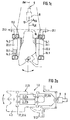
- FIGS. 1a to 1c illustrate in a schematically simplified representation an embodiment of the embodiment of an automatic clutch for rail vehicles, in particular an automatic train clutch 1, with a shock absorber arrangement comprising at least one device for damping vibrations 2 and 2.2 in three views.
- FIG. 1 a illustrates the view of the automatic train coupling 1 in the installed position in a rail vehicle or wagon 3, the view of it in the direction of the theoretical connecting axis A, theoretically for the coupling between two rail vehicles or wagons 3 to be coupled to one another.
- the wagon 3 is in this case shown only hinted.
- FIGS. 1b and 1c each show the views from the right and from above according to FIG. 1a. In FIGS.
- This comprises a coupling head 4, which is provided with a coupling profile 5 and has centering surfaces 6.
- a coupling head 4 which is provided with a coupling profile 5 and has centering surfaces 6.
- the two heads 4 interlock and are secured in this position by a locking system, not shown here in detail, which opens when coupling, closing or uncoupling the coupling profile.
- a coupling arm 10 is provided for transmitting the tensile forces from the coupling head 4 via a hinge pin 8 to a tension spring 9. This is not shown in detail here, but is only indicated with regard to its position by the dash-dotted line.
- the coupling head 4 is slidably mounted longitudinally. Also visible in FIG. 1c are so-called pre-compression springs 11, here in detail 11.1 and 11.2, which always press the coupling head 4 into a "long" position, which corresponds to the position ready for coupling.
- the pre-compression springs here the pre-compression springs 11.1 and 11.2, takes place symmetrically to the wagon axis A W , which coincides with the longitudinal axis of the coupling head 4 A LK .
- the pre-compression springs 11.1 and 11.2 are supported on a support device 12 which is connected to the rail vehicle or the wagon 3.
- the support device 12 In addition to carrying the coupling head 4, the support device 12 has the task of pushing it forward with a defined force and automatically returning it to the central position after a deflection. Furthermore, the possible deflection angle of the automatic coupling 1 with respect to the wagon axis A W or the theoretical connecting axis when coupling two rail vehicles or wagons 3 A V is theoretically represented by a double arrow.
- the automatic pull coupling 1 is at least one device for damping vibrations, in particular a shock absorber arrangement 2 for Compensation of the axial clearances and / or tolerances and / or wear in the Connection between automatic train coupling 1 and rail vehicle or Waggon 3 and / or the individual elements of the automatic train coupling 1 and the distance between the page buffers not shown in FIG. 1 and the Associated with bolts.
- the shock absorber arrangement 2 comprises two in the case shown Shock absorbers 2.1 and 2.2.
- the shock absorbers are devices for damping mechanical vibrations. These can be done differently his. As a rule, however, hydraulic shock absorbers are used. At This becomes the vibrational energy due to the friction of a liquid in heat transferred.
- the shock absorbers 2.1 and 2.2 are preferably used as so-called telescopic vibration dampers executed.
- These telescopic vibration dampers can For example, be configured as a 2-pipe damper or 1-pipe damper. This consist essentially of a working cylinder 13, here the working cylinders 13.1 and 13.2, in each of which a working piston 14.1 or 14.2, which has a here piston rod 15.1 or 15.2 not shown in detail with the rail vehicle or wagon 3 is connected, can slide up and down.
- the shock absorber arrangement 2 in particular the shock absorber 2.1, 2.2, connected to the coupling head 4 and is supported at least indirectly on the rail vehicle or wagon 3.
- the support on the rail vehicle or on wagon 3 usually takes place on the front edge 16 of the wagon plank 17. Since the coupling head 4 deflections corresponding to those shown Can experience double arrows, and for this purpose via a hinge pin 8 is rotatably mounted, the shock absorber assembly 2, in particular the shock absorbers 2.1 and 2.2 assigned resources, which are also a deflection of the individual Allow shock absorbers in a corresponding manner.
- the funds for this include in simplest case swivel joints, which the coupling between coupling head 4 and Shock absorber arrangement 2 or shock absorber arrangement 2 and rail vehicle or wagon 3 enable.
- These swivel joints are here for the shock absorber 2.1 designated with 20.1a, 20.1b and for the shock absorber 2.2 with 20.2a and 20.2b.
- the Swivel joints of a shock absorber 2.1 or 2.2 or a shock absorber arrangement 2.1 or 2.2 or the entire shock absorber arrangement 2 can be a so-called Rotating frame 19, here 19.1 and 19.2, each of which has a console 21, here 21.1 or 21.2, with the rail vehicle or wagon 3, in particular the Front edge 16 of the wagon plank 17, be connected.
- Another option is there in that the individual rotating frames 19.1 and 19.2 also in one store the used frame.
- the individual shock absorbers 2.1 and 2.2 are assigned symmetrically to the wagon axis A W and thus symmetrically to Longitudinal axis A LK of the coupling head 4.
- a coaxial design of the pre-compression springs 11.1 and 11.2 and the shock absorbers 2.1, 2.2, in particular the working cylinders 13.1, 13.2, is preferred to one another in all viewing planes.
- FIGS. 1a and 1b the arrangement according to FIGS. 1a and 1b takes place in a plane which can be described by the axis of the coupling arm A KA and a perpendicular to the latter, which, viewed in the installed position, is determined by the horizontal direction.
- shock absorbers 2.1 and 2.2 as a telescopic vibration damping device in the form of a 2-pipe damper
- the working cylinder 13.1 or 13.2 of a second cylinder 22.1 or 22.2 which serves as a storage container for a Pressure medium, preferably hydraulic oil, is used.
- a Pressure medium preferably hydraulic oil
- the shock absorbers 2.1 and 2.2 can be constantly with pressure medium, especially hydraulic oil be charged.
- means 23 for Control in particular to provide optional provision of the damping effect.
- the shock absorber 2.31 with a certain damping force for example due to a corresponding position of the clutch - "long” or “short” - activated in terms of its effect.
- the damping force is there the shock absorbers 2.31 and not shown here 2.32 are not required Pressure medium applied.
- the means 23 preferably comprise a pressure medium circuit 46, which can be designed as an open or closed circuit and has at least one inlet 47 to the shock absorber 2.31 and an outlet 48, a bypass line 24, a valve device 25, or in a further embodiment a shut-off device. Both options can be used alternatively or in Combination can be applied.
- the pressure medium in the bypass line 24 with the valve device 25 open directed i.e. the cylinder / piston device formed from the working cylinder 13 and piston 14 of shock absorber 2.31 is not pressurized.
- the bypass line 24 is blocked, see above that the pressure medium acts on the cylinder / piston unit of the shock absorber 2.31.
- Each shock absorber 2.31 of the shock absorber arrangement 2 is preferably such means 23 assigned.
- the high damping forces can with a relatively small work capacity, which is stored in the storage spring, controlled become.
- Fig. 3b alternatively illustrates a possibility of common control the shock absorbers 2.31a and 2.31b of a shock absorber subassembly 2.31 of the shock absorber arrangement 2.3, the means 23 here a shut-off device 26 in the process 48.31 or 48.32.
- the pressure medium circuit 46 is in this case as open Circuit designed. At least for filling the shock absorbers 2.31a and 2.31b an operating fluid feed pump 49 is required. Both shock absorbers 2.31a and 2.31b are fed via a common pressure medium supply system 46. In the event that the damping force is not required, no pressure medium is conveyed and the shut-off device 26 is open. The pressure medium flows out of the Shock absorbers 2.31a and 2.31b.
- shut-off device 26 is blocked and the operating medium feed pump 49 is in operation taken so that the pressure medium the cylinder / piston units of the shock absorbers 2.31a and 2.31b acted upon. It is also conceivable that the pressure medium supply system 46 together two shock absorber part arrangements 2.31 and not shown here 2.32 assign. The version with shut-off device 26 is also on a shock absorber transferable.
- the Shut-off device 26 in a drain line 48 preferably two shut-off devices 26.31 and 26.32 are provided, each in the drain lines 48.31 and 48.32 of the cylinder / piston devices of the shock absorbers 2.31 and 2.32 are arranged so that the pressure medium when locked in the working space of the cylinder / piston device is pressed and the pistons 14.31 and 14.32 acted upon.
- a pressure medium supply system Bypass line to provide a shut-off device in the bypass line, in which In the event of a desired damping effect, the bypass line through the shut-off device is blocked.
- the form springs 11.1 and 11.2 press the automatic coupling 1 the coupling head 4 always in the "long" position, which corresponds to the position ready for coupling, on the one hand if the damping effect is not provided, i.e. the shock absorber is virtually switched off, and also at Versions with shut-off valve 26 if this is still in the closed or locked position is at slow pre-pressure movement, because the damping force level be set by the speed of movement in the carriage axis can.
- the path between the individual positions the coupling head 4 - position "long” and position "short” - in addition to the game be dampened by an increased damping force.
- the way between the two Positions can be, for example, 60 mm and with the increased Damping force can be damped, for example, 20 tons.
- the pushing force is preloaded pre-compression springs 11.1 and 11.2 approx. 3000 N to 5000 N, so that a gentle coupling is possible even in tight arcs.
- the higher damping forces that would interfere with the coupling process act in the functional position of the Coupling head 4 opposite the coupling arm 10 "short" to the end of the axial play.
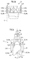
- FIGS. 2a to 2c illustrate in a schematically simplified representation, using an automatic pull coupling 1.2, a further possibility of the configuration according to the invention with a shock absorber arrangement 22, comprising at least one device for damping vibrations 2.2.
- the shock absorber arrangement comprises two shock absorber subassemblies 2.21 and 2.22, which have at least two shock absorbers or damping cylinders 2.21a, 2.21b and 2.22a, 2.22b.
- the arrangement of the shock absorber part arrangements 2.21 and 2.22 takes place symmetrically to the wagon axis A W or to the longitudinal axis of the coupling heads A LK .
- the remaining basic structure of the automatic clutch 1.2 corresponds to that described in FIG.
- shock absorber part arrangements 2.21 and 2.22 takes place coaxially with the pre-compression springs 11.21 and 11.22 or the wagon axis A W , which corresponds to the longitudinal axis of the coupling heads A LK .
- the individual damping cylinders 2.21a, 2.21b or 2.22a, 2.22b can be arranged in a common plane E when viewed in the vertical position according to FIG. 2b. This is a preferred embodiment, since it is the easiest to implement with regard to the bearings to be provided.
- shock absorber part arrangements 2.21 and 2.22 are also conceivable, in which the individual damping cylinders are arranged in vertical positions offset from one another when viewed in the installed position.
- connection of the individual damping cylinders 2.21a, 2.21b or 2.22a, 2.22b to be carried out independently of one another on the coupling head 4.2 and the console 21.2, in this case, however, the corresponding installation space required on the coupling head 4 to be taken into account and corresponding connecting means additionally to design.
- each of the damping cylinders 2.21a, 2.21b and 2.22a, 2.22b have their own operating and pressure medium supply systems each, for example, a separate bypass line with appropriate Assign tax opportunities.
- the damping cylinders are also conceivable a shock absorber part arrangement 2.21 or 2.22 a common Assign system, the systems of both shock absorber subassemblies 2.21 or 2.22 work independently of each other.
- a third option is both Shock absorber subassemblies 2.21 and 2.22 a jointly usable operating or Pressure medium supply system with appropriate means for optional provision assign the damping effect.
- the least expensive version Control engineering effort is characterized in that both shock absorber part arrangements 2.21 and 2.22 the same means of optional provision use the damping effect.
- the control of the means for optional The damping effect is provided depending on the one to be achieved Functional positions. In particular, for example, by a purely mechanical Coupling between an element which is in the functional position "lang" occupies a corresponding position and the means for optional provision the damping effect 23, in particular, for example, the adjusting device a valve device 25, a corresponding control can be achieved. By the mechanical coupling is then forcibly actuated accordingly the valve device 25.
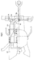
- FIGS. 4a-4c illustrate one possible one based on three functional positions Embodiment of an automatic train coupling, which according to the invention with can be equipped with a shock absorber arrangement.
- the automatic train coupling is designated 1.4.
- the basic structure corresponds to that in FIGS. 1 and 2 schematically reproduced, which is why the same reference numerals for the same elements be used.
- the page buffers 45 are also indicated.
- the automatic train coupling assigned to a rail vehicle, in particular wagon 3 1.4 exists in addition to the modules coupling head 4.4, coupling arm 10.4 from a bolt system 7.4 and an automatic changeover 28, at least one Actuating system 29 for the automatic changeover 28 and the locking system 7.4 and a support device 12.4.
- the locking system 7.4 has the task of coupling the profile of the two together Coupling heads 4.41 and 4.42, each assigned to a wagon 3.41 are to be closed and the profile opened when uncoupling.
- This includes one Bolt 35, a latch pawl 37 with a stop C, a pawl spring 30 and one Latch lever 41, which acts on the latch 35.
- the bolt 35 of the bolt system 7.4 is usually in the coupling head 4.4 pushed back to make room for the mixed pull coupling, not shown here to accomplish.
- the bolt 35 is then pushed forward.
- the coupling center, i.e. the coupling head 4.4 is in front of the Page buffer level E.
- the dome-ready position is determined by an arrangement determined by coupling head 4.4 and hinge pin 8.4 to each other, which by a relative movement between coupling head 4.4 and coupling arm 10.4 changed can be and describes a first limit position.
- the spacer 36 of the Automatic changeover 28 has not occurred in this position, the latch 35 is on his pushed back position and a coupled with this latch pawl 37 pushed up by a pedal 38.
- the claw then pushes in Mating coupling not shown in this figure, i.e. the coupling profile 5 of Coupling head 4 of the counter clutch, the pedal 38, and tensioned a storage spring 39 and an intermediate spring 40.
- the storage spring 39 is supported on Coupling head 4.4 and the pedal 38, which is rotatably mounted on the coupling head 4.4 is, from.
- the intermediate spring 40 is between bolt system 7.4 and pedal 38 arranged. This acts on the locking lever 41, which then locks the bolt 35 in Presses the direction of the connecting axis up to the coupling profile 5.4. Another one Advance of the bolt 35 is not possible, since this is the small claw of the introduced Counter coupling opposes.
- the latch pawl 37 is up to the stop C brought and can not come up. Through the pivoting locking lever 41 a slide 42 released and pulled by a return spring 43.
- the Pin of the spacer 36 makes an idle in the slide link 44th 4b are then in the coupled state in the functional position "long" according to FIG two latches 35 of the coupling 1.4 and 35.2 of the mating coupling 1.42 all the way into that Profiles 5.4 or 5.42 pressed forward, the latch 37 has engaged before the stop C. and the latch 35 is secured.
- the return spring 43 pulls on the slide 42 and presses on the spacer 36 by means of a pin D. This cannot occur, because it is blocked by the contact point E on the coupling arm 10.4.
- the individual elements are only for the automatic train coupling 1.4 shown. How the complementary coupling works 1.42 is done analogously.
- the automatic changeover 28 serves to set the functional positions "long” or “short".
- the shortening is due to the spacer 36, which is between the Coupling head 4.4 and the coupling arm 10.4 occurs.
- the functional sequence can be described as follows: When pressing on vehicles 3.41 or 3.42, the coupling head 4.4 or 4.42 pressed back onto the coupling arm 10.4 or 10.42, not shown here and opens the space for the spacer 36 or 36.2. It can come up now.
- the automatic train coupling 1.4 or 1.42 is in the "short" function position brought, as shown in Fig. 4c.
- a corresponding actuation system 29 is provided from the vehicle side.
- This essentially fulfills the functions of unlocking, long position Coupling, for example when driving through narrow bends, and holding in the Butt position, i.e. when coupling is no longer possible. It is enough to Uncouple the vehicles, only unlock one of the two clutches.
- the operating handle is always on the same side of the vehicle, so that there is the possibility of actuating both at each coupling point Operate sides of the train.
- the support devices of the two together in Automatic clutches 1.4 and 1.42, which can be engaged, have the task of Coupling head 4.4 or 4.42 to carry it forward with a defined force press and return it automatically to its central position after a deflection.
- at least two are on the sides the coupling head 4.4 or 4.42 arranged compression springs in the form of the pre-compression springs provided that the forward and weight force of the coupling head 4.4 or 4.42 transmitted to the chassis of the vehicle via the coupling arm.
- the automatic train couplings 1 or 1.4 cable couplings Air line couplings and / or electrical couplings assigned, which, however, in Individuals are not shown in the figures.
- the air couplings are on Coupling head 4.4 arranged below the coupling longitudinal axis and are in the starting position with the sealing surface in front of the coupling center. This includes, for example, an air tube with a sealing ring and concentrically arranged grippers, which get caught in the coupled state and the under and overpressure Ensure tightness. When coupling, the air couplings are pushed back, until the grippers have centered.
- the element of the mixed pull coupling 31 shown in FIG. 4d essentially consists from a hand lever 32, which together with a crank 33 on the coupling head 4.4 is mounted, a handlebar 34, which is mounted at a point B on the crank 33 and is connected at point C to a tension bracket 50 and a dead center spring 51 and a return spring 52.
- the drawbar lies 50 of the mixed pull coupling 31 behind the profile 5.4 of the automatic pull coupling 1.4.
- the mixed train coupling provides a second additional coupling system represents which is integrated in the automatic train coupling 1.4 to during a transition period also includes cars with an equipped screw coupling system couple.
- the Hand lever 32 turned up and takes crank 33 via contact points D and E.
- FIG. 5 illustrates a version of an automatic coupling for rail vehicles with a shock absorber arrangement in the form of a liquid damper arrangement, comprising at least one shock absorber 2.5.
- the shock absorber 2.5 is connected to the coupling head 4.5 and at least indirectly to the rail vehicle assigned to the coupling head 4.5.
- a corresponding support device, here designated 53 is provided.
- the support device 53 comprises a centering device 55 mounted in the frame unit 54 with a centering arm 56 and means for transmitting at least the pressure and / or weight forces of the coupling head 4.5 via the centering arm 56 to the chassis of the rail vehicle.
- the means for transmission have at least one tension spring device, which is supported at least indirectly on the coupling head 4.5 and the centering arm 56, and in each case a pivot bearing arrangement between the coupling head 4.5 and centering arm 56 and the chassis of the vehicle.
- the compression spring device is arranged eccentrically in the installed position in a view from above with respect to the center axis A M of the coupling head.
- the force transmission takes place essentially on these elements via the pivot bearing arrangements, which enable the centering arm 56 to be movable relative to the coupling head 4.5 by at least two axes, a horizontal axis and a vertical axis, when viewed in the installed position.
- the compression spring device of the required supporting device 53 is preferably assigned to the coupling head 4.5 in an area which is limited in the horizontal direction by the theoretical connecting axis of the rail vehicles to be coupled, viewed in the installation position, and a side buffer which is assigned to the coupling head on the side, which is directed away from the coupling head of the automatic train coupling to be coupled.
- the support device in particular the compression spring device, is viewed in the horizontal position in the installed position, with respect to the center axis A M of the coupling head below it and, viewed in the horizontal direction, is preferably arranged entirely in a region which is defined by the center axis of the coupling head 4.5 and the line of symmetry of the on the rail vehicle on the side of the coupling head facing away from the side of the coupling head to be coupled, the area below the central axis is essentially free of that in components of the support device.
Landscapes
- Engineering & Computer Science (AREA)
- Mechanical Engineering (AREA)
- Fluid-Damping Devices (AREA)
- Vibration Prevention Devices (AREA)
Abstract
Description
- Fig. 1a-1c
- verdeutlichen in schematisch vereinfachter Darstellung eine Ausführung der erfindungsgemäßen Ausgestaltung einer automatischen Kupplung für Schienenfahrzeuge mit einer Stoßdämpferanordnung, umfassend zwei Stoßdämpferteilanordnungen mit jeweils einem Stoßdämpfer;
- Fig. 2a-2c
- verdeutlichen in schematisch vereinfachter Darstellung eine Ausführung der erfindungsgemäßen Ausgestaltung einer automatischen Kupplung für Schienenfahrzeuge mit einer Stoßdämpferanordnung, umfassend zwei Stoßdämpferteilanordnungen mit jeweils einer Mehrzahl von Stoßdämpfern;
- Fig. 3a-3b
- verdeutlichen beispielhaft in schematisch vereinfachter Darstellung zwei Möglichkeiten der Zuordnung von Mitteln zur wahlweisen Bereitstellung der Dämpfungswirkung;
- Fig. 4a-4d
- verdeutlicht in schematisch vereinfachter Darstellung beispielhaft eine mögliche Ausgestaltung einer automatischen Zugkupplung, welche zur erfindungsgemäßen Ausgestaltung mit einer Dämpfungsanordnung geeignet ist, in drei Funktionsstellungen;
- Fig. 5
- verdeutlicht in schematisch vereinfachter Darstellung eine erfindungsgemäße Ausführung einer automatischen Kupplung für Schienenfahrzeuge mit einer unsymmetrischen Stoßdämpferanordnung, umfassend lediglich eine Stoßdämpferteilanordnung.
- 1, 1.2, 1.4
- automatische Zugkupplung
- 2, 2.3
- Vorrichtung zur Dämpfung von Schwingungen, Stoßdämpferanordnung
- 2.1, 2.2, 2.21, 2.22, 2.31
- Stoßdämpferteilanordnung
- 2.1, 2.2, 2.21a, 2.21b, 2.22a, 2.22b, 2.31a, 2.32b, 2.5
- Stoßdämpfer
- 3, 3.4
- Schienenfahrzeug bzw. Waggon
- 4, 4.4, 4.42
- Kupplungskopf
- 4.5 5, 5.4, 5.42
- Kupplungsprofil
- 6
- Zentrierflächen
- 7, 7.4
- Riegelsystem
- 8, 8.4
- Gelenkbolzen
- 9
- Zugfeder
- 10, 10.4, 10.42
- Kupplungsarm
- 11, 11.1, 11.2
- Vordruckfedern
- 12, 12.4
- Abstützvorrichtung
- 13.1, 13.2
- Arbeitszylinder
- 14.1, 14.2 14.31, 14.32
- Kolben
- 15.1, 15.2
- Kolbenstange
- 16
- Vorderkante Waggonbohle
- 17
- Waggonbohle
- 18
- Mittel zur Realisierung einer Auslenkung der Stoßdämpferanordnung
- 19, 19.1, 19.2
- Drehrahmen
- 20.1a, 20.2a, 20.1b, 20.2b
- Drehgelenke
- 21, 21.1, 21.2
- Konsole
- 22a, 22b
- zweiter Zylinder
- 23
- Mittel zur wahlweisen Bereitstellung der Dämpfungswirkung
- 24
- Bypassleitung
- 25
- Ventileinrichtung
- 26
- Absperreinrichtung
- 27
- Rahmen
- 28
- Umstellautomatik
- 29
- Betätigungssystem für Umstellautomatik und Riegelsystem
- 30
- Klinkenfeder
- 31
- Gemischtzugkupplung
- 32
- Handhebel
- 33
- Kurbel
- 34
- Lenker
- 35
- Riegel
- 36
- Distanzstück
- 37
- Riegelklinke
- 38
- Pedal
- 39
- Speicherfeder
- 40
- Zwischenfeder
- 41
- Riegelhebel
- 42
- Schieber
- 43
- Rückholfeder
- 44
- Schieberkulisse
- 45
- Seitenpuffer
- 46
- Druckmittelkreislauf
- 47, 47.31, 47.32
- Zulauf
- 48, 48.31, 48.32
- Ablauf
- 49
- Betriebsmittelförderpumpe
- 50
- Zugbügel
- 51
- Totpunktfeder
- 52
- Rückzugsfeder
- 53
- Abstützvorrichtung
- 54
- Rahmeneinheit
- 55
- Zentriervorrichtung
- 56
- Zentrierarm
Claims (18)
- Automatische Kupplung für Schienenfahrzeuge, insbesondere automatische Zugkupplung1.1. mit einem, über einen Kupplungsarm (10, 10.4) an einer Zugfeder (9) an einem Schienenfahrzeug (3, 3.4, 3.42) angelenkten und gegenüber dem Kupplungsarm (10, 10.4) in Einbaulage in Richtung der theoretischen Verbindungsachse AVtheoretisch zwischen den miteinander zu kuppelnden Schienenfahrzeugen betrachtet verschiebbaren Kupplungskopf (4, 4.4, 4.42); gekennzeichnet durch die folgenden Merkmale:1.2 mit einer Stoßdämpferanordnung in Form einer Flüssigkeitsdämpferanordnung (2, 2.3), umfassend wenigstens einen Stoßdämpfer (2.1, 2.2, 2.21a, 2.21b, 2.22a, 2.22b, 2.31, 2.31a, 2.31b);1.3 der Stoßdämpfer (2.1, 2.2, 2.21a, 2.21b, 2.22a, 2.22b, 2.31, 2.31a, 2.31b) ist mit dem Kupplungskopf (4, 4.4, 4.42) und wenigstens mittelbar mit dem, dem Kupplungskopf (4, 4.2, 4.42) zugeordneten Schienenfahrzeug (3, 3.4, 3.42) verbunden.
- Automatische Zugkupplung nach Anspruch 1, dadurch gekennzeichnet, daß der einzelne Stoßdämpfer (2.1, 2.2, 2.21a, 2.21b, 2.22a, 2.22b, 2.31, 2.31a, 2.31b) als Teleskopdämpfer ausgeführt ist.
- Automatische Zugkupplung nach Anspruch 1 oder 2, gekennzeichnet durch die folgenden Merkmale:3.1 die Stoßdämpferanordnung (2, 2.3) weist wenigstens zwei Stoßdämpferteilanordnungen (2.1, 2.2, 2.21, 2.22, 2.31, 2.32), umfassend wenigstens jeweils einen Stoßdämpfer (2.1, 2.2, 2.21a, 2.21b, 2.22a, 2.22b, 2.31, 2.31a, 2.31b) auf;3.2 die Stoßdämpferteilanordnungen (2.1, 2.2, 2.21, 2.22, 2.31, 2.32) sind symmetrisch zueinander ausgestaltet und in Einbaulage in Bezug auf die theoretische Verbindungsachse AVtheoretisch zwischen den miteinander zu kuppelnden Schienenfahrzeugen betrachtet beidseitig symmetrisch zum Kupplungskopf (4, 4.4, 4.42), insbesondere zur Längsachse ALK des Kupplungskopfes (4, 4.4, 4.42) angeordnet.
- Automatische Zugkupplung nach einem der Ansprüche 1 bis 3, dadurch gekennzeichnet, daß die Stoßdämpferanordnung (2, 2.3) eine Vielzahl von Stoßdämpfern (2.1, 2.2, 2.21a, 2.21b, 2.22a, 2.22b, 2.31, 2.31a, 2.31b) aufweist.
- Automatische Zugkupplung nach einem der Ansprüche 1 bis 4, gekennzeichnet durch die folgenden Merkmale:5.1 mit einer Abstützvorrichtung (12), umfassend wenigstens zwei Vordruckfedern (11.1, 11.2) zur Beaufschlagung des Kupplungskopfes (4, 4.4, 4.42) mit einer definierten Kraft und selbsttätigen Rückführung des Kupplungskopfes (4, 4.4, 4.42) nach einer Auslenkung in seine Mittellage;5.2 die Vordruckfedern (11.1, 11.2) sind beidseitig des Kupplungskopfes (4, 4.4, 4.42) angeordnet;5.3 die Stoßdämpfer (2.1, 2.2, 2.21a, 2.21b, 2.22a, 2.22b, 2.31, 2.31a, 2.31b) sind jeweils parallel zu der Parallelführung Kupplungskopf und Achse (11.1, 11.2) angeordnet.
- Automatische Zugkupplung nach einem der Ansprüche 1 bis 5, dadurch gekennzeichnet, daß jeder einzelne Stoßdämpfer (2.1, 2.2, 2.21a, 2.21b, 2.22a, 2.22b, 2.31, 2.31a, 2.31b) wenigstens mittelbar über ein Drehgelenk (20.1a, 20.2a, 20.1b, 20.2b) am Kupplungskopf (4, 4.4, 4.42) und/oder dem Schienenfahrzeug (3, 3.4, 3.42) angelenkt ist.
- Automatische Zugkupplung nach Anspruch 6, dadurch gekennzeichnet, daß bei Ausführung der Stoßdämpferanordnung (2, 2.3) mit zwei Stoßdämpferteilanordnungen (2.1, 2.2, 2.21, 2.22, 2.31, 2.32) mit mehreren Stoßdämpfern (2.1, 2.2, 2.21a, 2.21b, 2.22a, 2.22b, 2.31, 2.31a, 2.31b) diese wenigstens auf der Schienenfahrzeugseite in einem Drehrahmen (19) gelagert sind.
- Automatische Zugkupplung nach einem der Ansprüche 6 oder 7, dadurch gekennzeichnet, daß bei Ausführung der Stoßdämpferanordnung (2, 2.3) mit zwei Stoßdämpferteilanordnungen (2.1, 2.2, 2.21, 2.22, 2.31, 2.32) den Stoßdämpferteilanordnungen (2.1, 2.2, 2.21, 2.22, 2.31, 2.32) jeweils eine, am Schienenfahrzeug (3, 3.4, 3.42) befestigbare Konsole (21, 21.1, 21.2) zugeordnet ist und die Anlenkung an der Konsole (21, 21.1, 21.2) erfolgt.
- Automatische Zugkupplung nach einem der Ansprüche 6 oder 7, dadurch gekennzeichnet, daß bei Ausführung der Stoßdämpferanordnung (2, 2.3) mit zwei Stoßdämpferteilanordnungen (2.1, 2.2, 2.21, 2.22, 2.31, 2.32) beiden Stoßdämpferteilanordnungen (2.1, 2.2, 2.21, 2.22, 2.31, 2.32) eine, am Schienenfahrzeug befestigbare gemeinsame Konsole (21) zugeordnet ist und die Anlenkung an der Konsole (21) erfolgt.
- Automatische Zugkupplung nach einem der Ansprüche 1 oder 2, gekennzeichnet durch die folgenden Merkmale:10.1 es ist ein Stoßdämpfer (2.5) vorgesehen, welcher mit dem Kupplungskopf und wenigstens mittelbar mit dem, dem Kupplungskopf (4.5) zugeordneten Schienenfahrzeug verbunden ist;10.2 mit einer Abstützvorrichtung (53), umfassend eine mit dem Schienenfahrzeug (3) koppelbare Rahmeneinheit (54) und einer in der Rahmeneinheit (54) gelagerten Zentriervorrichtung (55), umfassend einen Zentrierarm (56);10.3 mit einer Druckfedereinrichung zur Übertragung wenigstens der Druck- und/oder Gewichtskräfte des Kupplungskopfes (4.5) über den Zentrierarm (56) auf den Chassis des Schienenfahrzeuges;10.4 die Druckfedereinrichtung ist in Einbaulage in einer Ansicht von oben betrachtet bezogen auf die Mittenachse (AM) des Kupplungskopfes außermittig angeordnet.
- Automatische Zugkupplung nach einem der Ansprüche 1 bis 10, dadurch gekennzeichnet, daß der Stoßdämpferanordnung (2, 2.3) Mittel zur wahlweisen Bereitstellung der Dämpfungswirkung (23) zugeordnet sind.
- Automatische Zugkupplung nach Anspruch 11, gekennzeichnet durch die folgende Merkmale:12.1 die Mittel (23) umfassen wenigstens ein der Stoßdämpferanordnung (2, 2.3) zugeordnetes Druckmittelversorgungssystem (46);12.2 das Druckmittelversorgungssystem (46) umfaßt wenigstens einen Zulauf (47) und einen Ablauf (48) zum einzelnen Stoßdämpfer (2.1, 2.2, 2.21a, 2.21b, 2.22a, 2.22b, 2.31, 2.31a, 2.31b) und Mittel zur wahlweisen Beaufschlagung der Stoßdämpfer (2.1, 2.2, 2.21a, 2.21b, 2.22a, 2.22b, 2.31, 2.31a, 2.31b) mit Druckmittel.
- Automatische Zugkupplung nach Anspruch 12, dadurch gekennzeichnet, daß die Mittel zur wahlweisen Beaufschlagung der Stoßdämpfer (2.1, 2.2, 2.21a, 2.21b, 2.22a, 2.22b, 2.31, 2.31a, 2.31b) mit Druckmittel eine Bypassleitung (25) umfassen.
- Automatische Zugkupplung nach Anspruch 12, gekennzeichnet durch folgende Merkmale:14.1 das Druckmittelversorgungssystem (46) ist als offener Kreislauf ausgeführt;14.2 die Mittel zur wahlweisen Beaufschlagung der Stoßdämpfer (2.1, 2.2, 2.21a, 2.21b, 2.22a, 2.22b, 2.31, 2.31a, 2.31b) umfassen eine, im Zulauf (47, 47.31, 47.32) zu den einzelnen Stoßdämpfern (2.1, 2.2, 2.21a, 2.21b, 2.22a, 2.22b, 2.31, 2.31a, 2.31b) angeordente Betriebsmittelförderpumpe (49) und eine, im Ablauf (48, 48.31, 48.32) angeordnete Absperreinrichtung (26).
- Automatische Zugkupplung nach einem der Ansprüche 11 bis 14, dadurch gekennzeichnet, daß jedem Stoßdämpfer (2.1, 2.2, 2.21a, 2.21b, 2.22a, 2.22b, 2.31, 2.31a, 2.31b) der Stoßdämpferanordnung (2, 2.3) die Mittel zur wahlweisen Bereitstellung der Dämpfungswirkung (23) zugeordnet sind.
- Automatische Zugkupplung nach einem der Ansprüche 11 bis 14, dadurch gekennzeichnet, daß den Stoßdämpfern (2.1, 2.2, 2.21a, 2.21b, 2.22a, 2.22b, 2.31, 2.31a, 2.31b) jeder Stoßdämpferteilanordnung der Stoßdämpferanordnung (2, 2.3) oder den Stoßdämpfern (2.1, 2.2, 2.21a, 2.21b, 2.22a, 2.22b, 2.31, 2.31a, 2.31b) der gesamten Stoßdämpferanordnung (2, 2.3) die Mittel zur wahlweisen Bereitstellung der Dämpfungswirkung (23) gemeinsam zugeordnet sind.
- Automatische Zugkupplung nach einem der Ansprüche 1 bis 16, gekennzeichnet durch die folgenden Merkmale:17.1 mit einem Riegelsystem (7, 7.4) zum Verschließen und Öffnen der Profile (5, 5.4, 5.42) der beiden miteinander zu kuppelnden Kupplungsköpfe (4, 4.4, 4.42), die jeweils einem Schienenfahrzeug (3, 3.4, 3.42), insbesondere Waggon zugeordnet sind;17.2 einer Umstellautomatik (28) zur Realisierung zweier Funktionsstellungen des Kupplungsarmes (10, 10.4) "lang" bzw. "kurz";17.3 mit wenigstens einem Betätigungssystem (29) für die Umstellautomatik (28) und das Riegelsystem (7, 7.4),17.4 einer Luftkupplung für die Hauptluftleitung,17.5 einer Gemischtzugkupplung (31) und17.6 einer Gemischtluftkupplung.
- Automatische Zugkupplung nach Anspruch 17, gekennzeichnet durch die folgenden Merkmale:18.1 mit einer Luftkupplung für die Hauptluftbehälterleitung und18.2 mit einer Elektrokupplung;
Applications Claiming Priority (4)
| Application Number | Priority Date | Filing Date | Title |
|---|---|---|---|
| DE19933996 | 1999-07-20 | ||
| DE19933996 | 1999-07-20 | ||
| DE19947829A DE19947829A1 (de) | 1999-07-20 | 1999-10-05 | Automatische Kupplung für Schienenfahrzeuge, insbesondere automatische Zugkupplung |
| DE19947829 | 1999-10-05 |
Publications (2)
| Publication Number | Publication Date |
|---|---|
| EP1070646A1 true EP1070646A1 (de) | 2001-01-24 |
| EP1070646B1 EP1070646B1 (de) | 2004-02-18 |
Family
ID=26054259
Family Applications (1)
| Application Number | Title | Priority Date | Filing Date |
|---|---|---|---|
| EP20000114198 Expired - Lifetime EP1070646B1 (de) | 1999-07-20 | 2000-07-14 | Automatische Kupplung für Schienenfahrzeuge, insbesondere automatische Zugkupplung |
Country Status (1)
| Country | Link |
|---|---|
| EP (1) | EP1070646B1 (de) |
Cited By (1)
| Publication number | Priority date | Publication date | Assignee | Title |
|---|---|---|---|---|
| CN110307933A (zh) * | 2019-07-16 | 2019-10-08 | 西南交通大学 | 一种铁路车辆车钩力静态标定试验台 |
Citations (4)
| Publication number | Priority date | Publication date | Assignee | Title |
|---|---|---|---|---|
| US3139193A (en) * | 1962-04-09 | 1964-06-30 | Acf Ind Inc | Long travel draft gear |
| DE3240845A1 (de) * | 1982-11-05 | 1984-05-10 | Messerschmitt-Bölkow-Blohm GmbH, 8000 München | Stabilisierungssystem fuer spurgefuehrte fahrzeugverbaende |
| DE19636225A1 (de) * | 1996-09-06 | 1998-03-12 | Dellner Couplers Ab | Mittelpufferkupplung |
| DE19757621A1 (de) * | 1997-12-23 | 1999-07-01 | Knorr Bremse Systeme | Automatische Zugkupplung |
-
2000
- 2000-07-14 EP EP20000114198 patent/EP1070646B1/de not_active Expired - Lifetime
Patent Citations (4)
| Publication number | Priority date | Publication date | Assignee | Title |
|---|---|---|---|---|
| US3139193A (en) * | 1962-04-09 | 1964-06-30 | Acf Ind Inc | Long travel draft gear |
| DE3240845A1 (de) * | 1982-11-05 | 1984-05-10 | Messerschmitt-Bölkow-Blohm GmbH, 8000 München | Stabilisierungssystem fuer spurgefuehrte fahrzeugverbaende |
| DE19636225A1 (de) * | 1996-09-06 | 1998-03-12 | Dellner Couplers Ab | Mittelpufferkupplung |
| DE19757621A1 (de) * | 1997-12-23 | 1999-07-01 | Knorr Bremse Systeme | Automatische Zugkupplung |
Cited By (2)
| Publication number | Priority date | Publication date | Assignee | Title |
|---|---|---|---|---|
| CN110307933A (zh) * | 2019-07-16 | 2019-10-08 | 西南交通大学 | 一种铁路车辆车钩力静态标定试验台 |
| CN110307933B (zh) * | 2019-07-16 | 2024-03-29 | 西南交通大学 | 一种铁路车辆车钩力静态标定试验台 |
Also Published As
| Publication number | Publication date |
|---|---|
| EP1070646B1 (de) | 2004-02-18 |
Similar Documents
| Publication | Publication Date | Title |
|---|---|---|
| EP4330110B1 (de) | Automatische zugkupplung und verfahren zum entkuppeln einer automatischen zugkupplung | |
| EP4330109B1 (de) | Automatische zugkupplung und verfahren zum entkuppeln einer automatischen zugkupplung | |
| EP3104037B1 (de) | Zug-/stosseinrichtung, insbesondere für mittelpufferkupplungen von spurgeführten fahrzeugen | |
| EP1580093B1 (de) | Fahrzeug, insbesondere spurgeführtes Fahrzeug, mit gelenkig verbundenen Wagenkästen | |
| EP4121333B1 (de) | Kupplungsanordnung | |
| DE202020005519U1 (de) | Elektrokupplung für ein spurgebundenes Fahrzeug, automatische Kupplung mit einer derartigen Elektrokupplung | |
| EP2322403A2 (de) | Automatische Kupplung für Schienenfahrzeuge mit Seitenpuffern | |
| EP1925523B1 (de) | Kupplungsanlenkung für einen Wagenkasten eines mehrgliedrigen Fahrzeuges | |
| DE102009035910A1 (de) | Doppelkupplung | |
| WO2024231240A1 (de) | Handentkuppeleinrichtung, automatische zugkupplung und schienenfahrzeugrahmen mit einer automatischen zugkupplung | |
| WO2023160923A1 (de) | Automatische zugkupplung, spurgeführtes fahrzeug mit einer solchen automatischen zugkupplung sowie verfahren zum entkuppeln von zwei miteinander gekuppelten automatischen zugkupplungen | |
| EP1070646B1 (de) | Automatische Kupplung für Schienenfahrzeuge, insbesondere automatische Zugkupplung | |
| WO2022214246A1 (de) | Schienenfahrzeug mit mittelpufferkupplung | |
| EP3750770B1 (de) | Kupplung, insbesondere für ein schienenfahrzeug | |
| DE19947829A1 (de) | Automatische Kupplung für Schienenfahrzeuge, insbesondere automatische Zugkupplung | |
| DE4118529C2 (de) | Zug- und Stoßeinrichtung für kurzgekuppelte Schienenfahrzeuge | |
| DE19921510B4 (de) | Abstützvorrichtung für eine automatische Zugkupplung | |
| DE102020204445A1 (de) | Elektrokupplung für ein spurgebundenes Fahrzeug, automatische Kupplung mit einer derartigen Elektrokupplung und Verfahren zum Kuppeln und Entkuppeln | |
| DE102025135544A1 (de) | Kupplungsanordnung und Verfahren zur Einleitung einer Notbremsung | |
| DE102024127020A1 (de) | Kupplungsanordnung | |
| DE102023121378A1 (de) | Kupplungsanordnung, insbesondere Hybridkupplungsanordnung | |
| EP3371029A1 (de) | Verdrehgesicherte anlenkung zum gelenkigen verbinden einer kupplungsstange mit einem wagenkasten | |
| WO2025103971A1 (de) | Automatische zugkupplung und kupplungsanordnung | |
| DE102023127092A1 (de) | Kupplungsanordnung, insbesondere Hybridkupplungsanordnung | |
| DE202004020784U1 (de) | Fahrzeug, insbesondere spurgeführtes Fahrzeug, mit gelenkig verbundenen Wagenkästen |
Legal Events
| Date | Code | Title | Description |
|---|---|---|---|
| PUAI | Public reference made under article 153(3) epc to a published international application that has entered the european phase |
Free format text: ORIGINAL CODE: 0009012 |
|
| AK | Designated contracting states |
Kind code of ref document: A1 Designated state(s): DE FR GB SE |
|
| AX | Request for extension of the european patent |
Free format text: AL;LT;LV;MK;RO;SI |
|
| 17P | Request for examination filed |
Effective date: 20010724 |
|
| AKX | Designation fees paid |
Free format text: DE FR GB SE |
|
| 17Q | First examination report despatched |
Effective date: 20020913 |
|
| GRAP | Despatch of communication of intention to grant a patent |
Free format text: ORIGINAL CODE: EPIDOSNIGR1 |
|
| GRAS | Grant fee paid |
Free format text: ORIGINAL CODE: EPIDOSNIGR3 |
|
| GRAA | (expected) grant |
Free format text: ORIGINAL CODE: 0009210 |
|
| AK | Designated contracting states |
Kind code of ref document: B1 Designated state(s): DE FR GB SE |
|
| PG25 | Lapsed in a contracting state [announced via postgrant information from national office to epo] |
Ref country code: FR Free format text: LAPSE BECAUSE OF FAILURE TO SUBMIT A TRANSLATION OF THE DESCRIPTION OR TO PAY THE FEE WITHIN THE PRESCRIBED TIME-LIMIT Effective date: 20040218 Ref country code: GB Free format text: LAPSE BECAUSE OF FAILURE TO SUBMIT A TRANSLATION OF THE DESCRIPTION OR TO PAY THE FEE WITHIN THE PRESCRIBED TIME-LIMIT Effective date: 20040218 |
|
| REG | Reference to a national code |
Ref country code: GB Ref legal event code: FG4D Free format text: NOT ENGLISH |
|
| REF | Corresponds to: |
Ref document number: 50005303 Country of ref document: DE Date of ref document: 20040325 Kind code of ref document: P |
|
| PG25 | Lapsed in a contracting state [announced via postgrant information from national office to epo] |
Ref country code: SE Free format text: LAPSE BECAUSE OF FAILURE TO SUBMIT A TRANSLATION OF THE DESCRIPTION OR TO PAY THE FEE WITHIN THE PRESCRIBED TIME-LIMIT Effective date: 20040518 |
|
| GBV | Gb: ep patent (uk) treated as always having been void in accordance with gb section 77(7)/1977 [no translation filed] |
Effective date: 20040218 |
|
| PLBE | No opposition filed within time limit |
Free format text: ORIGINAL CODE: 0009261 |
|
| STAA | Information on the status of an ep patent application or granted ep patent |
Free format text: STATUS: NO OPPOSITION FILED WITHIN TIME LIMIT |
|
| EN | Fr: translation not filed | ||
| 26N | No opposition filed |
Effective date: 20041119 |
|
| PGFP | Annual fee paid to national office [announced via postgrant information from national office to epo] |
Ref country code: DE Payment date: 20100922 Year of fee payment: 11 |
|
| PG25 | Lapsed in a contracting state [announced via postgrant information from national office to epo] |
Ref country code: DE Free format text: LAPSE BECAUSE OF NON-PAYMENT OF DUE FEES Effective date: 20120201 |
|
| REG | Reference to a national code |
Ref country code: DE Ref legal event code: R119 Ref document number: 50005303 Country of ref document: DE Effective date: 20120201 |