EP1070603A2 - Retaining assembly for an axle hub and bearing assembly - Google Patents
Retaining assembly for an axle hub and bearing assembly Download PDFInfo
- Publication number
- EP1070603A2 EP1070603A2 EP00114983A EP00114983A EP1070603A2 EP 1070603 A2 EP1070603 A2 EP 1070603A2 EP 00114983 A EP00114983 A EP 00114983A EP 00114983 A EP00114983 A EP 00114983A EP 1070603 A2 EP1070603 A2 EP 1070603A2
- Authority
- EP
- European Patent Office
- Prior art keywords
- washer
- assembly
- spindle
- end nut
- set forth
- Prior art date
- Legal status (The legal status is an assumption and is not a legal conclusion. Google has not performed a legal analysis and makes no representation as to the accuracy of the status listed.)
- Withdrawn
Links
Images


Classifications
-
- B—PERFORMING OPERATIONS; TRANSPORTING
- B60—VEHICLES IN GENERAL
- B60B—VEHICLE WHEELS; CASTORS; AXLES FOR WHEELS OR CASTORS; INCREASING WHEEL ADHESION
- B60B27/00—Hubs
- B60B27/02—Hubs adapted to be rotatably arranged on axle
-
- F—MECHANICAL ENGINEERING; LIGHTING; HEATING; WEAPONS; BLASTING
- F16—ENGINEERING ELEMENTS AND UNITS; GENERAL MEASURES FOR PRODUCING AND MAINTAINING EFFECTIVE FUNCTIONING OF MACHINES OR INSTALLATIONS; THERMAL INSULATION IN GENERAL
- F16C—SHAFTS; FLEXIBLE SHAFTS; ELEMENTS OR CRANKSHAFT MECHANISMS; ROTARY BODIES OTHER THAN GEARING ELEMENTS; BEARINGS
- F16C25/00—Bearings for exclusively rotary movement adjustable for wear or play
- F16C25/06—Ball or roller bearings
-
- F—MECHANICAL ENGINEERING; LIGHTING; HEATING; WEAPONS; BLASTING
- F16—ENGINEERING ELEMENTS AND UNITS; GENERAL MEASURES FOR PRODUCING AND MAINTAINING EFFECTIVE FUNCTIONING OF MACHINES OR INSTALLATIONS; THERMAL INSULATION IN GENERAL
- F16C—SHAFTS; FLEXIBLE SHAFTS; ELEMENTS OR CRANKSHAFT MECHANISMS; ROTARY BODIES OTHER THAN GEARING ELEMENTS; BEARINGS
- F16C35/00—Rigid support of bearing units; Housings, e.g. caps, covers
- F16C35/04—Rigid support of bearing units; Housings, e.g. caps, covers in the case of ball or roller bearings
- F16C35/06—Mounting or dismounting of ball or roller bearings; Fixing them onto shaft or in housing
- F16C35/067—Fixing them in a housing
-
- F—MECHANICAL ENGINEERING; LIGHTING; HEATING; WEAPONS; BLASTING
- F16—ENGINEERING ELEMENTS AND UNITS; GENERAL MEASURES FOR PRODUCING AND MAINTAINING EFFECTIVE FUNCTIONING OF MACHINES OR INSTALLATIONS; THERMAL INSULATION IN GENERAL
- F16C—SHAFTS; FLEXIBLE SHAFTS; ELEMENTS OR CRANKSHAFT MECHANISMS; ROTARY BODIES OTHER THAN GEARING ELEMENTS; BEARINGS
- F16C19/00—Bearings with rolling contact, for exclusively rotary movement
- F16C19/22—Bearings with rolling contact, for exclusively rotary movement with bearing rollers essentially of the same size in one or more circular rows, e.g. needle bearings
- F16C19/34—Bearings with rolling contact, for exclusively rotary movement with bearing rollers essentially of the same size in one or more circular rows, e.g. needle bearings for both radial and axial load
- F16C19/38—Bearings with rolling contact, for exclusively rotary movement with bearing rollers essentially of the same size in one or more circular rows, e.g. needle bearings for both radial and axial load with two or more rows of rollers
- F16C19/383—Bearings with rolling contact, for exclusively rotary movement with bearing rollers essentially of the same size in one or more circular rows, e.g. needle bearings for both radial and axial load with two or more rows of rollers with tapered rollers, i.e. rollers having essentially the shape of a truncated cone
- F16C19/385—Bearings with rolling contact, for exclusively rotary movement with bearing rollers essentially of the same size in one or more circular rows, e.g. needle bearings for both radial and axial load with two or more rows of rollers with tapered rollers, i.e. rollers having essentially the shape of a truncated cone with two rows, i.e. double-row tapered roller bearings
- F16C19/386—Bearings with rolling contact, for exclusively rotary movement with bearing rollers essentially of the same size in one or more circular rows, e.g. needle bearings for both radial and axial load with two or more rows of rollers with tapered rollers, i.e. rollers having essentially the shape of a truncated cone with two rows, i.e. double-row tapered roller bearings in O-arrangement
-
- F—MECHANICAL ENGINEERING; LIGHTING; HEATING; WEAPONS; BLASTING
- F16—ENGINEERING ELEMENTS AND UNITS; GENERAL MEASURES FOR PRODUCING AND MAINTAINING EFFECTIVE FUNCTIONING OF MACHINES OR INSTALLATIONS; THERMAL INSULATION IN GENERAL
- F16C—SHAFTS; FLEXIBLE SHAFTS; ELEMENTS OR CRANKSHAFT MECHANISMS; ROTARY BODIES OTHER THAN GEARING ELEMENTS; BEARINGS
- F16C2326/00—Articles relating to transporting
- F16C2326/01—Parts of vehicles in general
- F16C2326/02—Wheel hubs or castors
-
- F—MECHANICAL ENGINEERING; LIGHTING; HEATING; WEAPONS; BLASTING
- F16—ENGINEERING ELEMENTS AND UNITS; GENERAL MEASURES FOR PRODUCING AND MAINTAINING EFFECTIVE FUNCTIONING OF MACHINES OR INSTALLATIONS; THERMAL INSULATION IN GENERAL
- F16C—SHAFTS; FLEXIBLE SHAFTS; ELEMENTS OR CRANKSHAFT MECHANISMS; ROTARY BODIES OTHER THAN GEARING ELEMENTS; BEARINGS
- F16C35/00—Rigid support of bearing units; Housings, e.g. caps, covers
- F16C35/04—Rigid support of bearing units; Housings, e.g. caps, covers in the case of ball or roller bearings
- F16C35/06—Mounting or dismounting of ball or roller bearings; Fixing them onto shaft or in housing
- F16C35/063—Fixing them on the shaft
Definitions
- This invention relates to an axle assembly for supporting wheels and, more specifically, to a retaining assembly used to retain a hub assembly and bearing assembly onto a spindle of the axle assembly.
- Axle assemblies support wheels on their distal ends, or spindles. Hub assemblies, which carry the wheels, are supported on the spindles by bearing assemblies. Typically, end nuts are fastened to the spindles to secure the bearing and hub assemblies to the spindle.
- An additional retaining device is usually employed to ensure that the end nut does not come unfastened from the spindle.
- a split pin may be installed in a hole transverse to the spindle axis and adjacent to the end nut. However, if the hole and pin are not precisely placed relative to the location of the installed end nut, the pin will be difficult to install or will allow the nut to loosen until it contacts the pin. Therefore, what is needed is a retaining device that prevents the end nut from loosening from its originally installed location.
- the present invention provides an axle assembly for supporting wheels that has a spindle defining an axis of rotation with a threaded end portion.
- a hub assembly is supported by the spindle and is adapted to support the wheels.
- a bearing assembly is arranged adjacent to the threaded end portion and is interposed between the spindle and the hub assembly for permitting low friction rotation of the hub assembly relative to the spindle about the axis.
- An end nut is secured to the threaded end portion of the spindle for retaining the bearing assembly and the hub assembly on the spindle.
- a washer is interposed between said bearing assembly and the end nut wherein the washer secures the end nut to the spindle for preventing rotation of the end nut about the axis.
- the above provides an improved mechanism for retaining the hub assembly and bearing assembly on the spindle of an axle assembly.
- an axle assembly 20 has an axle housing 22 with a spindle 24 at each of its distal ends.
- the spindle 24 defines an axis of rotation, A, about which a hub assembly 26 rotates.
- the hub assembly 26 is supported by the spindle 24 and is adapted to support the wheels 28.
- the hub assembly 26 also supports a brake drum 30, or a rotor for disc brakes (not shown).
- a bearing assembly 32 is arranged between the spindle 24 and hub assembly 26 to permit low friction rotation of the hub assembly 26 about the axis A.
- the spindle 24 has a threaded end portion 34 adjacent to the bearing assembly 32 with an end nut 38 fastened to the threaded end portion 34 for retaining the bearing assembly 32 and hub assembly 26 on the spindle 24.
- a hub cap 39 is secured to the hub assembly 26 to seal the bearing assembly 32 from the outside environment.
- a washer assembly 42 is arranged between the bearing assembly 32 and the end nut 38.
- the washer assembly 42 secures the end nut 38 to the spindle 24 for preventing rotation of the end nut 38 about the axis A, which is described in more detail below.
- the bearing assembly 32 or bearing cartridge, has a two piece cone 44 press fit onto the spindle 24 and a cup 46 press fit into an interior surface 47 of the hub assembly 26.
- Roller bearings 48 are arranged radially between the cone 44 and cup 46 and are located relative to one another by a cage 50.
- Seals 52 are arranged between the cone 44 and cup 46 at the outer ends of the bearing assembly 32 to prevent debris from penetrating the bearing assembly 32.
- the hub assembly 32 has a groove 54 on the interior surface 47 adjacent to the cup 46.
- a C-shaped retaining clip 56 is seated in the groove 54 to retain the bearing assembly 32 in the hub assembly 26 and prevent movement of the bearing assembly 32 along the axis A.
- the retaining clip 56 which has a circular cross-section, is larger than the groove 54 so that the retaining clip 56 must be compressed to insert the clip 56 into the groove 54.
- the end nut 38 is prevented from loosening by rotating about the axis A.
- the washer assembly 42 is secured to the spindle 24 and the end nut 38.
- the washer assembly 42 includes a locating washer 62 and a staking washer 64 that are secured to one another.
- the locating washer 62 engages a groove 60 in the spindle 24 that is generally parallel with the axis A, and the staking washer 64 is deformed into engagement with the end nut 38.
- the locating washer 62 has a first inner diameter 65 with a tab 66 that extends radially inwardly from the first inner diameter 65 and engages the groove 60 thereby preventing the washer assembly 42 from rotating about the spindle 24.
- the staking washer 64 includes a second inner diameter 69 with at least one prong 70 extending transversely from the second inner diameter 69.
- the locating washer 62 has at least one notch 68 that receives a corresponding prong 70 for securing the locating 62 and staking 64 washers together.
- the prongs 70 may be bent outward from the inner diameter 69 to ensure that the washers 62, 64 are secured together.
- the staking washer 64 has an outer diameter 72 with an arcuate flange 74 extending transversely from the outer diameter 72, best shown in Figures 8 and 9.
- the end nut 38 has an outer perimeter 76 adjacent to the arcuate flange 74.
- the end nut 38 has at least one recess 80.
- a portion 78 of the flange 74 is deformed into engagement with the recess 80 of the end nut 38, preferably so that the portion 78 shears and the portion 78 abuts the recess 80 to ensure that the end nut 38 cannot rotate relative to the washer assembly 42.
- the end nut 38 has three recesses 80 disposed radially about the end nut 38 with the flange 74 deformed into engagement with only one recess 80.
Landscapes
- Engineering & Computer Science (AREA)
- General Engineering & Computer Science (AREA)
- Mechanical Engineering (AREA)
- Mounting Of Bearings Or Others (AREA)
- Rolling Contact Bearings (AREA)
Abstract
Description
- This invention relates to an axle assembly for supporting wheels and, more specifically, to a retaining assembly used to retain a hub assembly and bearing assembly onto a spindle of the axle assembly.
- Axle assemblies support wheels on their distal ends, or spindles. Hub assemblies, which carry the wheels, are supported on the spindles by bearing assemblies. Typically, end nuts are fastened to the spindles to secure the bearing and hub assemblies to the spindle. An additional retaining device is usually employed to ensure that the end nut does not come unfastened from the spindle. For example, a split pin may be installed in a hole transverse to the spindle axis and adjacent to the end nut. However, if the hole and pin are not precisely placed relative to the location of the installed end nut, the pin will be difficult to install or will allow the nut to loosen until it contacts the pin. Therefore, what is needed is a retaining device that prevents the end nut from loosening from its originally installed location.
- The present invention provides an axle assembly for supporting wheels that has a spindle defining an axis of rotation with a threaded end portion. A hub assembly is supported by the spindle and is adapted to support the wheels. A bearing assembly is arranged adjacent to the threaded end portion and is interposed between the spindle and the hub assembly for permitting low friction rotation of the hub assembly relative to the spindle about the axis. An end nut is secured to the threaded end portion of the spindle for retaining the bearing assembly and the hub assembly on the spindle. A washer is interposed between said bearing assembly and the end nut wherein the washer secures the end nut to the spindle for preventing rotation of the end nut about the axis.
- Accordingly, the above provides an improved mechanism for retaining the hub assembly and bearing assembly on the spindle of an axle assembly.
- Other advantages of the present invention can be understood by reference to the following detailed description when considered in connection with the accompanying drawings wherein:
- Figure 1 is an end view of the axle assembly of the present invention partially broken away to show the drum brakes;
- Figure 2 is a cross-sectional view of the axle taken along line 2 - 2 in Figure 1;
- Figure 3 is an enlarged view of the bearing area shown in Figure 2;
- Figure 4 is a top elevational view of the retaining clip;
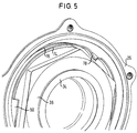
- Figure 5 is a perspective end view of the axle assembly of the present invention;
- Figure 6 is a top elevational view of the washer assembly;
- Figure 7 is a cross-sectional view of the washer assembly taken along line 7 - 7 in Figure 6;
- Figure 8 is a top elevational view of the staking washer of the washer assembly;
- Figure 9 is a cross-sectional view of the staking washer taken along line 9 - 9 in Figure 8;
- Figure 10 is an top elevational view of the retaining nut of the present invention; and
- Figure 11 is a side elevational view of the retaining nut in Figure 10.
-
- Referring to Figures 1 and 2, an
axle assembly 20 has anaxle housing 22 with aspindle 24 at each of its distal ends. Thespindle 24 defines an axis of rotation, A, about which ahub assembly 26 rotates. Thehub assembly 26 is supported by thespindle 24 and is adapted to support thewheels 28. Thehub assembly 26 also supports abrake drum 30, or a rotor for disc brakes (not shown). Abearing assembly 32 is arranged between thespindle 24 andhub assembly 26 to permit low friction rotation of thehub assembly 26 about the axis A. Thespindle 24 has a threadedend portion 34 adjacent to thebearing assembly 32 with anend nut 38 fastened to the threadedend portion 34 for retaining thebearing assembly 32 andhub assembly 26 on thespindle 24. Ahub cap 39 is secured to thehub assembly 26 to seal thebearing assembly 32 from the outside environment. - Referring now to Figure 3, a
washer assembly 42 is arranged between thebearing assembly 32 and theend nut 38. Thewasher assembly 42 secures theend nut 38 to thespindle 24 for preventing rotation of theend nut 38 about the axis A, which is described in more detail below. Thebearing assembly 32, or bearing cartridge, has a two piece cone 44 press fit onto thespindle 24 and a cup 46 press fit into aninterior surface 47 of thehub assembly 26.Roller bearings 48 are arranged radially between the cone 44 and cup 46 and are located relative to one another by acage 50.Seals 52 are arranged between the cone 44 and cup 46 at the outer ends of thebearing assembly 32 to prevent debris from penetrating thebearing assembly 32. - The
hub assembly 32 has agroove 54 on theinterior surface 47 adjacent to the cup 46. A C-shaped retaining clip 56, best shown in Figure 4, is seated in thegroove 54 to retain thebearing assembly 32 in thehub assembly 26 and prevent movement of thebearing assembly 32 along the axis A. The retainingclip 56, which has a circular cross-section, is larger than thegroove 54 so that theretaining clip 56 must be compressed to insert theclip 56 into thegroove 54. - Referring now to Figure 5 in conjunction with Figure 3, the
end nut 38 is prevented from loosening by rotating about the axis A. To this end, thewasher assembly 42 is secured to thespindle 24 and theend nut 38. Thewasher assembly 42 includes a locatingwasher 62 and astaking washer 64 that are secured to one another. The locatingwasher 62 engages agroove 60 in thespindle 24 that is generally parallel with the axis A, and thestaking washer 64 is deformed into engagement with theend nut 38. - Referring to Figures 6-9, the locating
washer 62 has a firstinner diameter 65 with atab 66 that extends radially inwardly from the firstinner diameter 65 and engages thegroove 60 thereby preventing thewasher assembly 42 from rotating about thespindle 24. Thestaking washer 64 includes a secondinner diameter 69 with at least oneprong 70 extending transversely from the secondinner diameter 69. The locatingwasher 62 has at least onenotch 68 that receives acorresponding prong 70 for securing the locating 62 and staking 64 washers together. Theprongs 70 may be bent outward from theinner diameter 69 to ensure that thewashers staking washer 64 has anouter diameter 72 with anarcuate flange 74 extending transversely from theouter diameter 72, best shown in Figures 8 and 9. - Referring to Figures 10 and 11, the
end nut 38 has anouter perimeter 76 adjacent to thearcuate flange 74. Theend nut 38 has at least onerecess 80. Aportion 78 of theflange 74 is deformed into engagement with therecess 80 of theend nut 38, preferably so that theportion 78 shears and theportion 78 abuts therecess 80 to ensure that theend nut 38 cannot rotate relative to thewasher assembly 42. Preferably, theend nut 38 has threerecesses 80 disposed radially about theend nut 38 with theflange 74 deformed into engagement with only one recess 80. By only deforming oneportion 78 of theflange 74, thesame washer assembly 42 to be used two more times. It can be seen that the retaining assembly of the present invention prevents theend nut 38 from rotating relative to thespindle 24 and loosening from its originally installed location. - The invention has been described in an illustrative manner, and it is to be understood that the terminology that has been used is intended to be in the nature of words of description rather than of limitation. Obviously, many modifications and variations of the present invention are possible in light of the above teachings. It is, therefore, to be understood that within the scope of the appended claims the invention may be practiced otherwise than as specifically described.
Claims (15)
- An axle assembly for supporting wheels comprising:a spindle defining an axis of rotation and having a threaded end portion;a hub assembly supported by said spindle and adapted to support the wheels;a bearing assembly adjacent to said threaded end portion and interposed between said spindle and said hub assembly for permitting low friction rotation of said hub assembly relative to said spindle about said axis;an end nut secured to said threaded end portion of said spindle for retaining said bearing assembly and said hub assembly on said spindle; anda washer interposed between said bearing assembly and said end nut wherein said washer secures said end nut to said spindle for preventing rotation of said end nut about said axis.
- The assembly as set forth in claim 1 wherein said washer comprises a washer assembly including a locating washer and a staking washer secured to one another, wherein said locating washer engages said spindle and said staking washer engages said end nut for preventing rotation of said washer assembly and said end nut about said axis.
- The assembly as set forth in claim 2 wherein said spindle includes a groove generally parallel with said axis, and said locating washer includes a first inner diameter with a tab extending radially inwardly therefrom which engages said groove.
- The assembly as set forth in claim 3 wherein said first inner diameter of said locating washer includes at least one notch, and said staking washer includes a second inner diameter with at least one prong extending transversely therefrom for engaging said at least one notch and securing said locating and staking washers together.
- The assembly as set forth in claim 4 wherein end nut includes an outer perimeter, and wherein said staking washer includes an outer diameter with an arcuate flange extending transversely therefrom adjacent to said outer perimeter, a portion of said flange engaging said end nut.
- The assembly as set forth in claim 5 wherein said end nut has at least one recess, said flange deformed into engagement with said at least one recess.
- The assembly as set forth in claim 6 wherein said at lease one recess comprises three recess, said flange deformed into engagement with one of said three recesses.
- A method for retaining a hub assembly and bearing assembly on a spindle of an axle assembly comprising the steps of:(a) installing a hub assembly and bearing assembly onto a spindle having an axis;(b) installing a washer onto the spindle adjacent to the bearing assembly, wherein the washer is rotationally fixed to the spindle relative to the axis;(c) fastening an end nut onto spindle adjacent to the washer; and(d) deforming the washer into engagement with the end nut for rotationally fixing the end nut relative to the spindle.
- The method as set forth in claim 8 wherein said washer comprises a washer assembly including a locating washer and a staking washer secured to one another, wherein said locating washer engages said spindle and said staking washer engages said end nut for preventing rotation of said washer assembly and said end nut about said axis.
- The method as set forth in claim 9 wherein said spindle includes a groove generally parallel with said axis, and said locating washer includes a first inner diameter with a tab extending radially inwardly therefrom which engages said groove.
- The method as set forth in claim 10 wherein said first inner diameter of said locating washer includes at least one notch, and said staking washer includes a second inner diameter with at least one prong extending transversely therefrom for engaging said at least one notch and securing said locating and staking washers together.
- The method as set forth in claim 11 wherein end nut includes an outer perimeter, and wherein said staking washer includes an outer diameter with an arcuate flange extending transversely therefrom adjacent to said outer perimeter, a portion of said flange engaging said end nut.
- The method as set forth in claim 12 wherein said end nut has at least one recess, said flange deformed into engagement with said at least one recess.
- The method as set forth in claim 13 wherein said portion of said flange is sheared when said flange is deformed into engagement with said at least one recess.
- The method as set forth in claim 14 wherein said at lease one recess comprises three recess, said flange deformed into engagement with one of said three recesses.
Applications Claiming Priority (2)
| Application Number | Priority Date | Filing Date | Title |
|---|---|---|---|
| US359236 | 1989-05-31 | ||
| US09/359,236 US6224167B1 (en) | 1999-07-22 | 1999-07-22 | Retaining assembly for an axle hub and bearing assembly |
Publications (2)
| Publication Number | Publication Date |
|---|---|
| EP1070603A2 true EP1070603A2 (en) | 2001-01-24 |
| EP1070603A3 EP1070603A3 (en) | 2003-08-06 |
Family
ID=23412933
Family Applications (1)
| Application Number | Title | Priority Date | Filing Date |
|---|---|---|---|
| EP00114983A Withdrawn EP1070603A3 (en) | 1999-07-22 | 2000-07-20 | Retaining assembly for an axle hub and bearing assembly |
Country Status (3)
| Country | Link |
|---|---|
| US (1) | US6224167B1 (en) |
| EP (1) | EP1070603A3 (en) |
| BR (1) | BR0003417A (en) |
Cited By (7)
| Publication number | Priority date | Publication date | Assignee | Title |
|---|---|---|---|---|
| WO2003070490A1 (en) * | 2002-02-20 | 2003-08-28 | Meritor Heavy Vehicle Systems Cameri Spa | Wheel hub assembly |
| WO2005012742A1 (en) * | 2003-08-01 | 2005-02-10 | Dana Corporation | Combination lock washer and spindle bearing assembly |
| DE102009027078A1 (en) * | 2009-06-22 | 2010-12-30 | Saf-Holland Gmbh | Wheel bearing for vehicle axles |
| FR3012997A1 (en) * | 2013-11-13 | 2015-05-15 | Renault Sa | ROLLING TRAIN WITH AXIAL ROTOR RETENTION MEMBER ON STATOR |
| KR20200047105A (en) * | 2018-10-26 | 2020-05-07 | 주식회사 일진글로벌 | Wheel bearing assembly |
| WO2021167148A1 (en) * | 2020-02-21 | 2021-08-26 | 주식회사 일진글로벌 | Wheel bearing assembly |
| CN113464569A (en) * | 2021-08-20 | 2021-10-01 | 盐城支点机械制造有限公司 | Bearing seat for four-row tapered roller bearing for new-structure rolling mill |
Families Citing this family (13)
| Publication number | Priority date | Publication date | Assignee | Title |
|---|---|---|---|---|
| US6860688B2 (en) * | 2001-06-15 | 2005-03-01 | Danley Construction Products Pty Ltd | Lockable nut system |
| US6896463B2 (en) * | 2001-10-04 | 2005-05-24 | Dexter Axle Company | Spindle nut retainer |
| US6443054B1 (en) | 2002-01-25 | 2002-09-03 | Mccarney Kevin T. | Hands free tortilla forming machine |
| JP4077371B2 (en) * | 2003-06-12 | 2008-04-16 | 本田技研工業株式会社 | Pivot shaft structure for swing arm support |
| US7182562B2 (en) * | 2003-12-04 | 2007-02-27 | Daimlerchrysler Corporation | Gear bolt retention in an automatic transmission assembly subjected to thrust and bending loading |
| US8092132B2 (en) * | 2008-12-05 | 2012-01-10 | American Axle & Manufacturing, Inc. | Fastener with anti-rotation clip |
| US7927052B1 (en) * | 2009-10-26 | 2011-04-19 | Arnold Varden | Locking axle nut |
| US20110291467A1 (en) * | 2010-06-01 | 2011-12-01 | Consolidated Metco, Inc. | Wheel hub assembly |
| US8469460B2 (en) | 2010-06-29 | 2013-06-25 | Arvinmeritor Technology, Llc | Spindle nut assembly |
| US9149046B2 (en) | 2013-09-03 | 2015-10-06 | Kevin McCarney | Tortilla press assembly |
| CN109458402A (en) * | 2018-11-30 | 2019-03-12 | 中钢集团西安重机有限公司 | A kind of running wheel mechanism of suspension type cover carriage |
| WO2021151649A1 (en) * | 2020-01-27 | 2021-08-05 | Volvo Truck Corporation | Rotational lock in inner ring of outboard bearing to avoid lock washer |
| US11946509B2 (en) * | 2020-03-05 | 2024-04-02 | Johnny F Powell, JR. | Wheel hub to axle fastening arrangement |
Family Cites Families (13)
| Publication number | Priority date | Publication date | Assignee | Title |
|---|---|---|---|---|
| US2561224A (en) * | 1946-11-15 | 1951-07-17 | Pischek | Locking arrangement for screws |
| US2622934A (en) * | 1947-07-19 | 1952-12-23 | Phelps Ross William | Hub construction for wheels |
| US2698202A (en) * | 1952-05-15 | 1954-12-28 | Burt W Weisel | Wheel mounting structure |
| FR1467821A (en) * | 1965-12-09 | 1967-02-03 | Citroen Sa Andre | Elastic wheel spindle mount |
| US3701564A (en) * | 1970-07-28 | 1972-10-31 | Willow Hill Ind Inc | Vehicle axle spindle |
| SE445762B (en) * | 1980-06-24 | 1986-07-14 | Volvo Ab | DEVICE FOR LOADING A NUT MEMBER ON AN AXEL TAPE |
| DE3232150A1 (en) * | 1982-08-30 | 1984-03-01 | Ralph 4048 Grevenbroich Müllenberg | Pair of locking washers for screw connections |
| US4812094A (en) * | 1987-09-24 | 1989-03-14 | Maclean-Fogg Company | Locking fastener assembly for threaded joint |
| US5560687A (en) * | 1994-03-01 | 1996-10-01 | Hub Nut Corporation | Controlled position axle nut and method system to preload tapered roller bearings |
| US5533849A (en) * | 1994-07-15 | 1996-07-09 | Hi-Shear Corporation | Self-locking nut for a wheel bearing |
| US5618143A (en) * | 1994-11-02 | 1997-04-08 | Warn Industries, Inc. | Spindle nut and locking device |
| US5772373A (en) * | 1994-11-02 | 1998-06-30 | Warn Industries, Inc. | Nut and locking device |
| US5967722A (en) * | 1998-04-08 | 1999-10-19 | Dana Corporation | Locking washer arrangement |
-
1999
- 1999-07-22 US US09/359,236 patent/US6224167B1/en not_active Expired - Lifetime
-
2000
- 2000-07-20 EP EP00114983A patent/EP1070603A3/en not_active Withdrawn
- 2000-07-24 BR BR0003417-7A patent/BR0003417A/en not_active IP Right Cessation
Non-Patent Citations (1)
| Title |
|---|
| None |
Cited By (12)
| Publication number | Priority date | Publication date | Assignee | Title |
|---|---|---|---|---|
| WO2003070490A1 (en) * | 2002-02-20 | 2003-08-28 | Meritor Heavy Vehicle Systems Cameri Spa | Wheel hub assembly |
| US7413261B2 (en) | 2002-02-20 | 2008-08-19 | Meritor Heavy Vehicle Systems Cameri Spa | Wheel hub assembly |
| US8382213B2 (en) | 2002-02-20 | 2013-02-26 | Meritor Heavy Vehicle Systems Cameri Spa | Wheel hub assembly |
| WO2005012742A1 (en) * | 2003-08-01 | 2005-02-10 | Dana Corporation | Combination lock washer and spindle bearing assembly |
| US6976816B2 (en) | 2003-08-01 | 2005-12-20 | Dana Corporation | Combination lock washer and spindle bearing assembly |
| DE102009027078A1 (en) * | 2009-06-22 | 2010-12-30 | Saf-Holland Gmbh | Wheel bearing for vehicle axles |
| DE102009027078B4 (en) * | 2009-06-22 | 2015-07-16 | Saf-Holland Gmbh | Wheel bearing for vehicle axles |
| FR3012997A1 (en) * | 2013-11-13 | 2015-05-15 | Renault Sa | ROLLING TRAIN WITH AXIAL ROTOR RETENTION MEMBER ON STATOR |
| KR20200047105A (en) * | 2018-10-26 | 2020-05-07 | 주식회사 일진글로벌 | Wheel bearing assembly |
| WO2021167148A1 (en) * | 2020-02-21 | 2021-08-26 | 주식회사 일진글로벌 | Wheel bearing assembly |
| CN113464569A (en) * | 2021-08-20 | 2021-10-01 | 盐城支点机械制造有限公司 | Bearing seat for four-row tapered roller bearing for new-structure rolling mill |
| CN113464569B (en) * | 2021-08-20 | 2022-05-17 | 盐城支点机械制造有限公司 | Bearing seat for four-row tapered roller bearing for new-structure steel rolling mill |
Also Published As
| Publication number | Publication date |
|---|---|
| EP1070603A3 (en) | 2003-08-06 |
| US6224167B1 (en) | 2001-05-01 |
| BR0003417A (en) | 2001-03-13 |
Similar Documents
| Publication | Publication Date | Title |
|---|---|---|
| US6224167B1 (en) | Retaining assembly for an axle hub and bearing assembly | |
| US5927867A (en) | Antifriction bearing fastening arrangement | |
| AU594918B2 (en) | Locking fastener assembly for threaded joint | |
| US6543858B1 (en) | Wheel end assembly | |
| US5494358A (en) | Package bearing | |
| EP0905394A2 (en) | Package bearing with retainer | |
| EP2392478A2 (en) | Wheel hub assembly | |
| JP2004514844A (en) | Bearings unitized for handling | |
| EP1250603B1 (en) | Wheel mounting with axle-mounted sensor | |
| JP4911333B2 (en) | Wheel mounting structure in a wheel bearing device | |
| EP3372422B1 (en) | Wheel mounting structure | |
| EP0733170A1 (en) | Bearing assembly with axial retention | |
| EP1006290A1 (en) | Wheel bearing assembly with brake rotor | |
| US20060233627A1 (en) | Seal washer | |
| US10752048B2 (en) | Wheel mounting structure | |
| US5398999A (en) | Vehicle brake assembly and method of installation | |
| WO1995013198A1 (en) | Wheel bearing arrangements | |
| US5746517A (en) | Retaining assembly for roller bearings | |
| CN109416094B (en) | Axle end assembly including wheel brake and hub unit | |
| EP0568958A1 (en) | A rolling element bearing for a vehicle wheel-support assembly | |
| JP2529545B2 (en) | Locking assembly for retaining the seal and preventing rotation | |
| JP2005059832A (en) | Wheel bearing assembly | |
| JP4134872B2 (en) | Rolling bearing device | |
| JP2005024019A (en) | Tapered roller bearing for wheel, and assembling method thereof | |
| JP2007069746A (en) | Bearing unit |
Legal Events
| Date | Code | Title | Description |
|---|---|---|---|
| PUAI | Public reference made under article 153(3) epc to a published international application that has entered the european phase |
Free format text: ORIGINAL CODE: 0009012 |
|
| AK | Designated contracting states |
Kind code of ref document: A2 Designated state(s): AT BE CH CY DE DK ES FI FR GB GR IE IT LI LU MC NL PT SE |
|
| AX | Request for extension of the european patent |
Free format text: AL;LT;LV;MK;RO;SI |
|
| PUAL | Search report despatched |
Free format text: ORIGINAL CODE: 0009013 |
|
| AK | Designated contracting states |
Designated state(s): AT BE CH CY DE DK ES FI FR GB GR IE IT LI LU MC NL PT SE |
|
| AX | Request for extension of the european patent |
Extension state: AL LT LV MK RO SI |
|
| RIC1 | Information provided on ipc code assigned before grant |
Ipc: 7F 16B 39/10 B Ipc: 7B 60B 27/00 A |
|
| 17P | Request for examination filed |
Effective date: 20031111 |
|
| AKX | Designation fees paid |
Designated state(s): DE ES FR GB IT |
|
| 17Q | First examination report despatched |
Effective date: 20041008 |
|
| GRAP | Despatch of communication of intention to grant a patent |
Free format text: ORIGINAL CODE: EPIDOSNIGR1 |
|
| STAA | Information on the status of an ep patent application or granted ep patent |
Free format text: STATUS: THE APPLICATION IS DEEMED TO BE WITHDRAWN |
|
| 18D | Application deemed to be withdrawn |
Effective date: 20071218 |