EP1070586B1 - Entwurf eines akustischen Tintenstrahldruckkopfes und Verfahren zum Betrieb mit Tintenfluss in Querrichtung - Google Patents
Entwurf eines akustischen Tintenstrahldruckkopfes und Verfahren zum Betrieb mit Tintenfluss in Querrichtung Download PDFInfo
- Publication number
- EP1070586B1 EP1070586B1 EP20000115326 EP00115326A EP1070586B1 EP 1070586 B1 EP1070586 B1 EP 1070586B1 EP 20000115326 EP20000115326 EP 20000115326 EP 00115326 A EP00115326 A EP 00115326A EP 1070586 B1 EP1070586 B1 EP 1070586B1
- Authority
- EP
- European Patent Office
- Prior art keywords
- liquid
- substrate
- array
- flow
- thermal expansion
- Prior art date
- Legal status (The legal status is an assumption and is not a legal conclusion. Google has not performed a legal analysis and makes no representation as to the accuracy of the status listed.)
- Expired - Lifetime
Links
Images



Classifications
-
- B—PERFORMING OPERATIONS; TRANSPORTING
- B41—PRINTING; LINING MACHINES; TYPEWRITERS; STAMPS
- B41J—TYPEWRITERS; SELECTIVE PRINTING MECHANISMS, i.e. MECHANISMS PRINTING OTHERWISE THAN FROM A FORME; CORRECTION OF TYPOGRAPHICAL ERRORS
- B41J2/00—Typewriters or selective printing mechanisms characterised by the printing or marking process for which they are designed
- B41J2/005—Typewriters or selective printing mechanisms characterised by the printing or marking process for which they are designed characterised by bringing liquid or particles selectively into contact with a printing material
- B41J2/01—Ink jet
- B41J2/135—Nozzles
- B41J2/14—Structure thereof only for on-demand ink jet heads
- B41J2/14008—Structure of acoustic ink jet print heads
-
- B—PERFORMING OPERATIONS; TRANSPORTING
- B41—PRINTING; LINING MACHINES; TYPEWRITERS; STAMPS
- B41J—TYPEWRITERS; SELECTIVE PRINTING MECHANISMS, i.e. MECHANISMS PRINTING OTHERWISE THAN FROM A FORME; CORRECTION OF TYPOGRAPHICAL ERRORS
- B41J2202/00—Embodiments of or processes related to ink-jet or thermal heads
- B41J2202/01—Embodiments of or processes related to ink-jet heads
- B41J2202/08—Embodiments of or processes related to ink-jet heads dealing with thermal variations, e.g. cooling
Definitions
- This invention relates generally to droplet emitters and more particularly concerns an acoustically actuated droplet emitter which is provided with a continuous, high velocity, laminar flow of liquid.
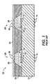
- FIG. 1 shows a cross-sectional view of a standard droplet emitter 10 for an acoustically actuated printer such as is shown in U.S. Patent No. 5,565,113 .
- the droplet emitter 10 has a base substrate 12 with transducers 16 on one surface and acoustic lenses 14 on an opposite surface. Attached to the same side of the base substrate 12 as the acoustic lenses is a top support 18 with channels, defined by sidewalls 20, which hold a flowing liquid 22. Supported by the top support 18 is a capping structure 26 with arrays 24 of apertures 30.
- the transducers 16, acoustic lenses 14, and apertures 30 are all axially aligned such that an acoustic wave produced by a single transducer 16 will be focussed by its aligned acoustic lens 14 at approximately a free surface 28 of the liquid 22 in its aligned aperture. When sufficient power is obtained, a droplet is emitted.
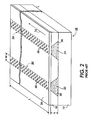
- FIG 2 shows a perspective view of the droplet emitter 10 shown in Figure 1 .
- the arrays 24 of apertures 30 can be clearly seen on the capping structure 26.
- Each array 24 has a width W and a length L where the length L of the array 24 is the larger of the two dimensions.
- Arrow Lf shows the flow direction of the flowing liquid 22 through the top support 18, which is in the direction of the length L and orthogonal to the width W of the channels formed by sidewalls 20 and is along a length L of the arrays 24. This is due to the channels formed by sidewalls 20 being constructed such that the flowing liquid 22 flows in the direction of the length L of the each array. This configuration has many advantages.
- each array is associated with a liquid having different properties. For instance, to enable a color printing application each array might be associated with a different colored ink. Furthermore, this configuration is easy to set up and attach to an ink pumping system.
- the pressure loss of the liquid 22 along the channel length L is dependent on the cross sectional area defined by sidewalls 20 and the channel length L. As the channel length L increases, the pressure loss along the flow direction increases. The portion of the pressure loss due to flow frictional losses is largely dependent upon and limited by the height h of the channel.
- This pressure loss along the flow direction can become large and results in a limited flow rate.
- the pressure loss and the limited flow rate impacts the performance of the droplet emitter 10 by limiting the droplet emission rates possible in three ways. Firstly, the pressure loss will change the level of the free surface 28 of the flowing liquid in the apertures along the length L. At the very least, different liquid levels will contribute to focussing errors of the acoustic energy focussed by the acoustic lenses 14 and result in emitted droplets not landing in their target spots.
- the slow flow rate will also mean that the flowing liquid 22 and the substrate 12 will heat up from the portion of the acoustic energy that is absorbed in the flowing liquid 22 and the substrate 12 which is not transferred to the kinetic and surface energy of the ejected drops.
- the liquid can sustain temperature increases by only a few degrees centigrade before emitted droplets show drop misplacement on the receiving media.
- the flowing liquid 22 can absorb enough energy to cause it to boil.
- the array length L, and hence the droplet emitter length must be very short to allow for faster flow rates or that the emission speed must be kept very slow to prevent the liquid from absorbing excess energy and heating up to unacceptable levels.
- a droplet emitter 10 could be designed to maintain a substantially constant pressure along the emission portion of the liquid flow path and which also has a faster flow rate for a droplet emitter array of any arbitrary length L with a minimal rise of the liquid flow temperature at high emission speeds and has sufficient liquid replenishment rates.
- US 5,087,931 describes a pressure-equalized ink transport system for acoustic ink printers.
- An ink transport system for an acoustic ink printer having an array of ejectors with associated ink bodies and free surfaces.
- the ink transport system supplies ink to the injector ink bodies constantly, yet zeros the hydrostatic gauge pressures of the free surfaces of the ink bodies to ensure uniformity of ejector performance.
- the ink transport system works with linear and two-dimensional arrays of ejectors.
- This object is achieved by providing a droplet emitter array according to claim 1.
- the droplet emitter 40 has a base substrate 42 with transducers 46 on one surface and acoustic lenses 44 on an opposite surface. Spaced from the base substrate 42 is a liquid level control plate 56. The base substrate 42 and the liquid level control plate 56 define a channel which holds a flowing liquid 52. The liquid level control plate 56 contains an array 54 of apertures 60.
- the transducers 46, acoustic lenses 44, and apertures 60 are all axially aligned such that an acoustic wave produced by a single transducer 46 will be focussed by its aligned acoustic lens 44 at approximately a free surface 58 of the liquid 52 in its aligned aperture 60. When sufficient power is obtained, a droplet is emitted.
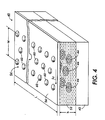
- Figure 4 shows a perspective view of the droplet emitter 40 shown in Figure 3 .
- the array 54 of apertures 60 can be clearly seen on the liquid level control plate 56.
- Arrow Lf shows the flow direction of the flowing liquid 52 between the base substrate 42 and the liquid level control plate 56. Notice that the flow direction Lf is arranged such that the flowing liquid 52 flows along the shorter width W of the array 54 instead of along the longer length L of the array 54 as in Figures 1 and 2 . In this configuration, the flow velocity of the liquid 52 is substantially independent of the distance between the sidewalls which define the channel.
- droplet emitters having a length L of 43,2 mm (1.7 inches) constructed with this configuration have sustained flow rates of 150 ml per minute with a differential meniscus position between the first and last emitter of 5 microns. These same printheads have also achieved flow rates of up to 300 ml per minute. These higher flow rates enable for instance the flowing liquid 52 to help maintain thermal uniformity of the droplet emitter 40. In particular, not only does the flowing liquid 52 itself have less opportunity to heat up due to excess heat generated during the acoustic emission process but because the flowing liquid 52 is in thermal contact with the substrate 42 the flowing liquid may also absorb excess heat generated in the substrate 42 during operation and prevent excess heating of the substrate 42 as well.
- printheads constructed as above tested at maximum emission rates with all emitters emitting at approximately 30 watts have shown a maximum instantaneous temperature differential between the first and last emitter of between approximately 2.9 degrees centigrade and 5 degrees centigrade. As can be readily appreciated, this is a large improvement over the performance of the prior art droplet emitter.
- Figure 5 shows a cross-sectional view of how the droplet emitter of Figures 3 and 4 can be assembled with fluid manifold 62 to provide the flowing liquid 52 to the droplet emitter. While unitary contruction of the fluid manifold 62 may in some circumstances be desirable, in this implementation the fluid manifold 62 is divided into two portions, an upper manifold 98 and a lower manifold 92 with a flexible seal 84 therebetween.
- the lower manifold 92 which is in direct contact with the base substrate 42 and the liquid level control plate 56, must be made from materials which have a thermal expansion coefficient relatively similar to the material the base substrate 42 is made from and preferably within a range of +/- 0.5x10 -6 per degree centigrade. This is primarily because the base substrate 42 during the course of alignment to the lower manifold 92 and liquid level control plate 56 and subsequent bonding and curing steps may go through large temperature variations of up to 250 degrees centigrade and a differential thermal expansion of the parts of more than 5 microns can damage the assembly.
- the most common material for constructing the base substrate 42 is glass which has a thermal expansion coefficient of approximately 3.9x10 -6 per degree centigrade.
- Possible materials for constructing the lower manifold 92, when the base substrate 42 is made from glass include alloy 42, Kovar, various ceramics and glass, which all have acceptable thermal expansion coefficients. However, as the length of the droplet emitter 40 increases, and hence the length of both the base substrate 42 and the liquid level control plate 56, either the allowable variation in thermal expansion coefficients, or the maximum temperature variation, or both must be correspondingly decreased.
- the upper manifold 98 is made of materials, such as inexpensive plastics, which have a different thermal expansion coefficient from glass and so are unsuitable for the lower manifold 92.
- the flexible seal 84 allows for a fluid seal between the upper manifold 98 and the lower manifold 92 while at the same time providing some give between the parts as they either expand or contract due to their different thermal expansion coefficients.
- the lower manifold 92 has a liquid level control gap protrusion 94.
- the liquid level control plate 56 is attached a liquid level control gap protrusion 94.
- the liquid level control gap protrusion 94 is used to achieve a precise spacing between the base substrate 42 and the liquid level control plate 56 when the parts are assembled into the droplet emitter 40 and attached to the lower manifold 92.
- the assembly of the droplet emitter 40 and attachment to the fluid manifold 62 creates a liquid sheet flow chamber 90 starting at the manifold inlet 86, proceeding through the gap between the base substrate 42 and the liquid level control plate 56 and ending at the manifold outlet 88.
- Both the manifold inlet 86 and the manifold outlet 88 have a sheet flow partition 64 which creates and maintains a sheet flow of the liquid flowing through the liquid sheet flow chamber 90.
- the liquid sheet flow chamber 90 has no physical or structural obstructions in the path of the flow, particularly in the portion of the sheet flow chamber 90 between the base substrate 42 and the liquid level control plate 56. This is the preferred embodiment as it ensures a uniform flow velocity for all the emitters across the entire length of the array. Furthermore, this decreases the possibility of trapped air-bubbles created during filling of the printhead or by perturbations in the liquid flow 52 and allows for the rapid removal of air bubbles that may get introduced into the system. However, it should be noted that as the length L of the droplet emitter gets larger, it may be desirable to provide additional support to the liquid level control plate 56.
- Such liquid level control plate supports 48 may be placed within the liquid flow chamber 90 provided that have a minimal footprint and are placed a minimal distance of at least five times the channel height h from both the ends of the liquid flow channel 90 and each other as shown in Figure 6 . Additionally, the supports must also be spaced at least a distance of five times the channel height h from the apertures 60. Note that the liquid level control plate supports 48 are placed in the flow direction, effectively creating several large flow chambers 50 between the liquid level control plate supports 48 in the portion of the liquid sheet flow chamber 90 where they reside.
- a bridge plate 82 An additional part assembled with the lower manifold 92 and the droplet emitter stack 40 is a bridge plate 82.
- the bridge plate 82 is used to mount a flex cable 100.
- the flex cable 100 is used to provide connections for discrete circuit components 76 which are mounted on the flex cable 100 and are used to generate and control the focussed acoustic wave.
- Bond wires 96 provide electrical connections between the flex cable 100 and circuit chips 80 mounted on the base substrate 42. Control circuitry for the droplet emitter has described for instance in U.S. Patent No. 5,786,722 by Buhler et al .
- Figure 7 shows a perspective view of the cross section of the droplet emitter shown in Figure 5 with additional thermally conductive components.
- a heat conductive backplane is inserted in the gap between the flex cable 100 and the manifold 62.
- a thermally conductive connection 74 is made between the heat conductive back plane 72 and the upper manifold 98. The thermal conduction between the heat conductive backplane 72 and the manifold 62 allows heat generated by the circuit chips 80 to be transferred to the flowing liquid 52 via the manifold 62.
- the assembly is arranged such that the excess heat is transferred to the flowing liquid 52 on the exit portion of the device or after the flowing liquid 52 has passed through most of the liquid sheet flow chamber 90 and is ready to exit the manifold 62 through the manifold outlet tube 68. This allows excess heat to be carried away from the droplet emitter 40 and helps to maintain thermal uniformity within the droplet emitter 40.
- FIG. 7 Another feature shown in Figure 7 is spring clip 78.
- the spring clip 78 is used to secure the entire assembly but allows for some movement of upper manifold 98 relative to the lower manifold 92 due to the different thermal expansion coefficients of the upper manifold 98 and the lower manifold 92.
- the upper manifold 98 could be attached to the lower manifold 92 with an elastomer glue joint.
- An elastomer glue joint would fixedly attach the upper manifold 98 to the lower manifold 92 while also allowing for some movement of the upper manifold 98 relative to the lower manifold 92 due to the different thermal expansion coefficients.
- the two flexible seals 84 in the embodiment shown in Figure 7 are two elongated o-rings.
- the compliance or stiffness of this type of o-ring seal is fairly uniform along the length of the o-ring except for the ends of the o-ring. This type of o-ring is much stiffer at the ends than along the rest of the length of the o-ring.
- Figures 8 and 9 show exploded views of the upper manifold 98 and the lower manifold 92 respectively.
- one method to make the upper manifold 98 is to divide the upper manifold into easily manufacturable components which can then be assembled into the upper manifold.
- the upper manifold is divided into an upper portion 98a and a lower portion 98b which are then assembled with a pair of baffles 102 which is inserted therebetween.
- the baffles 102 are used to aide in the conversion of the liquid flow into the upper manifold 98 in a sheet flow.
- the manifold inlet and outlet tubes 66, 68 can then be inserted into the upper portion 98a to complete assembly of the upper manifold 98.
- the lower manifold 92 can be assembled from a stack of parts in a similar manner along with the flex cable 72, base substrate 42, and the liquid level control plate 56.
- the lower manifold 92 is manufactured in four sheet-like portions 92a, 92b, 92c, and 92d. This allows for easy manufacture of the lower manifold 92 because each portion can be easily and accurately stamped, chemically etched or laser cut out of a sheet material such as readily available sheet metal stock.
- the liquid sheet flow chamber is defined by the patterns removed out of each portion 92a, 92b, 92c, 92d when the portions are stacked and assembled together with the base substrate 42, and the liquid level control plate 56.
Landscapes
- Particle Formation And Scattering Control In Inkjet Printers (AREA)
- Ink Jet (AREA)
Claims (8)
- Eine Tropfenemitteranordnung (40), umfassend:a) ein erstes Substrat (42), das einen Wärmeausdehnungskoeffizienten aufweist und angeordnet und aufgebaut ist und eine Einrichtung darauf aufweist, um eine Anordnung von fokussierten akustischen Wellen bereitzustellen;b) ein zweites Substrat (56), das von dem ersten Substrat (42) beabstandet ist, wobei das zweite Substrat eine Anordnung (54) von Öffnungen (60) aufweist, wobei die Anordnung von Öffnungen (60) eine Länge und eine Breite aufweist, wobei die Länge größer als die Breite ist, wobei das zweite Substrat in Bezug auf das erste Substrat derart angeordnet ist, dass jede Öffnung (60) fokussierte akustische Wellen von dem ersten Substrat empfangen kann; undc) eine Flüssigkeitsströmungskammer (90), die mindestens teilweise zwischen dem ersten und dem zweiten Substrat angeordnet ist, wobei die Flüssigkeitsströmungskammer (90) einen Einlass (86) und einen Auslass (88) aufweist und so aufgebaut und angeordnet ist, dass diese eine Strömung einer Flüssigkeit (52) derart aufnimmt, dass eine freie Oberfläche (58) der Flüssigkeit durch jede der Öffnungen (60) in dem zweiten Substrat (56) ausgebildet wird, und die fokussierten akustischen Wellen, die durch jede Öffnung empfangen werden, im Wesentlichen an der freien Oberfläche der Flüssigkeit, die in der Öffnung ausgebildet wird, fokussiert werden, wobei der Einlass (86) und der Auslass (88) auf gegenüberliegenden Seiten der Flüssigkeitsströmungskammer (90) in Bezug auf die Breitenrichtung der Anordnung (54) der Öffnungen (60) angeordnet sind, wodurch bewirkt wird, dass die Strömung der Flüssigkeit durch den Einlass (86) einströmt und durch den Auslass ausströmt und mindestens ein Teil der Strömung der Flüssigkeit im Wesentlichen in derselben Richtung wie die Breite der Anordnung der Öffnungen (60) fließt;dadurch gekennzeichnet, dass
die Flüssigkeitsströmungskammer (90) mindestens teilweise zwischen dem ersten und dem zweiten Substrat derart angeordnet ist, dass keine körperlichen oder strukturellen Hindernisse in dem Abschnitt der Flüssigkeitsströmungskammer (90) zwischen dem ersten Substrat (42) und dem zweiten Substrat (56) vorhanden sind; und
der Einlass (86) und der Auslass (88) jeweils eine Blende (102) umfassen, wobei jede Blende sich in der Längenrichtung im Wesentlichen über die Länge der Anordnung der Öffnungen (60) erstreckt, um die Umwandlung der Flüssigkeitsströmung in eine blattartige laminare Strömung in der Flüssigkeitsströmungskammer (90) zu unterstützen. - Die Tropfenemitteranordnung gemäß Anspruch 1, weiterhin umfassend eine Schaltung zur Erzeugung und Steuerung der fokussierten akustischen Wellen, wobei die genannte Schaltung thermisch mit der Flüssigkeitsströmungskammer (90) zur Übertragung von Wärme auf die Strömung der Flüssigkeit, bevor diese die Flüssigkeitsströmungskammer (90) verlässt, verbunden ist.
- Die Tropfenemitteranordnung gemäß Anspruch 2, wobei die genannte Schaltung thermisch mit dem Auslass (88) der Flüssigkeitsströmungskammer (90) zur Übertragung von Wärme auf die Strömung der Flüssigkeit, nachdem die Strömung der Flüssigkeit die Anordnung der Öffnungen (54) durchlaufen hat, aber bevor diese die Flüssigkeitsströmungskammer (90) verlässt, verbunden ist.
- Die Tropfenemitteranordnung gemäß Anspruch 1, wobei das erste Substrat (42) weiterhin umfasst:a) eine Anordnung von Wandlern (46) zur Erzeugung von akustischen Wellen, undb) eine Anordnung von Fokussierungseinrichtungen (44), die so angeordnet sind, dass diese die erzeugten akustischen Wellen empfangen und die empfangenen akustischen Wellen im Wesentlichen an der freien Oberfläche der Flüssigkeit fokussieren, die in den Öffnungen (60) ausgebildet wird.
- Die Tropfenemittereinrichtung gemäß Anspruch 1, weiterhin umfassend eine Fluidverzweigung (62), die einen Einlass, einen Auslass, und einen thermischen Ausdehnungskoeffizienten umfasst und so aufgebaut und angeordnet ist, dass dieselbe die Strömung der Flüssigkeit in dem Einlass aufnimmt und eine laminare Strömung der Flüssigkeit zu der genannten Flüssigkeitsströmungskammer durch den Auslass bereitstellt.
- Die Tropfenemitteranordnung gemäß Anspruch 5, wobei mindestens ein Abschnitt der Fluidverzweigung (62) aus einem Material hergestellt ist, das einen thermischen Ausdehnungskoeffizienten innerhalb von +/- 0,5x10⁻⁶ pro Grad Celsius des thermischen Ausdehnungskoeffizienten des ersten Substrats (42) aufweist.
- Die Tropfenemitteranordnung gemäß Anspruch 6, wobei mindestens ein Abschnitt der Fluidverzweigung (62) aus einem Material hergestellt ist, das einen thermischen Ausdehnungskoeffizienten aufweist, der im Wesentlichen derselbe ist wie der thermische Ausdehnungskoeffizient des ersten Substrats (42).
- Die Tropfenemitteranordnung gemäß Anspruch 5, wobei ein erster Abschnitt der Fluidverzweigung (62) aus einem Material hergestellt ist, das einen thermischen Ausdehnungskoeffizienten innerhalb von +/- 0,5x10⁻⁶ pro Grad Celsius des thermischen Ausdehnungskoeffizienten des ersten Substrats (42) aufweist, und ein zweiter Abschnitt der Fluidverzweigung (62) aus einem Material hergestellt ist, das einen thermischen Ausdehnungskoeffizienten aufweist, der im Wesentlichen unterschiedlich ist von dem thermischen Ausdehnungskoeffizienten des ersten Substrats (42) und weiterhin eine fluidische Dichtung zwischen den zwei Abschnitten umfasst.
Applications Claiming Priority (4)
| Application Number | Priority Date | Filing Date | Title |
|---|---|---|---|
| US359520 | 1999-07-23 | ||
| US361035 | 1999-07-23 | ||
| US09/359,520 US6283580B1 (en) | 1999-07-23 | 1999-07-23 | Method of operation of an acoustic ink jet droplet emitter utilizing high liquid flow rates |
| US09/361,035 US6199970B1 (en) | 1999-07-23 | 1999-07-23 | Acoustic ink jet printhead design and method of operation utilizing ink cross-flow |
Publications (3)
| Publication Number | Publication Date |
|---|---|
| EP1070586A2 EP1070586A2 (de) | 2001-01-24 |
| EP1070586A3 EP1070586A3 (de) | 2001-03-14 |
| EP1070586B1 true EP1070586B1 (de) | 2008-09-24 |
Family
ID=27000529
Family Applications (1)
| Application Number | Title | Priority Date | Filing Date |
|---|---|---|---|
| EP20000115326 Expired - Lifetime EP1070586B1 (de) | 1999-07-23 | 2000-07-14 | Entwurf eines akustischen Tintenstrahldruckkopfes und Verfahren zum Betrieb mit Tintenfluss in Querrichtung |
Country Status (5)
| Country | Link |
|---|---|
| EP (1) | EP1070586B1 (de) |
| JP (1) | JP4467725B2 (de) |
| BR (1) | BR0003104A (de) |
| CA (1) | CA2313710C (de) |
| DE (1) | DE60040318D1 (de) |
Families Citing this family (2)
| Publication number | Priority date | Publication date | Assignee | Title |
|---|---|---|---|---|
| US6484975B1 (en) * | 1999-10-28 | 2002-11-26 | Xerox Corporation | Method and apparatus to achieve uniform ink temperatures in printheads |
| CN114692334A (zh) * | 2022-03-31 | 2022-07-01 | 西安交通大学 | 一种液滴式辐射散热器中液滴层蒸发损失速率计算方法 |
Family Cites Families (7)
| Publication number | Priority date | Publication date | Assignee | Title |
|---|---|---|---|---|
| US5087931A (en) * | 1990-05-15 | 1992-02-11 | Xerox Corporation | Pressure-equalized ink transport system for acoustic ink printers |
| US5389956A (en) | 1992-08-18 | 1995-02-14 | Xerox Corporation | Techniques for improving droplet uniformity in acoustic ink printing |
| US5565113A (en) | 1994-05-18 | 1996-10-15 | Xerox Corporation | Lithographically defined ejection units |
| US5786722A (en) | 1996-11-12 | 1998-07-28 | Xerox Corporation | Integrated RF switching cell built in CMOS technology and utilizing a high voltage integrated circuit diode with a charge injecting node |
| EP0931650B1 (de) * | 1997-06-17 | 2010-04-21 | Seiko Epson Corporation | Tintenstrahlaufzeichnungskopf |
| EP1013432A3 (de) * | 1998-12-14 | 2000-08-30 | SCITEX DIGITAL PRINTING, Inc. | Kühlung von Hochspannungstreiberchips |
| US6134291A (en) * | 1999-07-23 | 2000-10-17 | Xerox Corporation | Acoustic ink jet printhead design and method of operation utilizing flowing coolant and an emission fluid |
-
2000
- 2000-07-11 CA CA 2313710 patent/CA2313710C/en not_active Expired - Fee Related
- 2000-07-14 DE DE60040318T patent/DE60040318D1/de not_active Expired - Lifetime
- 2000-07-14 EP EP20000115326 patent/EP1070586B1/de not_active Expired - Lifetime
- 2000-07-14 JP JP2000214071A patent/JP4467725B2/ja not_active Expired - Fee Related
- 2000-07-24 BR BR0003104A patent/BR0003104A/pt active Search and Examination
Also Published As
| Publication number | Publication date |
|---|---|
| EP1070586A2 (de) | 2001-01-24 |
| JP4467725B2 (ja) | 2010-05-26 |
| JP2001038901A (ja) | 2001-02-13 |
| EP1070586A3 (de) | 2001-03-14 |
| CA2313710A1 (en) | 2001-01-23 |
| CA2313710C (en) | 2004-02-17 |
| DE60040318D1 (de) | 2008-11-06 |
| BR0003104A (pt) | 2001-03-13 |
Similar Documents
| Publication | Publication Date | Title |
|---|---|---|
| US6134291A (en) | Acoustic ink jet printhead design and method of operation utilizing flowing coolant and an emission fluid | |
| EP0518380B1 (de) | Auf Anforderung arbeitender Tintenstrahldruckkopf | |
| JP3776317B2 (ja) | オンデマンド滴下インクジェット印刷装置及びインクジェット印刷方法 | |
| KR100771090B1 (ko) | 액적 증착장치 | |
| HK1006440B (en) | On-demand type ink jet print head | |
| KR20140143386A (ko) | 프린트 헤드 보강법 | |
| EP1228875B1 (de) | Verfahren zum akustischen Tintendruck mit Doppelschichtkonfiguration des Druckkopfs | |
| US6154236A (en) | Acoustic ink jet printhead design and method of operation utilizing flowing coolant and an emission fluid | |
| US6199970B1 (en) | Acoustic ink jet printhead design and method of operation utilizing ink cross-flow | |
| US6283580B1 (en) | Method of operation of an acoustic ink jet droplet emitter utilizing high liquid flow rates | |
| EP1070586B1 (de) | Entwurf eines akustischen Tintenstrahldruckkopfes und Verfahren zum Betrieb mit Tintenfluss in Querrichtung | |
| EP0710182A1 (de) | Tintenstrahlspritzdüsen | |
| US6715865B2 (en) | Liquid jet recording head packing method, liquid jet recording head and liquid jet recording apparatus | |
| CA2313712C (en) | An acoustic ink jet printhead design and method of operation utilizing flowing coolant and an emission fluid | |
| JP2008530316A (ja) | 基板を接合する方法 | |
| MXPA00007174A (es) | Diseño de cabeza de impresion de chorro de tinta acustica y metodo de operacion que utiliza flujo transversal de tinta | |
| JP3125536B2 (ja) | インクジェットヘッド | |
| JP3257140B2 (ja) | インクジェット記録装置 | |
| JP2000052553A (ja) | インクジェット式記録ヘッド | |
| JP3255788B2 (ja) | インクジェット記録ヘッドおよびインクジェット記録ヘッドの製造方法 | |
| MXPA00007172A (en) | Acoustic ink jet printhead design and method of operation utilizing flowing coolant and an emission fluid | |
| JP3182915B2 (ja) | インクジェット記録ヘッド | |
| JP2801424B2 (ja) | インクジェット記録装置および該装置における吐出回復方法 | |
| JPH01288454A (ja) | インクジェット記録ヘッドの製造方法 | |
| JPH10119276A (ja) | インクジェット記録ヘッド |
Legal Events
| Date | Code | Title | Description |
|---|---|---|---|
| PUAI | Public reference made under article 153(3) epc to a published international application that has entered the european phase |
Free format text: ORIGINAL CODE: 0009012 |
|
| AK | Designated contracting states |
Kind code of ref document: A2 Designated state(s): DE FR GB |
|
| AX | Request for extension of the european patent |
Free format text: AL;LT;LV;MK;RO;SI |
|
| PUAL | Search report despatched |
Free format text: ORIGINAL CODE: 0009013 |
|
| AK | Designated contracting states |
Kind code of ref document: A3 Designated state(s): AT BE CH CY DE DK ES FI FR GB GR IE IT LI LU MC NL PT SE |
|
| AX | Request for extension of the european patent |
Free format text: AL;LT;LV;MK;RO;SI |
|
| 17P | Request for examination filed |
Effective date: 20010914 |
|
| AKX | Designation fees paid |
Free format text: DE FR GB |
|
| 17Q | First examination report despatched |
Effective date: 20050117 |
|
| 17Q | First examination report despatched |
Effective date: 20050117 |
|
| 17Q | First examination report despatched |
Effective date: 20050117 |
|
| GRAP | Despatch of communication of intention to grant a patent |
Free format text: ORIGINAL CODE: EPIDOSNIGR1 |
|
| GRAS | Grant fee paid |
Free format text: ORIGINAL CODE: EPIDOSNIGR3 |
|
| GRAA | (expected) grant |
Free format text: ORIGINAL CODE: 0009210 |
|
| AK | Designated contracting states |
Kind code of ref document: B1 Designated state(s): DE FR GB |
|
| REG | Reference to a national code |
Ref country code: GB Ref legal event code: FG4D |
|
| REF | Corresponds to: |
Ref document number: 60040318 Country of ref document: DE Date of ref document: 20081106 Kind code of ref document: P |
|
| PLBE | No opposition filed within time limit |
Free format text: ORIGINAL CODE: 0009261 |
|
| STAA | Information on the status of an ep patent application or granted ep patent |
Free format text: STATUS: NO OPPOSITION FILED WITHIN TIME LIMIT |
|
| 26N | No opposition filed |
Effective date: 20090625 |
|
| REG | Reference to a national code |
Ref country code: FR Ref legal event code: PLFP Year of fee payment: 17 |
|
| REG | Reference to a national code |
Ref country code: FR Ref legal event code: PLFP Year of fee payment: 18 |
|
| PGFP | Annual fee paid to national office [announced via postgrant information from national office to epo] |
Ref country code: GB Payment date: 20170620 Year of fee payment: 18 Ref country code: FR Payment date: 20170621 Year of fee payment: 18 |
|
| PGFP | Annual fee paid to national office [announced via postgrant information from national office to epo] |
Ref country code: DE Payment date: 20170620 Year of fee payment: 18 |
|
| REG | Reference to a national code |
Ref country code: DE Ref legal event code: R119 Ref document number: 60040318 Country of ref document: DE |
|
| GBPC | Gb: european patent ceased through non-payment of renewal fee |
Effective date: 20180714 |
|
| PG25 | Lapsed in a contracting state [announced via postgrant information from national office to epo] |
Ref country code: DE Free format text: LAPSE BECAUSE OF NON-PAYMENT OF DUE FEES Effective date: 20190201 Ref country code: GB Free format text: LAPSE BECAUSE OF NON-PAYMENT OF DUE FEES Effective date: 20180714 Ref country code: FR Free format text: LAPSE BECAUSE OF NON-PAYMENT OF DUE FEES Effective date: 20180731 |