EP1070248B1 - Ionenmobilitätsspektrometer - Google Patents
Ionenmobilitätsspektrometer Download PDFInfo
- Publication number
- EP1070248B1 EP1070248B1 EP99924746A EP99924746A EP1070248B1 EP 1070248 B1 EP1070248 B1 EP 1070248B1 EP 99924746 A EP99924746 A EP 99924746A EP 99924746 A EP99924746 A EP 99924746A EP 1070248 B1 EP1070248 B1 EP 1070248B1
- Authority
- EP
- European Patent Office
- Prior art keywords
- ion
- drift
- mobility spectrometer
- conductor
- region
- Prior art date
- Legal status (The legal status is an assumption and is not a legal conclusion. Google has not performed a legal analysis and makes no representation as to the accuracy of the status listed.)
- Expired - Lifetime
Links
- 150000002500 ions Chemical class 0.000 claims description 53
- 239000004020 conductor Substances 0.000 claims description 35
- 239000000203 mixture Substances 0.000 claims description 7
- 125000006850 spacer group Chemical group 0.000 claims description 5
- 230000000903 blocking effect Effects 0.000 claims description 2
- 238000005036 potential barrier Methods 0.000 claims description 2
- 239000000126 substance Substances 0.000 claims description 2
- 238000005516 engineering process Methods 0.000 description 3
- 238000004519 manufacturing process Methods 0.000 description 3
- 239000004065 semiconductor Substances 0.000 description 3
- 239000000463 material Substances 0.000 description 2
- 239000000523 sample Substances 0.000 description 2
- 230000015572 biosynthetic process Effects 0.000 description 1
- 239000000919 ceramic Substances 0.000 description 1
- 238000010276 construction Methods 0.000 description 1
- 230000000694 effects Effects 0.000 description 1
- 230000005684 electric field Effects 0.000 description 1
- 239000011521 glass Substances 0.000 description 1
- 238000010438 heat treatment Methods 0.000 description 1
- 238000000034 method Methods 0.000 description 1
- 231100000572 poisoning Toxicity 0.000 description 1
- 230000000607 poisoning effect Effects 0.000 description 1
- 230000002285 radioactive effect Effects 0.000 description 1
- 238000007493 shaping process Methods 0.000 description 1
Images
Classifications
-
- G—PHYSICS
- G01—MEASURING; TESTING
- G01N—INVESTIGATING OR ANALYSING MATERIALS BY DETERMINING THEIR CHEMICAL OR PHYSICAL PROPERTIES
- G01N27/00—Investigating or analysing materials by the use of electric, electrochemical, or magnetic means
- G01N27/62—Investigating or analysing materials by the use of electric, electrochemical, or magnetic means by investigating the ionisation of gases, e.g. aerosols; by investigating electric discharges, e.g. emission of cathode
- G01N27/622—Ion mobility spectrometry
Definitions
- the invention relates to ion mobility spectrometers (IMS) having an ionization region for ionizing a substance mixture to be analyzed and forming a gaseous ion mixture, at least one ion gate adjacent to the ionization region, which is electrically switchable between a blocking and an on-state, a drift region adjacent to the at least one ion gate with an electrical drift field, wherein the drift field is generated by two conductor structures (4) arranged along the drift region, and an ion collector which is connected to an electronic system for detecting incident ions and / or electrons, wherein the ionization and drift regions are divided by two opposite wall elements (1, 2), which are interconnected via at least one spacer (3) is formed, and wherein the wall elements (1, 2) have two mutually parallel wall surfaces, between which the ion mixture flows.
- IMS ion mobility spectrometers
- the WO-A-9808087 describes an ion mobility spectrometer in which the ionization region, the ion gate, the drift region with a series of electrodes, and the ion collector are housed in a hermetically sealed package.
- the housing has two opposite parallel wall elements, which are held by further, perpendicular thereto arranged wall elements at a distance.
- the arranged perpendicular to the drift direction, however, electrodes have a certain height due to the design and thus prevent an even more compact design of the ion mobility spectrometer.
- the ion gate, the drift chamber and the ion collector is constructed of sections which can be cut out of common semiconductor material.
- the ion gate is still formed as a perpendicular to the drift direction grid, which still needs to be made comparatively expensive in semiconductor technology.
- the connection of ionization and drift chamber via the ion gate is associated with considerable mechanical manufacturing effort.
- the newly designed IMS is based on the insight that the previous three-dimensional gas conduction in the ionization and drift region can be reduced to an essentially two-dimensional design.
- a sufficiently small distance between two parallel gas-limiting wall surfaces not even a lateral closure is necessary, so that one or more simple spacers are sufficient for the connection of the wall elements, against which the wall elements are pressed by means of clips and the like.
- Due to the planar arrangement it is also possible to realize the ion gate by planar conductor structures on the wall elements, which means a very significant reduction in manufacturing costs, especially since no separate chambers for lonisations realise and the drift distance are more necessary.
- the ion collector can be produced, which means an additional simplification.
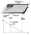
- the IMS shown in the upper half of the figure essentially has two plane-parallel plates 1 and 2 of z.
- the distance d is set by not shown spacers, which are clamped in the form of blocks or strips between the plates 1 and 2.
- the plates form, optionally taking into account the edge-limiting spacers or contact elements 3 described below, a gas-conducting channel of width b, which is at least twice the distance d, advantageously 5 to 10 times thereof.
- the plates 1 and 2 point to their respective Inside conductor structures 4, which among other things serve to generate an electric field E in the longitudinal direction (x-direction) in the interior space between the two plates 1 and 2.
- This conductor structure consists of strip-shaped conductors perpendicular to the x-direction, which are electrically connected to each other either via a thin resistive layer, not shown, or via individual resistors.
- the conductor strips can also be alternately connected with one end to the left neighbor strip and the other end to the right neighbor strip to a continuous, meandering conductor.
- the conductor strips are shown differently thick and with different distances to represent different areas. This may be convenient, but not mandatory. In the simplest case, a constant width and a constant spacing of the conductor strips of about 200 ⁇ m is sufficient.
- the individual conductor strips are contacted via a comb-like structured conductive strip 3 on one side, so that optionally the different potentials ⁇ for generating the drift field, for controlling the ion gate and for the ion collector can be applied.
- the left part of the space enclosed by the plates serves to supply the drift gas as well as the sample material and as ionization area.
- a simple and efficient ionization can be achieved, for example, by a radioactive Ni 63 source, which is arranged either at the lateral edges or in the flow region with an extension in the x direction.
- the ion collector can also be realized by conductor layers applied to the inner walls of the plates 1 and 2.
- the ionization region, the ion gate, the drift region and the ion collector form a continuous channel, which is not disturbed in terms of flow and can be easily connected via the end faces with corresponding sources for the drift or sample gas.
- the planar design also has the advantage that on the top surfaces of the plates 1 and 2 further components can be arranged. So it is z. B. possible to apply to the top surfaces of a conductor loop 5 for an electric heater of the ionization and drift region.
- a heater has the advantage that in the ionization region, the reaction kinetics in the formation of ions can be improved; In the drift area, the heating counteracts so-called poisoning by ions accumulating on the walls.
- planar design is also that the Feld Set- and shaping, especially in the drift region is greatly facilitated.
- the straight conductor strips instead of the straight conductor strips, it is also possible to apply correspondingly curved conductor strips, so as to obtain the effects known from electron optics, e.g. to achieve a focusing of the ionic current. In this way, the drifting of ions from the possibly open side areas can be prevented.
Landscapes
- Chemical & Material Sciences (AREA)
- Physics & Mathematics (AREA)
- Life Sciences & Earth Sciences (AREA)
- Chemical Kinetics & Catalysis (AREA)
- Electrochemistry (AREA)
- Health & Medical Sciences (AREA)
- Spectroscopy & Molecular Physics (AREA)
- Analytical Chemistry (AREA)
- Biochemistry (AREA)
- General Health & Medical Sciences (AREA)
- General Physics & Mathematics (AREA)
- Immunology (AREA)
- Pathology (AREA)
- Other Investigation Or Analysis Of Materials By Electrical Means (AREA)
- Measurement Of Radiation (AREA)
Description
- Die Erfindung betrifft Ionenmobilitätsspektrometer (IMS) mit einem Ionisationsbereich zum Ionisieren eines zu analysierenden Substanzgemisches und Bildung eines gasförmigen Ionengemisches, mindestens einem an den Ionisationsbereich angrenzenden lonentor, das zwischen einem Sperr- und einem Durchlasszustand elektrisch umschaltbar ist, einem an das mindestens eine lonentor angrenzenden Driftbereich mit einem elektrischen Driftfeld, wobei das Driftfeld durch zwei entlang des Driftbereichs angeordnete Leiterstrukturen (4) erzeugt wird, und einem Ionenkollektor, welcher mit einer Elektronik zum Nachweis von auftreffenden Ionen und/oder Elektronen verbunden ist, wobei der lonisations- und der Driftbereich durch zwei gegenüberliegende Wandelemente (1, 2), die über mindestens ein Abstandsstück (3) miteinander verbundenen sind, gebildet wird und wobei die Wandelemente (1, 2) zwei parallel zueinander angeordnete Wandflächen aufweisen, zwischen denen das Ionengemisch strömt.
- Die
WO-A-9808087 - Aus der
US-A-5455417 ist ein Ionenmobilitätsspektrometer bekannt geworden, dass zur Beheizung des Driftkanals eine voluminöse Vorrichtung verwendet, die jedoch für den Einsatz bei stark miniaturisierten Ionenmobilitätsspektrometern nicht geeignet ist. - In der älteren Anmeldung
DE 196 50 612 wird ein IMS beschrieben, bei dem insbesondere das Ionentor, die Driftkammer und der Ionenkollektor aus Teilstücken aufgebaut ist, welche aus gängigem Halbleitermaterial herausgeschnitten werden können. Insbesondere das Ionentor ist dabei noch als senkrecht zur Driftrichtung stehendes Gitter ausgebildet, welches auch in Halbleitertechnik noch vergleichsweise aufwendig hergestellt werden muss. Auch die Verbindung von Ionisations- und Driftkammer über das Ionentor ist mit erheblichem mechanischen Fertigungsaufwand verbunden. - Es ist Aufgabe der vorliegenden Erfindung, ein miniaturisierbares IMS zu schaffen, welches noch einfacher als bisher aufgebaut und herstellbar ist. Die Lösung dieser Aufgabe gelingt durch ein IMS mit den Merkmalen des Patentanspruches 1.
- Das neukonzipierte IMS geht von der Erkenntnis aus, dass sich die bisherige dreidimensionale Gasführung im lonisations- und Driftbereich auf eine im wesentlichen zweidimensionale Ausführung reduzieren lässt. Bei genügend kleinem Abstand zweier paralleler, gasbegrenzender Wandflächen ist dann noch nicht einmal ein seitlicher Abschluss notwendig, so dass für die Verbindung der Wandelemente ein oder mehrere simple Abstandstücke ausreichen, gegen welche die Wandelemente über Klammern und dergleichen angepresst werden. Aufgrund der planaren Anordnung gelingt es auch, das Ionentor durch planare Leiterstrukturen auf den Wandelementen zu realisieren, was eine ganz erhebliche Verminderung des Fertigungsaufwandes bedeutet, zumal keine gesonderten Kammern für die lonisationsbildung und die Driftstrecke mehr erforderlich sind. In gleicher Weise kann auch der Ionenkollektor hergestellt sein, was eine zusätzliche Vereinfachung bedeutet.
- Aufgrund der planaren Ausführung von Wandelementen und Leiterstrukturen kann zur Kontaktierung der Leiterbahnen auf sogenannte Leitgummikontakte zurückgegriffen werden, welche aus der LCD-Technik bekannt sind und dort für eine problemlose Kontaktierung einer großen Anzahl von nebeneinanderliegenden Kontaktflächen zur Anwendung kommen.
- Die Erfindung wird im folgenden anhand des in der Figur schematisch dargestellten Ausführungsbeispieles näher beschrieben.
- Das in der oberen Hälfte der Figur dargestellte IMS weist im wesentlichen zwei planparallele Platten 1 und 2 aus z. B. Glas, Keramik oder Halbleitermaterial auf, welche im wesentlichen deckungsgleich mit einem Abstand d übereinander angeordnet sind. Der Abstand d wird durch nicht näher dargestellte Abstandsstücke, die in Form von Klötzchen oder Streifen zwischen den Platten 1 und 2 eingeklemmt sind, eingestellt. Die Platten bilden, gegebenenfalls unter Berücksichtigung der randbegrenzenden Abstandstücke oder weiter unten beschriebenen Kontaktelemente 3, einen gasführenden Kanal der Breite b, welche mindestens das doppelte des Abstandes d, vorteilhafterweise das 5- bis 10 fache davon beträgt. Die Platten 1 und 2 weisen auf ihrer jeweiligen Innenseite Leiterstrukturen 4 auf, welche u.a. zur Erzeugung eines elektrischen Feldes E in Längsrichtung (x-Richtung) im Innenraum zwischen den beiden Platten 1 und 2 dienen. Diese Leiterstruktur besteht aus streifenförmigen Leitern senkrecht zur x-Richtung, weiche entweder über eine nicht dargestellte dünne Widerstandsschicht oder über Einzelwiderstände elektrisch miteinander verbunden sind. Die Leiterstreifen können auch abwechselnd mit einem Ende mit dem linken Nachbarstreifen und mit dem anderen Ende mit dem rechten Nachbarstreifen zu einem durchgehenden, mäanderförmigen Leiter verbunden sein. In der Fig. sind zur Darstellung unterschiedlicher Bereiche die Leiterstreifen unterschiedlich dick und mit unterschiedlichen Abständen dargestellt. Dies kann zweckmäßig sein, ist jedoch nicht zwingend erforderlich. Im einfachsten Fall genügt eine konstante Breite sowie ein konstanter Abstand der Leiterstreifen von ca. 200 µm. Die einzelnen Leiterstreifen werden über einen kammartig gegliederten Leitgummistreifen 3 an einer Seite kontaktiert, so dass daran gegebenenfalls die unterschiedlichen Potentiale Φ zur Erzeugung des Driftfeldes, zur Steuerung des Ionentores sowie für den Ionenkollektor angelegt werden können.
- Der linke Teil des von den Platten eingeschlossenen Raumes dient zur Zufuhr des Driftgases sowie des Probenmaterials und als Ionisationsbereich. Eine einfache und effiziente Ionisierung kann beispielsweise durch eine radioaktive Ni 63-Quelle, welche entweder an den seitlichen Rändern oder im Strömungsbereich mit einer Erstreckung in x-Richtung angeordnet ist, erzielt werden.
- Aufgrund der planaren Anordnung ergibt sich eine wesentliche Vereinfachung für die Realisierung eines Ionentores. Hierzu werden ein Teil der Leiterstreifen in dem als Ionentor bezeichneten Bereich der Leiterstruktur 4 elektrisch von den übrigen Leiterstreifen isoliert. Während der in der unteren Hälfte der Figur dargestellte Potentialverlauf an den Leiterstreifen bei offenem Ionentor mit vorgebbarem Gradienten von links nach rechts abfällt, kann zur Schließung des Ionentores an den dafür vorgesehenen Leiterstreifen die Kontinuität des Potentialverlaufs deltaförmig unterbrochen werden, so dass die im Ionisationsbereich gebildeten Ionen die Potentialbarriere nicht passieren können.
- Ebenso wie das Ionentor, so lässt sich auch der Ionenkollektor durch auf die Innenwände der Platten 1 und 2 aufgebrachte Leiterschichten realisieren.
- Aufgrund der oben beschriebenen Bauweise bilden der Ionisationsbereich, das Ionentor, der Driftbereich und der Ionenkollektor einen durchgehenden Kanal, der strömungsmäßig nicht gestört ist und einfach über die Stirnflächen mit entsprechenden Quellen für das Drift- bzw. Probengas verbunden werden kann.
- Die planare Ausführung hat weiterhin den Vorteil, dass auf den Deckflächen der Platten 1 und 2 weitere Komponenten angeordnet werden können. So ist es z. B. möglich, auf die Deckflächen eine Leiterschleife 5 für eine elektrische Heizung des Ionisations- und Driftbereiches aufzubringen. Eine derartige Heizung hat den Vorteil, dass im Ionisationsbereich die Reaktionskinetik bei der Bildung von Ionen verbessert werden kann; im Driftbereich wirkt die Heizung sogenannten Vergiftungen durch an den Wänden anlagernde Ionen entgegen.
- Die obengenannten Bauteile und Strukturen lassen sich mittels einfacher Standardprozesse der Mikrosystemtechnologie mit großer Präzision und einer Vielzahl von Variationsmöglichkeiten herstellen. Dies ermöglicht auch eine Fertigung in großen Stückzahlen zu günstigem Preis.
- Ein wesentlicher Vorteil der planaren Ausführung besteht auch darin, dass die Feldführung- und formung, insbesondere im Driftbereich erheblich erleichtert wird. So können auf den ebenen Innenflächen der Platten 1 und 2 anstelle der geraden Leiterstreifen auch entsprechend gekrümmte Leiterstreifen aufgebracht werden, um damit die aus der Elektronenoptik bekannten Effekte, z.B. eine Fokussierung des Ionenstromes, zu erreichen. Auf diese Weise lässt sich auch das Abdriften von Ionen aus den eventuell offenen Seitenbereichen verhindern.
Claims (9)
- Ionenmobilitätsspektrometer (IMS) mit
einem Ionisationsbereich zum Ionisieren eines zu analysierenden Substanzgemisches und Bildung eines gasförmigen Ionengemisches,
mindestens einem an den Ionisationsbereich angrenzenden Ionentor, das zwischen einem Sperr- und einem Durchlasszustand elektrisch umschaltbar ist,
einem an das lonentor angrenzenden Driftbereich mit einem elektrischen Driftfeld,
einem Ionenkollektor, welcher mit einer Elektronik zum Nachweis von auftreffenden Ionen und/oder Elektronen verbunden ist,
wobei der lonisations- und der Driftbereich durch zwei gegenüberliegende Wandelemente (1, 2), die über mindestens ein Abstandsstück (3) miteinander verbundenen sind, gebildet wird, und
wobei die Wandelemente (1, 2) zwei parallel zueinander angeordnete Wandflächen aufweisen, zwischen denen das Ionengemisch strömt,
dadurch gekennzeichnet, dass das Driftfeld durch zwei diametral zur Driftstrecke auf der jeweiligen Innenseite der Wandelemente (1, 2) angeordnete planare Leiterstrukturen (4) aus streifenförmigen Leitern erzeugt wird,
dass zumindest ein lonentor und der Ionenkollektor durch separierte, elektrisch getrennt ansteuerbare Bereiche der Leiterstruktur (4) gebildet ist, und
dass das Verhältnis aus Abstand (d) der das gasförmige lonengemisch begrenzenden Wandflächen zur felderzeugenden Breite (b) der Leiterstruktur (4) senkrecht zur Driftrichtung (x) zwischen 1 / 3 und 1 / 10 beträgt. - Ionenmobilitätsspektrometer nach Anspruch 1, dadurch gekennzeichnet, dass das Verhältnis aus Abstand (d) der das gasförmige lonengemisch begrenzenden Wandflächen zur felderzeugenden Breite (b) der Leiterstruktur (4) senkrecht zur Driftrichtung (x) zwischen 1 / 5 und 1 / 10 beträgt.
- Ionenmobilitätsspektrometer nach Anspruch 1 oder 2, dadurch gekennzeichnet, dass die Leiterstruktur (4) parallel zueinander und in Driftrichtung (x) nebeneinander angeordnete Leiterstreifen aufweist.
- Ionenmobilitätsspektrometer nach Anspruch 3, dadurch gekennzeichnet, dass die Leiterstreifen an den jeweiligen Enden abwechselnd zu einem mäanderförmigen Leiter verbunden sind.
- Ionenmobilitätsspektrometer nach Anspruch 3 oder 4, dadurch gekennzeichnet, dass die Leiterstreifen gekrümmt sind.
- Ionenmobilitätsspektrometer nach einem der Ansprüche 1 bis 5, dadurch gekennzeichnet, dass zumindest ein Teil der Leiterstreifen voneinander getrennt angeordnet und mit einer Widerstandsschicht untereinander verbunden sind.
- Ionenmobilitätsspektrometer nach einem der Ansprüche 1 bis 6, dadurch gekennzeichnet, dass zumindest ein Wandelement (1, 2) im lonisations- und/oder Driftbereich eine elektrisch von der Leiterstruktur (4) isolierte Heizung (5) aufweist.
- Ionenmobilitätsspektrometer nach einem der Ansprüche 1 bis 7, dadurch gekennzeichnet, dass die Leiterstreifen der Leiterstruktur (4) an zumindest jeweils einem Ende mit einem gegliederten Leitgummikontakt (3) versehen sind.
- Ionenmobilitätsspektrometer nach einem der Ansprüche 1 bis 8, dadurch gekennzeichnet, dass sich die Leiterstruktur (4) über den lonisations- und Driftbereich erstreckt, dass Mittel zur Erzeugung eines zusätzlichen Driftfeldes in dem Ionisationsbereich vorgesehen sind und dass weiterhin Mittel zur Erzeugung einer Potentialbarriere im Bereich des lonentores vorgesehen sind.
Applications Claiming Priority (3)
| Application Number | Priority Date | Filing Date | Title |
|---|---|---|---|
| DE19815436 | 1998-04-07 | ||
| DE19815436A DE19815436B4 (de) | 1998-04-07 | 1998-04-07 | Ionenmobilitätsspektrometer |
| PCT/DE1999/000993 WO1999051979A1 (de) | 1998-04-07 | 1999-04-01 | Ionenmobilitätsspektrometer |
Publications (2)
| Publication Number | Publication Date |
|---|---|
| EP1070248A1 EP1070248A1 (de) | 2001-01-24 |
| EP1070248B1 true EP1070248B1 (de) | 2008-04-23 |
Family
ID=7863797
Family Applications (1)
| Application Number | Title | Priority Date | Filing Date |
|---|---|---|---|
| EP99924746A Expired - Lifetime EP1070248B1 (de) | 1998-04-07 | 1999-04-01 | Ionenmobilitätsspektrometer |
Country Status (5)
| Country | Link |
|---|---|
| US (1) | US6479815B1 (de) |
| EP (1) | EP1070248B1 (de) |
| CA (1) | CA2325726A1 (de) |
| DE (2) | DE19861106B4 (de) |
| WO (1) | WO1999051979A1 (de) |
Families Citing this family (18)
| Publication number | Priority date | Publication date | Assignee | Title |
|---|---|---|---|---|
| US6806463B2 (en) | 1999-07-21 | 2004-10-19 | The Charles Stark Draper Laboratory, Inc. | Micromachined field asymmetric ion mobility filter and detection system |
| US6815668B2 (en) | 1999-07-21 | 2004-11-09 | The Charles Stark Draper Laboratory, Inc. | Method and apparatus for chromatography-high field asymmetric waveform ion mobility spectrometry |
| US7098449B1 (en) | 1999-07-21 | 2006-08-29 | The Charles Stark Draper Laboratory, Inc. | Spectrometer chip assembly |
| US7005632B2 (en) * | 2002-04-12 | 2006-02-28 | Sionex Corporation | Method and apparatus for control of mobility-based ion species identification |
| US6586732B2 (en) * | 2001-02-20 | 2003-07-01 | Brigham Young University | Atmospheric pressure ionization ion mobility spectrometry |
| US7274015B2 (en) * | 2001-08-08 | 2007-09-25 | Sionex Corporation | Capacitive discharge plasma ion source |
| US7091481B2 (en) | 2001-08-08 | 2006-08-15 | Sionex Corporation | Method and apparatus for plasma generation |
| US7122794B1 (en) | 2002-02-21 | 2006-10-17 | Sionex Corporation | Systems and methods for ion mobility control |
| CA2423993C (en) * | 2003-03-28 | 2010-05-11 | Reno Debono | Method and system for establishing the cleanliness of a device |
| WO2005067582A2 (en) | 2004-01-13 | 2005-07-28 | Sionex Corporation | Methods and apparatus for enhanced sample identification based on combined analytical techniques |
| WO2006060807A1 (en) * | 2004-12-03 | 2006-06-08 | Sionex Corporation | Method and apparatus for enhanced ion based sample filtering and detection |
| WO2007014303A2 (en) | 2005-07-26 | 2007-02-01 | Sionex Corporation | Ultra compact ion mobility based analyzer system and method |
| GB0618926D0 (en) * | 2006-09-26 | 2006-11-08 | Owlstone Ltd | Ion filter |
| US9588081B2 (en) | 2007-09-25 | 2017-03-07 | Ownstone Medical Limited | Interdigitated electrode configuration for ion filter |
| DE102009048063A1 (de) | 2009-09-30 | 2011-03-31 | Eads Deutschland Gmbh | Ionisationsverfahren, Ionenerzeugungsvorrichtung sowie Verwendung derselben bei der Ionenmobilitätsspektronomie |
| DE102012016583B4 (de) | 2012-08-21 | 2015-02-12 | Airbus Defence and Space GmbH | Ionenmobilitätsspektrometer zum Erfassen von Analyten |
| GB201810273D0 (en) | 2018-06-22 | 2018-08-08 | Thermo Fisher Scient Bremen Gmbh | Structural analysis of ionised molecules |
| GB2701602A (en) | 2024-10-24 | 2026-05-06 | Thermo Fisher Scient Bremen Gmbh | An ion guide and methods of manufacturing an ion guide |
Family Cites Families (13)
| Publication number | Priority date | Publication date | Assignee | Title |
|---|---|---|---|---|
| US3596088A (en) * | 1969-12-17 | 1971-07-27 | Franklin Gno Corp | Time-of-flight mass separator having a flowing gas stream perpendicular to an ion drift field for increased resolution |
| US4855595A (en) | 1986-07-03 | 1989-08-08 | Allied-Signal Inc. | Electric field control in ion mobility spectrometry |
| IL97742A0 (en) | 1991-04-01 | 1992-06-21 | Israel Atomic Energy Comm | Spectrometer |
| DE4134212A1 (de) * | 1991-10-16 | 1993-04-22 | Leonhardt Juergen W Prof Dr | Mikroionisationssensor zum selektiven nachweis umweltschaedigender substanzen in gasgemischen und luft |
| US5420424A (en) * | 1994-04-29 | 1995-05-30 | Mine Safety Appliances Company | Ion mobility spectrometer |
| US5455417A (en) * | 1994-05-05 | 1995-10-03 | Sacristan; Emilio | Ion mobility method and device for gas analysis |
| KR0156602B1 (ko) * | 1994-07-08 | 1998-12-01 | 황해웅 | 이온이동도 분석기 |
| DE19515270C2 (de) * | 1995-04-26 | 2000-05-11 | Bruker Saxonia Analytik Gmbh | Verfahren zur Messung von Ionenmobilitätsspektren |
| DE19627621C2 (de) * | 1996-07-09 | 1998-05-20 | Bruker Saxonia Analytik Gmbh | Ionenmobilitätsspektrometer |
| GB9617409D0 (en) * | 1996-08-20 | 1996-10-02 | Graseby Dynamics Ltd | Drift tubes |
| DE19650612C2 (de) * | 1996-12-06 | 2002-06-06 | Eads Deutschland Gmbh | Ionenmobilitätsspektrometer |
| DE19730898C2 (de) * | 1997-07-18 | 1999-06-17 | Bruker Saxonia Analytik Gmbh | Verfahren zum Erstellen eines Ionenmobilitätsspektrums |
| US5965882A (en) * | 1997-10-07 | 1999-10-12 | Raytheon Company | Miniaturized ion mobility spectrometer sensor cell |
-
1998
- 1998-04-07 DE DE19861106A patent/DE19861106B4/de not_active Expired - Fee Related
-
1999
- 1999-04-01 US US09/647,991 patent/US6479815B1/en not_active Expired - Lifetime
- 1999-04-01 DE DE59914739T patent/DE59914739D1/de not_active Expired - Lifetime
- 1999-04-01 EP EP99924746A patent/EP1070248B1/de not_active Expired - Lifetime
- 1999-04-01 CA CA002325726A patent/CA2325726A1/en not_active Abandoned
- 1999-04-01 WO PCT/DE1999/000993 patent/WO1999051979A1/de not_active Ceased
Also Published As
| Publication number | Publication date |
|---|---|
| EP1070248A1 (de) | 2001-01-24 |
| WO1999051979A1 (de) | 1999-10-14 |
| DE19861106B4 (de) | 2008-01-10 |
| CA2325726A1 (en) | 1999-10-14 |
| DE19861106A1 (de) | 2000-02-03 |
| DE59914739D1 (de) | 2008-06-05 |
| US6479815B1 (en) | 2002-11-12 |
Similar Documents
| Publication | Publication Date | Title |
|---|---|---|
| EP1070248A1 (de) | Ionenmobilitätsspektrometer | |
| DE102007049350B4 (de) | APCI Ionenquelle | |
| DE2625515A1 (de) | Heizvorrichtung fuer gase oder fluessigkeiten | |
| DE69431129T2 (de) | Ionisator für Zykloiden-Massenspektrometer | |
| DE112017000366B4 (de) | Mit Ionenmobilitätstrennungsteil ausgestattete Analysevorrichtung | |
| DE102006006683B4 (de) | Driftröhre für ein Ionenmobilitätsspektrometer mit integriertem Gaskanal | |
| DE10324839B4 (de) | Massenspektrometer | |
| DE112014002706T5 (de) | Verfahren zum Erzeugen eines elektrischen Felds zum Manipulieren geladener Teilchen | |
| WO2008101669A1 (de) | Massenspektrometer | |
| DE19815436B4 (de) | Ionenmobilitätsspektrometer | |
| EP2965337B1 (de) | Plattenstapel für kühlvorrichtung in installationsgeräten | |
| DE102018113331B4 (de) | Ionenmobilitätsspektrometer | |
| EP1467597B1 (de) | Heizvorrichtung | |
| DE2527609C3 (de) | Ionenquelle | |
| DE102022106100B4 (de) | Doppelfrequenz-hochfrequenz-vorrichtung zum einschluss von ionen | |
| EP4034868B1 (de) | Ionenmobilitätsspektrometer | |
| EP3552711B1 (de) | Elektrostatische filtereinheit und lüftungsvorrichtung mit elektrostatischer filtereinheit | |
| DE19949538C2 (de) | Mikrokapillare und Verfahren zu deren Herstellung | |
| DE102022117190A1 (de) | Ionenmobilitätsspektrometer und Verfahren zur Analyse von Substanzen | |
| DE102012211594B4 (de) | Bogenförmige beheizte Ionenübertragungsoptik | |
| DE10362062B4 (de) | Massenspektrometer | |
| DE2512873C2 (de) | Einrichtung zur Förderung der Elektronenentladung für eine Gasentladungs-Anzeigevorrichtung | |
| DE102025100846A1 (de) | Ionenführungselektrodenkonfigurationen für ionentransport und -einschluss | |
| DE19750788A1 (de) | Ionisationsmeßkammer für ein Photoionisations-Meßgerät | |
| DE1414569C (de) | Ionen Vakuumpumpe |
Legal Events
| Date | Code | Title | Description |
|---|---|---|---|
| PUAI | Public reference made under article 153(3) epc to a published international application that has entered the european phase |
Free format text: ORIGINAL CODE: 0009012 |
|
| 17P | Request for examination filed |
Effective date: 20001104 |
|
| AK | Designated contracting states |
Kind code of ref document: A1 Designated state(s): CH DE FR GB LI |
|
| RAP1 | Party data changed (applicant data changed or rights of an application transferred) |
Owner name: EADS DEUTSCHLAND GMBH |
|
| 17Q | First examination report despatched |
Effective date: 20050404 |
|
| GRAP | Despatch of communication of intention to grant a patent |
Free format text: ORIGINAL CODE: EPIDOSNIGR1 |
|
| GRAS | Grant fee paid |
Free format text: ORIGINAL CODE: EPIDOSNIGR3 |
|
| GRAA | (expected) grant |
Free format text: ORIGINAL CODE: 0009210 |
|
| AK | Designated contracting states |
Kind code of ref document: B1 Designated state(s): CH DE FR GB LI |
|
| REG | Reference to a national code |
Ref country code: GB Ref legal event code: FG4D Free format text: NOT ENGLISH |
|
| REG | Reference to a national code |
Ref country code: CH Ref legal event code: EP |
|
| REF | Corresponds to: |
Ref document number: 59914739 Country of ref document: DE Date of ref document: 20080605 Kind code of ref document: P |
|
| ET | Fr: translation filed | ||
| PLBE | No opposition filed within time limit |
Free format text: ORIGINAL CODE: 0009261 |
|
| STAA | Information on the status of an ep patent application or granted ep patent |
Free format text: STATUS: NO OPPOSITION FILED WITHIN TIME LIMIT |
|
| 26N | No opposition filed |
Effective date: 20090126 |
|
| PGFP | Annual fee paid to national office [announced via postgrant information from national office to epo] |
Ref country code: GB Payment date: 20140422 Year of fee payment: 16 |
|
| PGFP | Annual fee paid to national office [announced via postgrant information from national office to epo] |
Ref country code: DE Payment date: 20140418 Year of fee payment: 16 Ref country code: CH Payment date: 20140418 Year of fee payment: 16 Ref country code: FR Payment date: 20140422 Year of fee payment: 16 |
|
| REG | Reference to a national code |
Ref country code: DE Ref legal event code: R081 Ref document number: 59914739 Country of ref document: DE Owner name: AIRBUS DEFENCE AND SPACE GMBH, DE Free format text: FORMER OWNER: EADS DEUTSCHLAND GMBH, 85521 OTTOBRUNN, DE Effective date: 20140814 |
|
| REG | Reference to a national code |
Ref country code: DE Ref legal event code: R119 Ref document number: 59914739 Country of ref document: DE |
|
| REG | Reference to a national code |
Ref country code: CH Ref legal event code: PL |
|
| GBPC | Gb: european patent ceased through non-payment of renewal fee |
Effective date: 20150401 |
|
| PG25 | Lapsed in a contracting state [announced via postgrant information from national office to epo] |
Ref country code: DE Free format text: LAPSE BECAUSE OF NON-PAYMENT OF DUE FEES Effective date: 20151103 Ref country code: CH Free format text: LAPSE BECAUSE OF NON-PAYMENT OF DUE FEES Effective date: 20150430 Ref country code: GB Free format text: LAPSE BECAUSE OF NON-PAYMENT OF DUE FEES Effective date: 20150401 Ref country code: LI Free format text: LAPSE BECAUSE OF NON-PAYMENT OF DUE FEES Effective date: 20150430 |
|
| REG | Reference to a national code |
Ref country code: FR Ref legal event code: ST Effective date: 20151231 |
|
| PG25 | Lapsed in a contracting state [announced via postgrant information from national office to epo] |
Ref country code: FR Free format text: LAPSE BECAUSE OF NON-PAYMENT OF DUE FEES Effective date: 20150430 |