EP1070172B1 - Papermaking belt providing improved drying efficiency for cellulosic fibrous structures - Google Patents
Papermaking belt providing improved drying efficiency for cellulosic fibrous structures Download PDFInfo
- Publication number
- EP1070172B1 EP1070172B1 EP99909152A EP99909152A EP1070172B1 EP 1070172 B1 EP1070172 B1 EP 1070172B1 EP 99909152 A EP99909152 A EP 99909152A EP 99909152 A EP99909152 A EP 99909152A EP 1070172 B1 EP1070172 B1 EP 1070172B1
- Authority
- EP
- European Patent Office
- Prior art keywords
- machine direction
- belt
- direction yarns
- yarns
- cross
- Prior art date
- Legal status (The legal status is an assumption and is not a legal conclusion. Google has not performed a legal analysis and makes no representation as to the accuracy of the status listed.)
- Expired - Lifetime
Links
Images


Classifications
-
- D—TEXTILES; PAPER
- D21—PAPER-MAKING; PRODUCTION OF CELLULOSE
- D21F—PAPER-MAKING MACHINES; METHODS OF PRODUCING PAPER THEREON
- D21F11/00—Processes for making continuous lengths of paper, or of cardboard, or of wet web for fibre board production, on paper-making machines
- D21F11/006—Making patterned paper
-
- Y—GENERAL TAGGING OF NEW TECHNOLOGICAL DEVELOPMENTS; GENERAL TAGGING OF CROSS-SECTIONAL TECHNOLOGIES SPANNING OVER SEVERAL SECTIONS OF THE IPC; TECHNICAL SUBJECTS COVERED BY FORMER USPC CROSS-REFERENCE ART COLLECTIONS [XRACs] AND DIGESTS
- Y10—TECHNICAL SUBJECTS COVERED BY FORMER USPC
- Y10S—TECHNICAL SUBJECTS COVERED BY FORMER USPC CROSS-REFERENCE ART COLLECTIONS [XRACs] AND DIGESTS
- Y10S162/00—Paper making and fiber liberation
- Y10S162/90—Papermaking press felts
-
- Y—GENERAL TAGGING OF NEW TECHNOLOGICAL DEVELOPMENTS; GENERAL TAGGING OF CROSS-SECTIONAL TECHNOLOGIES SPANNING OVER SEVERAL SECTIONS OF THE IPC; TECHNICAL SUBJECTS COVERED BY FORMER USPC CROSS-REFERENCE ART COLLECTIONS [XRACs] AND DIGESTS
- Y10—TECHNICAL SUBJECTS COVERED BY FORMER USPC
- Y10S—TECHNICAL SUBJECTS COVERED BY FORMER USPC CROSS-REFERENCE ART COLLECTIONS [XRACs] AND DIGESTS
- Y10S162/00—Paper making and fiber liberation
- Y10S162/902—Woven fabric for papermaking drier section
Definitions
- the present invention relates to papermaking, and more particularly to belts used in papermaking.
- Belts of the present invention can reduce energy consumption and improve the drying rate required for thermal drying of paper fibers formed on a three dimensional belt.
- Cellulosic fibrous structures such as paper towels, facial tissues, napkins and toilet tissues, are a staple of every day life.
- the large demand for and constant usage of such consumer products has created a demand for improved versions of these products and, likewise, improvement in the methods of their manufacture.
- Such cellulosic fibrous structures are manufactured by depositing an aqueous slurry from a headbox onto a Fourdrinier wire or a twin wire paper machine. Either such forming wire is an endless belt through which initial dewatering occurs and fiber rearrangement takes place. Frequently, fiber loss occurs due to fibers flowing through the forming wire along with the liquid carrier from the headbox.
- the papermaking machine transports the web to the dry end of the machine.
- a press felt compacts the web into a single region, i.e., uniform density and basis weight, cellulosic fibrous structure prior to final drying.
- the final drying is usually accomplished by a heated drum, such as a Yankee drying drum.
- micropore drying in which drying is driven primarily by capillary attraction and uniform distribution of air flow.
- Micropore drying also known as limiting-orifice through-air drying, is particularly useful for removing interstitial water from the web.
- Micropore drying typically includes two drying phases. In the first phase, capillary attraction between water and fibers in the web is overcome by vacuum-induced capillary suction which draws the water into the fine capillary network of the micropore drying surface. In the second phase, the fine capillary network of the micropore drying surface helps to uniformly distribute the air that is passed through the paper web.
- micropore drying is described in commonly assigned U.S. Patent Nos. 5,274,930, issued January 4, 1994 to Ensign et al.; and 5,625,961, issued May 6, 1997 to Ensign et al..
- Drying efficiency is an issue in all predrying processes.
- the hot air passes through the drying belt first, then through the sheet.
- Water carried by the drying belt is partially evaporated, thereby reducing sheet drying efficiency. Production rates are thus impacted by the water-carrying characteristics of the drying belt.
- through-air-drying preferably dries the web between wet transfer and "dry transfer.”
- dry transfer the web is transferred to a heated drum, such as a Yankee drying drum for final drying.
- a heated drum such as a Yankee drying drum for final drying.
- portions of the web are densified during imprinting to yield a multi-region structure. Many such multi-region structures have been widely accepted as preferred consumer products.
- a significant improvement in through-air-drying belts is the use of a resinous framework on a reinforcing structure.
- the resinous framework generally has a first surface and a second surface, and deflection conduits extending between these surfaces.
- the deflection conduits provide areas into which the fibers of the web can be deflected and rearranged.
- This arrangement allows drying belts to impart continuous patterns, or, patterns in any desired form, rather than only the discrete patterns achievable by the woven belts of the prior art. Examples of such belts and the cellulosic fibrous structures made thereby can be found in U.S. Patents 4,514,345, issued April 30, 1985 to Johnson et al.; 4,528,239, issued July 9.
- patterned resinous through-air-drying belts use a reinforcing structure, the reinforcing structure preferably being an interwoven fabric.
- the reinforcing structure preferably provides sufficient rigidity to the belt, making it durable for papermaking. Without sufficient rigidity, the life of the papermaking belt is compromised, making frequent belt changes necessary. The cost of replacement belts, as well as the cost of the accompanying down time to the papermaking machine is unacceptable for commercial papermaking operations.
- the reinforcing structure also has an important function of supporting the fibers fully deflected into the above-mentioned deflection conduits of the resinous framework, thereby enhancing web characteristics, for example, by minimizing pinholing in the web.
- Fiber support is characterized by a Fiber Support Index, or FSI, and reinforcing structures having an FSI as low as 40 have been found useful.
- FSI Fiber Support Index
- reinforcing structures having an FSI as low as 40 have been found useful.
- the Fiber Support Index is defined in Robert L. Beran, "The Evaluation and Selection of Forming Fabrics," Tappi April 1979, Vol. 62, No. 4.
- the reinforcing structure ideally has low void volume, thereby being low water carrying.
- void volume and water carrying capacity do not perfectly correlate, in general, water carrying capacity is inherently limited by the available void volume. Therefore, by minimizing the void volume of the reinforcing structure, the water carrying capacity is necessarily minimized as well.
- a new generation of patterned resinous framework and reinforcing structure through-air-drying belts addressed some of these issues.
- This generation utilized a dual layer reinforcing structure having two layers of machine direction yarns.
- a single cross-machine direction yarn system ties the two layers of machine direction yarns together.
- the dual layer reinforcing structure added rigidity and resulted in a much more durable belt, able to withstand the aforementioned environment of a typical papermaking machine.
- the belt caliper and void volume increased, causing the belt to carry much more water through the drying process, resulting in some drying inefficiencies during papermaking.
- dual layer reinforcing structures did not always provide adequate fiber support (i.e., unacceptable Fiber Support Index, as described below), resulting in additional development to minimize undesirable paper characteristics, including pinholes.
- EP 211 426 discloses a papermaking fabric which includes a first layer of warp yarns, and a second layer of warp yarns vertically spaced from the first layer, and wherein a single weft system is interwoven with the first and second warp layers in a balance weave pattern that maintains the warp yarns of the respective layers stacked. There is however no suggestion in EP 211 426 concerning a Fibre Support Index, or a N-shed pattern where N is greater than four.
- triple layer reinforcing structures were developed, the triple layer belts being essentially a two layer structure with each layer comprising machine direction yarns and cross-machine direction yarns (i.e., warps and shutes).
- the top layer i.e., web facing layer
- the top layer is a square weave.
- the use of the square weave web-facing layer provides improved fiber support, and increased belt rigidity, as compared to dual layer belts.
- the void volume is higher than dual layer belts, resulting in high water carrying through-air-drying belts. Again, the high water content during processing results in additional energy costs to dry the paper web.
- Preferred triple layer belts are disclosed in U.S. Pat. Nos. 5,496,624, issued to Stelljes et al. on March 5, 1996; and 5,500,277 issued to Trokhan et al. on March 19, 1996.
- multiple layer structures offer sufficient belt rigidity, and may offer sufficient fiber support, but they generally contain high void volumes within the belt, which result in high water carrying capacity.
- This water content adds to the overall drying requirements of the papermaking process.
- Belt-carried water decreases the efficiency of through-air-drying processes, especially micropore drying where heated air typically encounters the belt-carried water prior to drying the paper webs. A significant amount of energy is expended to remove water trapped in the interstitial void volume of the belt prior to or during drying of the paper web.
- Dual-layer structures provide sufficient rigidity, resulting in increased belt life, and indeed are currently used for commercial paper production.
- dual layer belts tend to have relatively large void volumes within the reinforcing structure, thereby carrying excess amounts of water through the drying process. The excess amount of water can contribute to the overall energy costs associated with drying by limiting drying rates.
- Triple layer, and other multiple layer configurations also exhibit high water carrying reinforcing structures.
- the prior art required a trade-off between low void volume (for low water carrying capacity) and flexural rigidity (for long belt life).
- the prior art required a tradeoff between high open area (for better through-air drying) and a fine mesh top surface weave of the reinforcing structure, (forming a monoplanar web facing surface for better fiber support).
- the present invention is a papermaking belt comprising two primary elements: a reinforcing structure and pattern layer.
- the reinforcing structure comprises a web facing first surface of interwoven first machine direction yarns and cross-machine direction yarns, the first surface having an FSI of at least about 68.
- the reinforcing structure has a machine facing second surface which comprises second machine direction yarns binding only with the cross-machine direction yarns in a N-shed pattern, where N is greater than four, wherein the second machine direction yarns bind only one of the cross-machine direction yarns per repeat.
- the pattern layer extends outwardly from the first surface, wherein the pattern layer provides a web contacting surface facing outwardly from the first surface, the pattern layer extending at least partially to the second surface.
- the belt 10 of the present invention is preferably an endless belt and may receive cellulosic fibers discharged from a headbox or carry a web of cellulosic fibers to a drying apparatus, typically a heated drum, such as a Yankee drying drum (not shown).
- a drying apparatus typically a heated drum, such as a Yankee drying drum (not shown).
- the endless belt 10 may either be executed as a forming wire, a belt for a crescent former, a press felt, a through-air-drying belt, or a limiting orifice through-air-drying belt, as needed.
- Belt 10 is preferably a patterned resinous through-air-drying belt useful for reducing dewatering energy costs in through air drying operations of papermaking.
- the belt 10 of the present invention comprises two primary elements: a reinforcing structure 12 and pattern layer 30 .
- the reinforcing structure 12 is a structure comprised of interwoven first machine direction (FMD) yarns 120 , second machine direction yarns (SMD) 220 , and cross-machine direction (CD) yarns 122 .
- First machine direction yarns 120 and cross-machine direction yarns 122 form a web facing first surface 16 .
- Second machine direction yarns 220 and cross-direction yarns 122 form a machine facing second surface 18 .
- the patterned resinous belt 10 has two opposed surfaces, a web contacting surface 40 disposed on the outwardly facing surface of the pattern layer 30 and an opposed backside surface 42 .
- the web contacting surface 40 may also be referred to as the web facing surface.
- the backside surface 42 of the belt 10 contacts the papermaking machinery during the papermaking operation, and therefore may be termed the machine facing surface of the papermaking belt.
- Papermaking machinery includes vacuum pickup shoes, vacuum boxes, various rollers, and the like.
- the pattern layer 30 is cast from photosensitive resin, as described more fully in the aforementioned patents incorporated herein by reference.
- the preferred method for applying the photosensitive resin forming the pattern layer 30 to the reinforcing structure 12 in the desired pattern is to coat the reinforcing layer with the photosensitive resin in a liquid form.
- Actinic radiation having an activating wavelength matched to the curing characteristic of the resin, illuminates the liquid photosensitive resin through a mask having transparent and opaque regions.
- the actinic radiation passes through the transparent regions and cures, i.e., solidifies, the resin therebelow into the desired pattern.
- the liquid resin shielded by the opaque regions of the mask is not cured, i.e., remains liquid, and is washed away, leaving the conduits 44 in the pattern layer 30 .
- machine direction yarns 120 of first surface 16 is generic to and inclusive of first machine direction yarns 120 of first surface 16 , second machine direction yarns 220 of second surface 18 , as well as cross-machine direction yarns 122 , which occupy portions of both the first and second surfaces.
- machine direction refers to that direction which is parallel to the principal flow of the paper web through the papermaking apparatus.
- cross-machine direction is perpendicular to the machine direction and lies within the plane of the belt 10 .
- a “knuckle” on web facing first surface 16 is the intersection of a machine direction yarn 120 or 220 , and a cross-machine direction yarn 122 .
- the “shed” is the minimum number of yarns 100 necessary to make a repeating unit in the principal direction of a yarn 100 under consideration.
- the first machine direction yarns 120 in the first surface 16 are woven with cross-machine direction yarns 122 so as to have an FSI of at least about 68, more preferably at least about 80, and most preferably at least about 95 .
- the second machine direction yarns 220 are binding with the cross-machine direction yarns 122 in an N-shed pattern, where N > 4.
- first surface 16 can be a 2-shed square weave
- machine facing surface 18 can be an 8-shed pattern.
- machine-direction yarns 220 are placed under seven and over one cross-direction yarn(s) 122 , in a repeating pattern.
- the machine direction is also referred to as the "warp”
- the second machine direction yarns 120 of the present invention are also referred to as "warp runners”
- the reinforcing structure of the present invention may also be termed a "warp runner” reinforcing structure.
- machine direction yarns 120 and 220 in a vertically stacked configuration
- the actual configuration of the reinforcing structure is not meant to be so limited.
- the machine direction yarns may be vertically stacked as shown, especially during manufacture of the reinforcing structure, but in use they may vary substantially from the positions illustrated.
- the warp runner reinforcing structure described above does exhibit decreased thickness over existing dual layer belts, as well as decreased water carrying capacity, when used alone it is not durable enough for commercial papermaking. This is because the long backside floats 20 , upon which the entire belt makes contact with papermaking machinery, are scraped directly against the machinery, such as vacuum boxes. The backside floats relatively quickly abrade and wear to the point of failure, at which time the entire belt fails. Furthermore, the long, uninterrupted backside floats decrease the number of interlocking crimp points, making the weave too "flimsy” or “sleazy” in that the fabric is easily distorted by handling or even by its own weight if not supported. Sleaziness is described as the belt's ability to undergo shear deformation when subjected to in-plane shear forces. Too high a level of sleaziness contributes to early belt failure in commercial papermaking.
- reinforcing structure 12 can be greatly improved by casting a resinous pattern layer 30 onto reinforcing structure 12 , to form the belt 10 of the present invention.
- the pattern layer 30 penetrates the reinforcing structure 12 and is cured into any desired pattern by irradiating liquid resin with actinic radiation through a binary mask having opaque sections and transparent sections.
- the cured resinous pattern layer 30 adds rigidity, and reduces sleaziness, both of which increase the durability of the belt 10 .
- Belt durability is also increased due to the protection afforded by the cast resin on the web-facing surface of the reinforcing structure.
- the resin provides a durable wear surface, giving additional abrasion resistance to the belt 10 .
- the resinous pattern of the belt 10 may further comprise conduits 44 extending from and in fluid communication with the web contacting surface 40 of the backside surface 42 of the belt 10 .
- the conduits 44 allow deflection of the cellulosic fibers normal to the plane of the belt 10 during the papermaking operation.
- the conduits 44 may be discrete, as shown, if an essentially continuous pattern layer 30 is selected.
- the pattern layer 30 can be discrete and the conduits 44 may be essentially continuous.
- Such an arrangement is easily envisioned by one skilled in the art as generally opposite that illustrated in Figure 1.
- Such an arrangement, having a discrete pattern layer 30 and an essentially continuous conduit 44 is illustrated in Figure 4 of the aforementioned U.S. Patent 4,514,345 issued to Johnson et al. and incorporated herein by reference.
- pattern layer configurations include semi-continuous patterns, such as those disclosed in U.S. Patent 5,714,041, issued to Ayers et al., and configurations producing visually discernible, large scale patterns, such as those disclosed in U.S. Patent 5,431,786 issued to Rasch et al., both patents which are hereby incorporated herein by reference.
- the belt of the present invention may also be formed having zones with different flow resistances, such as disclosed in U.S. Patent 5,503,715 issued to Trokhan et al., and hereby incorporated herein by reference.
- Other patterns and configurations may be employed in a belt of the present invention; those listed are meant to be exemplary, and not limiting. Of course, it will be recognized as well that any combination of discrete and continuous patterns may be selected as well.
- a belt of the present invention may further comprise a dewatering felt layer.
- a curable resin such as a photosensitive resin
- a substrate such as a papermaker's dewatering felt
- Patterned resinous through-air-drying belts made according to the present invention have lower caliper (thickness) than prior art belts, for equal amounts of overburden and comparable mesh counts and filament diameters in the reinforcing structure.
- "Overburden” refers to the amount of caliper increase due solely to the cured resin, that is, the distance between top plane 46 and web contacting surface 40 The decreased caliper is due to the decrease in caliper of the reinforcing structure utilized in the present invention.
- a reinforcing structure of the present invention preferably exhibits a caliper reduction of at least about 25% over patterned resinous belts utilizing a current dual-layer reinforcing structures. Of course, the caliper depends upon the diameter and mesh count of the constituent yarn filaments, as disclosed in more detail below.
- the lower caliper of belts according to the present invention contributes to a belt having low void volume, acceptable rigidity, and high FSI.
- the low void volume and low caliper also contribute to the related benefit of low water carrying capacity, thereby increasing drying efficiency and lowering energy costs.
- Belt 10 provides for reduced energy consumption in the papermaking process because it overcomes the prior art trade-off of belt life and reduced water carrying capacity. Importantly, because of its high FSI, the belt 10 also produces an aesthetically acceptable consumer product comprising a cellulosic fibrous structure. Detailed disclosure and teaching of preferred embodiments is described below.
- FIGS. 1-3 show a preferred reinforcing structure of the present invention.
- the first machine direction and cross-machine direction yarns 120, 122 are interwoven into a web facing first surface 16 .
- the first surface 16 preferably has a one-over, one-under square weave.
- the first machine direction and cross-machine direction yarns 120 and 122 comprising the first surface 16 are substantially transparent to actinic radiation.
- Yarns 120 and 122 are considered to be substantially transparent if actinic radiation can pass through the greatest cross-sectional dimension of the yarns 120 and 122 in a direction generally perpendicular to the plane of the belt 10 and still sufficiently cure photosensitive resin therebelow.
- second machine direction yarns 220 are interwoven into a machine facing second surface 18, binding with the cross-machine direction yarns 122 in an N-shed pattern, wherein N > 4.
- the second machine direction yarns 220 are binding with one cross-machine direction yarn 122 per repeat, thereby forming uninterrupted backside floats between repeats.
- All the constituent yarns may be of equal diameters, but in a preferred embodiment, cross-machine direction yarns 122 are preferably of larger diameter than the first machine direction yarns 120 and second machine direction yarns 220 (if yarns having a round cross section are utilized).
- machine direction yarns 120 and 220 may be 0.15 - 0.22 mm in diameter and the cross-machine direction yarns 122 may be 0.17 - 0.28 mm in diameter, respectively.
- Yarns 100 are preferably made of a polymeric material.
- first machine direction yarns 120 and cross direction yarns 122 are made of polyester, for example, poly(ethylene terephthalate) (PET), and are substantially transparent to actinic radiation which is used to cure the pattern layer 30 .
- Yarns 120, 122 are considered to be substantially transparent if actinic radiation can pass through the greatest cross-sectional dimension of the yarns 120, 122 in a direction generally perpendicular to the plane of the belt 10 and still sufficiently cure photosensitive resin therebelow.
- the reinforcing structure of the present invention has relatively low void volume, thereby being low water carrying.
- void volume and water carrying capacity do not perfectly correlate, in general, water carrying capacity is inherently limited by the available void volume. Therefore, by minimizing the void volume of the reinforcing structure, the water carrying capacity is necessarily minimized as well.
- Representative void volumes for the present invention are shown below in Table 1, in relation to exemplary embodiments.
- N G normalized void volume
- N G is a dimensionless number useful for characterizing the void volume of a reinforcing structure in relation to filament diameters. N G is calculated by dividing void volume per unit area by the largest projected cross-sectional dimension of the largest MD filament, e.g., the diameter of a round cross-section, of the woven reinforcing structure.
- Reinforcing structures of the present invention have an N G of less than less than about 2.8, more preferably less than about 2.4, and most preferably less than about 2.0.
- Opaque yarns may be utilized to mask a portion of the reinforcing structure 12 between such opaque yarns and the backside surface 42 of the belt 10 to create a backside texture.
- second machine direction yarns 220 of the second surface 18 may be made opaque, for example, by coating the outsides of such yarns, or by adding fillers such as carbon black or titanium dioxide, etc.
- second machine direction yarns 220 are made of polyester (PET), or polyamide.
- first machine direction yarns 120 and cross direction yarns 122 not differ too much in dimension from one another in order to avoid instability. Normally they have the same dimension, but if different materials are chosen for each, different dimensions may be used to compensate for differing material properties.
- a reinforcing structure of the present invention is its high fiber support, as indicated by its high Fiber Support Index (FSI).
- FSI Fiber Support Index
- high fiber support it is meant that the reinforcing structure of the present invention has an FSI of at least about 68.
- the FSI is defined in Robert L. Beran, "The Evaluation and Selection of Forming Fabrics," Tappi April 1979, Vol. 62, No. 4.
- An FSI at least about 68 allows support of papermaking fibers to be fully deflected into conduits 44 , not allowing them to be blown through the belt 10 .
- the yarns 120, 122 of the first surface 16 are preferably interwoven in a weave of N over and N under, where N equals a positive integer, 1, 2, 3....
- a mesh count of about 45 x 49 (machine direction yarns 120 x cross-machine direction yarns 122 ) in a 2-shed pattern is a currently preferred configuration for first surface 16 in a belt 10 of one embodiment of the present invention.
- This weave exhibits an FSI of about 95.
- a mesh count of about 34 x 37 in a 2-shed pattern is also currently preferred, exhibiting an FSI of about 72.
- other weaves including, for example, "Dutch twills", reverse Dutch twills, and other weaves providing adequate FSI's, i.e., greater than about 68, can be used for the web-facing first surface 16 .
- the second machine direction yarn 220 may be interwoven in a weave of 1 over, N under, where N equals a positive integer greater than four, thereby providing for a long backside float 20 .
- a preferred weave is 1 over and between 4 and 12 under (5-shed to 13-shed); a more preferred weave is 1 over and between 5 and 9 over (6-shed to 10-shed); and a most preferred weave is 1 over and 7 under (8-shed).
- N is chosen to be smaller than five, the result will be shorter backside floats which provides less second surface machine direction reinforcement, as well as increased void volume and thickness.
- first surface 16 have multiple and more closely spaced cross-machine direction yarns 122 , to provide sufficient fiber support.
- the second machine direction yarns 220 of the second surface 18 occur with a frequency coincident that of the machine direction yarns 120 of the first surface 16 , in order to preserve seam strength and improve belt rigidity.
- second machine direction yarns 220 can occur with a frequency less than that of the machine direction yarns 120, for example, in a ratio of 1:2, such that every other first machine direction yarn 120 has a corresponding second machine direction yarn 220.
- the N-shed weave pattern of the second, machine-facing surface of the reinforcing structure can have any of various "warp pick sequences".
- warp pick sequence relates to the sequence of manipulating the machine direction warp filaments in a loom to weave a fabric as the shuttle is traversed back and forth laying the cross direction shute filaments.
- the warp pick sequence may be 1, 4, 7, 2, 5, 8, 3, 6, yielding a warp pick sequence delta of 3.
- warp pick sequence delta is meant the numeric difference between any two consecutive warp designations in the warp pick sequence. For a constant warp pick sequence (as is shown in FIG.
- the warp pick sequence delta is determined by subtracting the first number from the second in the warp pick sequence.
- Other warp pick sequences could be used with alternative weaves, similar to the weave illustrated in FIG. 1, without departing from the scope of the present invention. Warp pick sequence is discussed in more detail in U.S. Pat. No. 4,191,609 issued to Trokhan on March 4, 1980.
- the stabilizing effect of the pattern layer 30 reduces the sleaziness of the fabric, and permits the use of the high-shed pattern of second surface 18, with its inherent low caliper and low void volume. This is because the pattern layer 30 stabilizes the first surface 16 relative to the second surface 18 once casting is complete and throughout the paper manufacturing process. Accordingly, it is believed that shed patterns of 10 shed, or greater, may be utilized for machine facing second surface 18.
- the reinforcing structure 12 should allow sufficient air flow perpendicular to the plane of the reinforcing structure 12.
- the reinforcing structure 12 preferably has an air permeability of at least 800 standard cubic feet per minute per square foot, preferably at least 850 standard cubic feet per minute per square foot, and more preferably at least 900 standard cubic feet per minute per square foot.
- a lower air permeability reinforcing structure may be used with acceptable results. Without being bound by theory, it is believed that this would allow the use of higher mesh counts, which in turn, would increase FSI and reduce void volume. It is contemplated that an FSI as high as 80, or even 95, may be achieved in this manner.
- the pattern layer 30 will reduce the air permeability of the belt 10 according to the particular pattern selected.
- the air permeability of a reinforcing structure 12 is measured under a tension of 15 pounds per 2.54 cm (per linear inch) using a Valmet Permeability Measuring Device from the Valmet Company of Helsinki, Finland at a differential pressure of 100 Pascals. If any portion of the reinforcing structure 12 meets the aforementioned air permeability limitations, the entire reinforcing structure 12 is considered to meet these limitations.
- the reinforcing structure 12 may further comprise a felt, also referred to as a press felt as is used in conventional papermaking without through-air drying.
- a felt also referred to as a press felt as is used in conventional papermaking without through-air drying.
- the pattern layer 30 may be applied to the felt-containing reinforcing structure 12 as taught by commonly assigned U.S. Patents 5,556,509, issued Sept. 17, 1996 to Trokhan et al.; 5,580,423, issued Dec. 3, 1996 to Ampulski et al.; 5,609,725, issued Mar. 11, 1997 to Phan; 5,629,052 issued May 13, 1997 to Trokhan et al.; 5,637,194, issued June 10, 1997 to Ampulski et al. and 5,674,663, issued Oct. 7, 1997 to McFarland et al.
- the pattern layer 30 is cast from photosensitive resin, as described above and in the aforementioned patents incorporated herein by reference.
- the pattern layer 30 preferably extends from the backside surface 42 of the second layer 18 of the reinforcing structure 12 , outwardly from and beyond the first surface 16 of the reinforcing structure 12.
- the pattern layer 30 also extends beyond and outwardly from the top surface 46 a distance of preferably about 0.00 inches (0.00 millimeter) to about 0.050 inches (1.3 millimeters), more preferably a distance of about 0.002 inches to about 0.030 inches.
- the dimension of the pattern layer 30 perpendicular to and beyond the first surface 16 (the overburden) generally increases as the pattern becomes coarser.
- the pattern layer 30 defines a predetermined pattern, which imprints a like pattern onto the paper being made with belt 10 .
- a particularly preferred pattern for the pattern layer 30 of a drying belt used in the drying section of a paper machine is an essentially continuous network. If the preferred essentially continuous network pattern is selected for the pattern layer 30 , discrete deflection conduits 44 will extend between the first surface and the second surface of the belt 10 . The essentially continuous network surrounds and defines the deflection conduits 44 .
- the pattern layer 30 of a belt 10 of the present invention may also be a discontinuous, or semi-continuous, pattern.
- the pattern layer may be applied as taught in commonly assigned U.S. Pat. No. 5,714,041 issued to Ayers et al., on February 3, 1998.
- Discontinuous pattern layers can find particular utility when the belt 10 of the present invention is used as a forming wire in the forming section of a paper machine, as disclosed in U.S. Patent 4,514,345, issued April 30, 1985 to Johnson et al..
- the papermaking belt 10 according to the present invention is macroscopically monoplanar.
- the plane of the papermaking belt 10 defines its X-Y directions. Perpendicular to the X-Y directions and the plane of the papermaking belt 10 is the Z-direction of the belt 10 .
- the paper made with a belt according to the present invention can be thought of as macroscopically monoplanar and lying in an X-Y plane. Perpendicular to the X-Y directions and the plane of the paper is the Z-direction of the paper.
- the first surface 40 of the belt 10 contacts the paper carried thereon. During papermaking, the first surface 40 of the belt 10 may imprint a pattern onto the paper corresponding to the pattern of the pattern layer 30.
- the second, or backside surface 42 , of the belt 10 is the machine contacting surface of the belt 10 .
- the backside surface 42 may be made with a backside network having passageways therein which are distinct from the deflection conduits 44.
- the passageways provide irregularities in the texture of the backside of the second surface of the belt 10 .
- the passageways allow for air leakage in the X-Y plane of the belt 10 , which leakage does not necessarily flow in the Z-direction through the deflection conduits 44 of the belt 10 .
- the belt 10 according to the present invention may be made according to any of commonly assigned U.S. Patents: 4,514,345, issued April 30, 1985 to Johnson et al.; 4,528,239, issued July 9, 1985 to Trokhan; 5,098,522, issued March 24, 1992; 5,260,171, issued Nov. 9, 1993 to Smurkoski et al.; 5,275,700, issued Jan. 4, 1994 to Trokhan; 5,328,565, issued July. 12, 1994 to Rasch et al.; 5,334,289, issued Aug. 2, 1994 to Trokhan et al.; 5,431,786, issued July 11, 1995 to Rasch et al.; 5,496,624, issued March 5, 1996 to Stelljes, Jr.
- Present Invention I comprises a reinforcing structure having first machine direction and cross-machine direction yarns 120 , 122 of polyester.
- Yarns 120 and 122 have generally circular cross-sections, with nominal diameters of 0.15 mm and 0.20 respectively, and are interwoven in a one-over, one-under square weave, to form a 2-shed first surface 16 .
- the first machine direction and cross-machine direction yarns 120, 122 comprising the first surface 16 are substantially transparent to actinic radiation which is used to cure the pattern layer 30 .
- Second machine direction yarns 220 are interwoven into the machine facing second surface 18 , binding with the cross-machine direction yarns 122 once per repeat in an 8-shed pattern, in a warp pick sequence of 1, 4, 7, 2, 5, 8, 3, 6 and a warp pick sequence delta of three.
- the second machine direction yarns 220 which have a generally circular cross-section with a nominal diameter of 0.15 mm, are binding with one cross-machine direction yarn 122 per repeat.
- the second machine direction yarns 220 are made of polyester containing carbon black, which is opaque to actinic radiation. Having opaque second surface filaments allows for higher precure energy (actinic radiation) and better adherence (lock-on) of the resin to the reinforcing structure, while maintaining adequate backside leakage.
- first surface 16 The yarns forming first surface 16 are woven in a square weave having a mesh count of 45 first machine direction yarns 120 per inch, and 49 cross direction yarns 122 per 2.54 cm (per inch). Second machine direction yarns 220 of second surface 18 are woven at 45 yams per 2.54 cm (per inch), corresponding to the first machine direction yarns 120 .
- Present Invention I provides a structure having acceptable rigidity, and an FSI of 95.
- the overall thickness (caliper) of the reinforcing structure 12 of Present Invention I is 0.046 cm (0.018 inches) (18 mils)
- the void volume is 0.033 cm 3 /cm 2 (0.013 in 3 /in 2 )
- the N G normalized void volume
- a CD rigidity 90.16 * 10 -5 N*m 2 /m (9.20 gf*cm 2 /cm).
- Normalized void volume is calculated by dividing void volume per unit area by the projected cross-sectional dimension of the largest MD filament, e.g., the diameter of a round cross-section, of the woven reinforcing structure.
- Table 1 shows these parameters for alternative belt designs, including for the present invention.
- Present Invention I should be compared to the Monolayer I, Dual Layer I, and Triple Layer I belt designs due to their similar mesh counts and filament diameters.
- Present Invention II comprises a reinforcing structure having first machine direction and cross-machine direction yarns 120, 122 of polyester.
- Yarns 120 and 122 have generally circular cross-sections, with nominal diameters of 0.22 mm and 0.28 respectively, and are interwoven in a one-over, one-under square weave, to form a 2-shed first surface 16 .
- the first machine direction and cross-machine direction yarns 120, 122 comprising the first surface 16 are substantially transparent to actinic radiation which is used to cure the pattern layer 30 .
- Second machine direction yarns 220 are interwoven into the machine facing second surface 18 , binding with the cross-machine direction yarns 122 once per repeat in an 8-shed pattern, in a warp pick sequence of 1, 4, 7, 2, 5, 8, 3, 6 and a warp pick sequence delta of three.
- the second machine direction yarns 220 which have a generally circular cross-section with a nominal diameter of 0.22 mm, are binding with one cross-machine direction yarn 122 per repeat.
- the second machine direction yarns 220 are made of polyester containing carbon black, which is opaque to actinic radiation. Having opaque second surface filaments allows for higher precure energy (actinic radiation) and better adherence (lock-on) of the resin to the reinforcing structure, while maintaining adequate backside leakage.
- first surface 16 are woven in a square weave having a mesh count of 34 first machine direction yarns 120 per inch, and 37 cross direction yarns 122 per inch.
- Second machine direction yarns 220 of second surface 18 are woven at 34 yarns per inch, corresponding to the first machine direction yarns 120 .
- Present Invention II provides a structure having acceptable rigidity, and an FSI of 72.
- the overall thickness (caliper) of reinforcing structure of Present Invention II is 0.027 inches (27 mils), the void volume is 0.0173 in 3 /in 2 , and the N G (normalized void volume) is about 2.0.
- rigidity, FSI, caliper, and void volume are measured by the test methods described below, and are surprisingly superior to prior art belts.
- Normalized void volume is calculated by dividing void volume per unit area by the projected cross-sectional dimension of the largest MD filament, e.g., the diameter of a round cross-section, of the woven reinforcing structure.
- a monolayer design has a high FSI, and the lowest void volume, including normalized void volume, thereby providing for increased drying efficiency, but it has relatively low rigidity, contributing to low belt life in papermaking.
- Both dual layer designs have higher rigidity, but very high void volume, including normalized void volume, and relatively high caliper, making their water carrying capacities high, and thus decreasing drying efficiency.
- the triple layer gives the highest relative rigidity, and very good FSI, but also has a high void volume, normalized void volume, and high caliper, resulting in very high water carrying capacity, and thus, low drying efficiency.
- the structure of both embodiments of the present invention surprisingly provides for very good rigidity (second only to triple layer belts), very good FSI, low void volume and caliper.
- the reinforcing structures for both Present Invention I and Present Invention II have normalized void volumes near 2.0, approaching the normalized void volume of a monolayer design. Therefore, the structure of the present invention, when formed into a patterned resinous papermaking belt, provides for a low water carrying papermaking belt having good durability, excellent fiber support, and improved drying efficiency.
- the Pure Bending Tester is an instrument in the KES-FB series of Kawabata's Evaluation System. The unit is designed to measure basic mechanical properties of fabrics, non-wovens, papers and other film-like materials, and is available from Kato Tekko Co. Ltd., Kyoto, Japan.
- the bending property is important for evaluating reinforcing structures and is one of the valuable methods for determining stiffness.
- the cantilever method has been used for measuring the properties in the past.
- the KES-FB2 tester is a instrument used for pure bending tests. Unlike the cantilever method, this instrument has a special feature. The whole reinforcing structure sample is bent accurately in an arc of constant radius, and the angle of curvature is changed continuously.
- Reinforcing structures were cut to approximately 1.6 x 7.5 cm in the machine and cross machine direction.
- the sample width was measured to a tolerance of 0.0254 mm (.001 in.) using a Starrett dial indicating vernier caliper.
- the sample width was converted to centimeters.
- the first (web facing) surface and the second (machine facing) surface of each sample were identified and marked.
- Each sample in turn was placed in the jaws of the KES-FB2 such that the sample would first be bent with the sheet side undergoing tension and the non-sheet side would undergo compression. In the orientation of the KES-FB2 the first surface was right facing and the second surface was left facing. The distance between the front moving jaw and the rear stationary jaw was 1 cm.
- the sample was secured in the instrument in the following manner.
- the front moving chuck and the rear stationary chuck were opened to accept the sample.
- the sample was inserted midway between the top and bottom of the jaws.
- the rear stationary chuck was then closed by uniformly tightening the upper and lower thumb screws until the sample was snug, but not overly tight.
- the jaws on the front stationary chuck were then closed in a similar fashion.
- the sample was adjusted for squareness in the chuck, then the front jaws were tightened to insure the sample was held securely.
- the distance (d) between the front chuck and the rear chuck was 1 cm.
- the sensitivity switch of the instrument was set at 5 x 1. Using this setting the instrument was calibrated using two 50 gram weights. Each weight was suspended from a thread. The thread was wrapped around the bar on the bottom end of the rear stationary chuck and hooked to a pin extending from the front and back of the center of the shaft. One weight thread was wrapped around the front and hooked to the back pin. The other weight thread was wrapped around the back of the shaft and hooked to the front pin. Two pulleys were secured to the instrument on the right and left side. The top of the pulleys were horizontal to the center pin. Both weights were then hung over the pulleys (one on the left and one on the right) at the same time. The full scale voltage was set at 10 V.
- the radius of the center shaft was 0.5cm.
- the resultant full scale sensitivity (Sy) for the Moment axis was 100gf*0.5cm/10V (5gf*cm/V), i.e. 98.10 -6 N* 0.5cm/10V (4.9 10 -6 N*cm/V).
- the output for the Curvature axis was calibrated by starting the measurement motor and manually stopping the moving chuck when the indicator dial reached 1.0cm -1 .
- the output voltage (Vx) was adjusted to 0.5 volts.
- the resultant sensitivity (Sx) for the curvature axis was 2/(volts*cm).
- the moving chuck was cycled from a curvature of 0cm -1 to + 1cm -1 to -1cm -1 to 0cm 11 at a rate of 0.5 cm -1 /sec. Each sample was cycled continuously until four complete cycles were obtained.
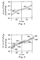
- the output voltage of the instrument was recorded in a digital format using a personal computer. A typical graph output is shown in Figure 4. At the start of the test there was no tension on the sample. As the test begins the load cell begins to experience a load as the sample is bent. The initial rotation was clockwise when viewed from the top down on the instrument.
- a linear regression line was obtained between approximately 0.2 and 0.7cm -1 for the Forward Bend (FB) and the Forward Bend Return (FR).
- a linear regression line was obtained between approximately -0.2 and -0.7cm -1 for the Backward Bend (BB) and the Backward Bend Return (BR), as shown Figure 5 which shows linear regression lines between 0.2 and 0.7cm -1 for the Forward Bend (FB) Forward Bend Return (FR) and between -0.2 and -0.7cm -1 for the Backward Bend (BB) and the Backward Bend Return (BR).
- the slope of the line is the Bending Stiffness (B). It has units of gf*cm 2 /cm.
- the caliper, or thickness, t of the reinforcing structure 12 is measured using an Emveco Model 210A digital micrometer made by the Emveco Company of Newburg, Oregon, or similar apparatus, using a 20.6841 kPA (3.0 psi) loading applied through a round 2.2225 cm (0.875 inch) diameter foot.
- the reinforcing structure 12 is loaded to 3.57 kg per cm (20 pounds per lineal inch) in the machine direction while tested for thickness.
- the reinforcing structure 12 should be maintained at about 21.11°C (70°F) during testing.
- Void volume of the reinforcing structure, prior to application of the pattern laye is determined by the following method.
- a four -2.54 cm (four-inch) square (103.2cm 2 - 16in 2 ) piece of reinforcing structure is measured for caliper (by the method above) and weighed.
- the density of the constituent yarns is determined; the density of the void spaces is assumed to be 0 gm/cc.
- PET polyester
- the four -2.54 cm (four-inch) square is weighed, thereby yielding the mass of the test sample.
- Void volume per square inch of reinforcing structure is then calculated by dividing the calculated void volume by the area (16 in 2 ) of the test sample (again, assuring that all units are converted and consistent).
Landscapes
- Paper (AREA)
- Woven Fabrics (AREA)
Applications Claiming Priority (3)
| Application Number | Priority Date | Filing Date | Title |
|---|---|---|---|
| US09/056,350 US6103067A (en) | 1998-04-07 | 1998-04-07 | Papermaking belt providing improved drying efficiency for cellulosic fibrous structures |
| US56350 | 1998-04-07 | ||
| PCT/IB1999/000583 WO1999051814A1 (en) | 1998-04-07 | 1999-04-05 | Papermaking belt providing improved drying efficiency for cellulosic fibrous structures |
Publications (2)
| Publication Number | Publication Date |
|---|---|
| EP1070172A1 EP1070172A1 (en) | 2001-01-24 |
| EP1070172B1 true EP1070172B1 (en) | 2003-03-05 |
Family
ID=22003832
Family Applications (1)
| Application Number | Title | Priority Date | Filing Date |
|---|---|---|---|
| EP99909152A Expired - Lifetime EP1070172B1 (en) | 1998-04-07 | 1999-04-05 | Papermaking belt providing improved drying efficiency for cellulosic fibrous structures |
Country Status (24)
| Country | Link |
|---|---|
| US (2) | US6103067A (https=) |
| EP (1) | EP1070172B1 (https=) |
| JP (1) | JP2002510757A (https=) |
| KR (1) | KR20010042437A (https=) |
| CN (1) | CN1300331A (https=) |
| AR (1) | AR018843A1 (https=) |
| AT (1) | ATE233844T1 (https=) |
| AU (1) | AU749598B2 (https=) |
| BR (1) | BR9909532A (https=) |
| CA (1) | CA2327802C (https=) |
| CO (1) | CO5070725A1 (https=) |
| CZ (1) | CZ20003393A3 (https=) |
| DE (1) | DE69905702T2 (https=) |
| ES (1) | ES2193691T3 (https=) |
| HU (1) | HUP0103223A3 (https=) |
| ID (1) | ID29196A (https=) |
| IL (1) | IL138448A0 (https=) |
| NO (1) | NO20005091L (https=) |
| PE (1) | PE20010782A1 (https=) |
| PL (1) | PL343237A1 (https=) |
| TR (1) | TR200002811T2 (https=) |
| TW (1) | TW541384B (https=) |
| WO (1) | WO1999051814A1 (https=) |
| ZA (1) | ZA200005155B (https=) |
Families Citing this family (24)
| Publication number | Priority date | Publication date | Assignee | Title |
|---|---|---|---|---|
| DE19837182B4 (de) * | 1998-08-17 | 2007-01-25 | Stahlecker, Fritz | Transportband zum Transportieren eines zu verdichtenden Faserverbandes |
| WO2000034571A1 (en) * | 1998-12-07 | 2000-06-15 | Valmet-Karlstad Ab | Wire part and press therefor |
| JP4772237B2 (ja) * | 2001-09-26 | 2011-09-14 | シキボウ株式会社 | 工業用ベルト |
| US6749719B2 (en) | 2001-11-02 | 2004-06-15 | Kimberly-Clark Worldwide, Inc. | Method of manufacture tissue products having visually discernable background texture regions bordered by curvilinear decorative elements |
| US6787000B2 (en) | 2001-11-02 | 2004-09-07 | Kimberly-Clark Worldwide, Inc. | Fabric comprising nonwoven elements for use in the manufacture of tissue products having visually discernable background texture regions bordered by curvilinear decorative elements and method thereof |
| US6746570B2 (en) | 2001-11-02 | 2004-06-08 | Kimberly-Clark Worldwide, Inc. | Absorbent tissue products having visually discernable background texture |
| US6821385B2 (en) | 2001-11-02 | 2004-11-23 | Kimberly-Clark Worldwide, Inc. | Method of manufacture of tissue products having visually discernable background texture regions bordered by curvilinear decorative elements using fabrics comprising nonwoven elements |
| US6790314B2 (en) | 2001-11-02 | 2004-09-14 | Kimberly-Clark Worldwide, Inc. | Fabric for use in the manufacture of tissue products having visually discernable background texture regions bordered by curvilinear decorative elements and method thereof |
| US7048012B2 (en) * | 2002-10-24 | 2006-05-23 | Albany International Corp. | Paired warp triple layer forming fabrics with optimum sheet building characteristics |
| US6834684B2 (en) * | 2002-10-24 | 2004-12-28 | Albany International Corp. | Paired warp triple layer forming fabrics with optimum sheet building characteristics |
| US7959764B2 (en) * | 2007-06-13 | 2011-06-14 | Voith Patent Gmbh | Forming fabrics for fiber webs |
| DE502007007082D1 (de) * | 2007-12-04 | 2011-06-09 | Heimbach Gmbh & Co Kg | Formiersieb für den Einsatz in einer Papiermaschine |
| US8251103B2 (en) * | 2009-11-04 | 2012-08-28 | Weavexx Corporation | Papermaker's forming fabric with engineered drainage channels |
| FR2953864B1 (fr) * | 2009-12-11 | 2012-01-06 | Procter & Gamble | Courroie pour la fabrication du papier |
| FR2953863B1 (fr) * | 2009-12-11 | 2012-01-06 | Procter & Gamble | Courroie pour la fabrication du papier |
| US8298376B2 (en) * | 2010-08-19 | 2012-10-30 | The Procter & Gamble Company | Patterned framework for a papermaking belt |
| US8313617B2 (en) * | 2010-08-19 | 2012-11-20 | The Procter & Gamble Company | Patterned framework for a papermaking belt |
| KR102463905B1 (ko) | 2014-09-25 | 2022-11-04 | 쥐피씨피 아이피 홀딩스 엘엘씨 | 다층 크레이핑 벨트를 사용하여 종이 제품을 제조하는 방법 및 다층 크레이핑 벨트를 사용하여 제조된 종이 제품 |
| EP3023084B1 (en) | 2014-11-18 | 2020-06-17 | The Procter and Gamble Company | Absorbent article and distribution material |
| US10517775B2 (en) | 2014-11-18 | 2019-12-31 | The Procter & Gamble Company | Absorbent articles having distribution materials |
| US10765570B2 (en) | 2014-11-18 | 2020-09-08 | The Procter & Gamble Company | Absorbent articles having distribution materials |
| WO2017156203A1 (en) | 2016-03-11 | 2017-09-14 | The Procter & Gamble Company | A three-dimensional substrate comprising a tissue layer |
| JP2024034396A (ja) * | 2022-08-31 | 2024-03-13 | イチカワ株式会社 | 製紙用ベルト |
| JP2024034395A (ja) * | 2022-08-31 | 2024-03-13 | イチカワ株式会社 | 製紙用ベルト |
Family Cites Families (28)
| Publication number | Priority date | Publication date | Assignee | Title |
|---|---|---|---|---|
| US4528239A (en) * | 1983-08-23 | 1985-07-09 | The Procter & Gamble Company | Deflection member |
| US4637859A (en) * | 1983-08-23 | 1987-01-20 | The Procter & Gamble Company | Tissue paper |
| US4514345A (en) * | 1983-08-23 | 1985-04-30 | The Procter & Gamble Company | Method of making a foraminous member |
| US4529480A (en) * | 1983-08-23 | 1985-07-16 | The Procter & Gamble Company | Tissue paper |
| US5114777B2 (en) * | 1985-08-05 | 1997-11-18 | Wangner Systems Corp | Woven multilayer papermaking fabric having increased stability and permeability and method |
| US5066532A (en) * | 1985-08-05 | 1991-11-19 | Hermann Wangner Gmbh & Co. | Woven multilayer papermaking fabric having increased stability and permeability and method |
| US5324392A (en) * | 1989-04-18 | 1994-06-28 | Nippon Filcon Co., Ltd. | Extendable and heat shrinkable polyamide mono-filament for endless fabric and endless fabric |
| CA2155223C (en) * | 1990-06-29 | 1997-11-11 | Paul Dennis Trokhan | Papermaking fabric |
| US5275700A (en) * | 1990-06-29 | 1994-01-04 | The Procter & Gamble Company | Papermaking belt and method of making the same using a deformable casting surface |
| US5260171A (en) * | 1990-06-29 | 1993-11-09 | The Procter & Gamble Company | Papermaking belt and method of making the same using a textured casting surface |
| US5098522A (en) * | 1990-06-29 | 1992-03-24 | The Procter & Gamble Company | Papermaking belt and method of making the same using a textured casting surface |
| US5679222A (en) * | 1990-06-29 | 1997-10-21 | The Procter & Gamble Company | Paper having improved pinhole characteristics and papermaking belt for making the same |
| CA2069193C (en) * | 1991-06-19 | 1996-01-09 | David M. Rasch | Tissue paper having large scale aesthetically discernible patterns and apparatus for making the same |
| US5245025A (en) * | 1991-06-28 | 1993-09-14 | The Procter & Gamble Company | Method and apparatus for making cellulosic fibrous structures by selectively obturated drainage and cellulosic fibrous structures produced thereby |
| US5274930A (en) * | 1992-06-30 | 1994-01-04 | The Procter & Gamble Company | Limiting orifice drying of cellulosic fibrous structures, apparatus therefor, and cellulosic fibrous structures produced thereby |
| AU683428B2 (en) * | 1992-08-26 | 1997-11-13 | Procter & Gamble Company, The | A secondary papermaking belt having a semicontinuous pattern of protuberances and paper made thereon |
| US5366798A (en) * | 1993-11-30 | 1994-11-22 | Wangner Systems Corporation | Multi-layered papermaking fabric having stabilized stacked weft yarn |
| CN1070964C (zh) * | 1993-12-20 | 2001-09-12 | 普罗克特和甘保尔公司 | 湿压榨纸幅及其制造方法 |
| US5496624A (en) * | 1994-06-02 | 1996-03-05 | The Procter & Gamble Company | Multiple layer papermaking belt providing improved fiber support for cellulosic fibrous structures, and cellulosic fibrous structures produced thereby |
| US5500277A (en) * | 1994-06-02 | 1996-03-19 | The Procter & Gamble Company | Multiple layer, multiple opacity backside textured belt |
| US5549790A (en) * | 1994-06-29 | 1996-08-27 | The Procter & Gamble Company | Multi-region paper structures having a transition region interconnecting relatively thinner regions disposed at different elevations, and apparatus and process for making the same |
| US5556509A (en) * | 1994-06-29 | 1996-09-17 | The Procter & Gamble Company | Paper structures having at least three regions including a transition region interconnecting relatively thinner regions disposed at different elevations, and apparatus and process for making the same |
| US5496625A (en) | 1994-12-30 | 1996-03-05 | Norfab Corporation | Melamine thermal protective fabric and core-spun heat resistant yarn for making the same |
| US5629052A (en) * | 1995-02-15 | 1997-05-13 | The Procter & Gamble Company | Method of applying a curable resin to a substrate for use in papermaking |
| JP4073954B2 (ja) * | 1995-02-15 | 2008-04-09 | ザ プロクター アンド ギャンブル カンパニー | 製紙に使用するための基質に硬化性樹脂を塗布する方法 |
| US5581906A (en) * | 1995-06-07 | 1996-12-10 | The Procter & Gamble Company | Multiple zone limiting orifice drying of cellulosic fibrous structures apparatus therefor, and cellulosic fibrous structures produced thereby |
| GB9609761D0 (en) * | 1996-05-10 | 1996-07-17 | Jwi Ltd | Low air permeability papermaking fabric including flattened secondary weft yarns and pin seam |
| SE511107C2 (sv) * | 1997-12-15 | 1999-08-09 | Albany Int Corp | Vävd vira |
-
1998
- 1998-04-07 US US09/056,350 patent/US6103067A/en not_active Expired - Lifetime
-
1999
- 1999-04-05 ES ES99909152T patent/ES2193691T3/es not_active Expired - Lifetime
- 1999-04-05 CZ CZ20003393A patent/CZ20003393A3/cs unknown
- 1999-04-05 WO PCT/IB1999/000583 patent/WO1999051814A1/en not_active Ceased
- 1999-04-05 CA CA002327802A patent/CA2327802C/en not_active Expired - Fee Related
- 1999-04-05 EP EP99909152A patent/EP1070172B1/en not_active Expired - Lifetime
- 1999-04-05 TR TR2000/02811T patent/TR200002811T2/xx unknown
- 1999-04-05 DE DE69905702T patent/DE69905702T2/de not_active Expired - Lifetime
- 1999-04-05 IL IL13844899A patent/IL138448A0/xx unknown
- 1999-04-05 HU HU0103223A patent/HUP0103223A3/hu unknown
- 1999-04-05 CN CN99806033A patent/CN1300331A/zh active Pending
- 1999-04-05 KR KR1020007011031A patent/KR20010042437A/ko not_active Ceased
- 1999-04-05 AT AT99909152T patent/ATE233844T1/de not_active IP Right Cessation
- 1999-04-05 BR BR9909532-7A patent/BR9909532A/pt not_active IP Right Cessation
- 1999-04-05 ID IDW20002024A patent/ID29196A/id unknown
- 1999-04-05 JP JP2000542522A patent/JP2002510757A/ja active Pending
- 1999-04-05 AU AU28499/99A patent/AU749598B2/en not_active Ceased
- 1999-04-05 PL PL99343237A patent/PL343237A1/xx unknown
- 1999-04-07 CO CO99020383A patent/CO5070725A1/es unknown
- 1999-04-07 PE PE1999000282A patent/PE20010782A1/es not_active Application Discontinuation
- 1999-04-07 AR ARP990101571A patent/AR018843A1/es not_active Application Discontinuation
- 1999-04-07 TW TW088105487A patent/TW541384B/zh active
-
2000
- 2000-05-19 US US09/575,048 patent/US6368465B1/en not_active Expired - Lifetime
- 2000-09-26 ZA ZA200005155A patent/ZA200005155B/en unknown
- 2000-10-09 NO NO20005091A patent/NO20005091L/no not_active Application Discontinuation
Also Published As
| Publication number | Publication date |
|---|---|
| CA2327802A1 (en) | 1999-10-14 |
| TR200002811T2 (tr) | 2001-01-22 |
| US6368465B1 (en) | 2002-04-09 |
| TW541384B (en) | 2003-07-11 |
| WO1999051814A1 (en) | 1999-10-14 |
| AU749598B2 (en) | 2002-06-27 |
| AR018843A1 (es) | 2001-12-12 |
| PE20010782A1 (es) | 2001-08-12 |
| HUP0103223A2 (hu) | 2002-01-28 |
| ATE233844T1 (de) | 2003-03-15 |
| ID29196A (id) | 2001-08-09 |
| CO5070725A1 (es) | 2001-08-28 |
| PL343237A1 (en) | 2001-07-30 |
| JP2002510757A (ja) | 2002-04-09 |
| NO20005091D0 (no) | 2000-10-09 |
| IL138448A0 (en) | 2001-10-31 |
| HUP0103223A3 (en) | 2002-03-28 |
| DE69905702T2 (de) | 2003-10-02 |
| CA2327802C (en) | 2006-03-21 |
| KR20010042437A (ko) | 2001-05-25 |
| NO20005091L (no) | 2000-10-09 |
| CZ20003393A3 (cs) | 2001-12-12 |
| ZA200005155B (en) | 2002-01-09 |
| AU2849999A (en) | 1999-10-25 |
| ES2193691T3 (es) | 2003-11-01 |
| CN1300331A (zh) | 2001-06-20 |
| DE69905702D1 (de) | 2003-04-10 |
| BR9909532A (pt) | 2000-12-12 |
| US6103067A (en) | 2000-08-15 |
| EP1070172A1 (en) | 2001-01-24 |
Similar Documents
| Publication | Publication Date | Title |
|---|---|---|
| EP1070172B1 (en) | Papermaking belt providing improved drying efficiency for cellulosic fibrous structures | |
| KR100336143B1 (ko) | 개량된섬유질서포트를구비한3중층제지패브릭 | |
| AU774933B2 (en) | Papermaking apparatus and process for removing water from a cellulosic web | |
| US5840411A (en) | Multiple layer papermaking belt providing improved fiber support for cellulosic fibrous structures, and cellulosic fibrous structures produced thereby | |
| CA2599939C (en) | Double layer forming fabric with paired warp binder yarns | |
| KR20010024095A (ko) | 퓨지티브 연결 얀을 갖는 다층 유공성 벨트 | |
| AU773448B2 (en) | Papermaking belt providing improved drying efficiency for cellulosic fibrous structures | |
| US7682995B2 (en) | Triple layer industrial fabric for through-air drying process | |
| MXPA00009832A (en) | Papermaking belt providing improved drying efficiency for cellulosic fibrous structures |
Legal Events
| Date | Code | Title | Description |
|---|---|---|---|
| PUAI | Public reference made under article 153(3) epc to a published international application that has entered the european phase |
Free format text: ORIGINAL CODE: 0009012 |
|
| 17P | Request for examination filed |
Effective date: 20001109 |
|
| AK | Designated contracting states |
Kind code of ref document: A1 Designated state(s): AT BE CH CY DE DK ES FI FR GB GR IE IT LI LU NL PT SE |
|
| 17Q | First examination report despatched |
Effective date: 20010528 |
|
| GRAG | Despatch of communication of intention to grant |
Free format text: ORIGINAL CODE: EPIDOS AGRA |
|
| GRAG | Despatch of communication of intention to grant |
Free format text: ORIGINAL CODE: EPIDOS AGRA |
|
| GRAH | Despatch of communication of intention to grant a patent |
Free format text: ORIGINAL CODE: EPIDOS IGRA |
|
| GRAH | Despatch of communication of intention to grant a patent |
Free format text: ORIGINAL CODE: EPIDOS IGRA |
|
| GRAA | (expected) grant |
Free format text: ORIGINAL CODE: 0009210 |
|
| AK | Designated contracting states |
Designated state(s): AT BE CH CY DE DK ES FI FR GB GR IE IT LI LU NL PT SE |
|
| PG25 | Lapsed in a contracting state [announced via postgrant information from national office to epo] |
Ref country code: GR Free format text: LAPSE BECAUSE OF FAILURE TO SUBMIT A TRANSLATION OF THE DESCRIPTION OR TO PAY THE FEE WITHIN THE PRESCRIBED TIME-LIMIT Effective date: 20030305 Ref country code: AT Free format text: LAPSE BECAUSE OF FAILURE TO SUBMIT A TRANSLATION OF THE DESCRIPTION OR TO PAY THE FEE WITHIN THE PRESCRIBED TIME-LIMIT Effective date: 20030305 |
|
| REG | Reference to a national code |
Ref country code: GB Ref legal event code: FG4D |
|
| REG | Reference to a national code |
Ref country code: CH Ref legal event code: NV Representative=s name: RITSCHER & PARTNER AG PATENTANWAELTE Ref country code: CH Ref legal event code: EP |
|
| PGFP | Annual fee paid to national office [announced via postgrant information from national office to epo] |
Ref country code: NL Payment date: 20030318 Year of fee payment: 5 |
|
| REG | Reference to a national code |
Ref country code: IE Ref legal event code: FG4D |
|
| PG25 | Lapsed in a contracting state [announced via postgrant information from national office to epo] |
Ref country code: LU Free format text: LAPSE BECAUSE OF NON-PAYMENT OF DUE FEES Effective date: 20030405 Ref country code: CY Free format text: LAPSE BECAUSE OF FAILURE TO SUBMIT A TRANSLATION OF THE DESCRIPTION OR TO PAY THE FEE WITHIN THE PRESCRIBED TIME-LIMIT Effective date: 20030405 |
|
| PG25 | Lapsed in a contracting state [announced via postgrant information from national office to epo] |
Ref country code: IE Free format text: LAPSE BECAUSE OF NON-PAYMENT OF DUE FEES Effective date: 20030407 |
|
| REF | Corresponds to: |
Ref document number: 69905702 Country of ref document: DE Date of ref document: 20030410 Kind code of ref document: P |
|
| PGFP | Annual fee paid to national office [announced via postgrant information from national office to epo] |
Ref country code: FI Payment date: 20030411 Year of fee payment: 5 |
|
| PGFP | Annual fee paid to national office [announced via postgrant information from national office to epo] |
Ref country code: ES Payment date: 20030425 Year of fee payment: 5 |
|
| PGFP | Annual fee paid to national office [announced via postgrant information from national office to epo] |
Ref country code: BE Payment date: 20030514 Year of fee payment: 5 |
|
| PG25 | Lapsed in a contracting state [announced via postgrant information from national office to epo] |
Ref country code: PT Free format text: LAPSE BECAUSE OF FAILURE TO SUBMIT A TRANSLATION OF THE DESCRIPTION OR TO PAY THE FEE WITHIN THE PRESCRIBED TIME-LIMIT Effective date: 20030605 Ref country code: DK Free format text: LAPSE BECAUSE OF FAILURE TO SUBMIT A TRANSLATION OF THE DESCRIPTION OR TO PAY THE FEE WITHIN THE PRESCRIBED TIME-LIMIT Effective date: 20030605 |
|
| PGFP | Annual fee paid to national office [announced via postgrant information from national office to epo] |
Ref country code: CH Payment date: 20030605 Year of fee payment: 5 |
|
| REG | Reference to a national code |
Ref country code: SE Ref legal event code: TRGR |
|
| ET | Fr: translation filed | ||
| REG | Reference to a national code |
Ref country code: ES Ref legal event code: FG2A Ref document number: 2193691 Country of ref document: ES Kind code of ref document: T3 |
|
| PLBE | No opposition filed within time limit |
Free format text: ORIGINAL CODE: 0009261 |
|
| STAA | Information on the status of an ep patent application or granted ep patent |
Free format text: STATUS: NO OPPOSITION FILED WITHIN TIME LIMIT |
|
| REG | Reference to a national code |
Ref country code: IE Ref legal event code: MM4A |
|
| 26N | No opposition filed |
Effective date: 20031208 |
|
| PG25 | Lapsed in a contracting state [announced via postgrant information from national office to epo] |
Ref country code: FI Free format text: LAPSE BECAUSE OF NON-PAYMENT OF DUE FEES Effective date: 20040405 |
|
| PG25 | Lapsed in a contracting state [announced via postgrant information from national office to epo] |
Ref country code: ES Free format text: LAPSE BECAUSE OF NON-PAYMENT OF DUE FEES Effective date: 20040406 |
|
| PG25 | Lapsed in a contracting state [announced via postgrant information from national office to epo] |
Ref country code: LI Free format text: LAPSE BECAUSE OF NON-PAYMENT OF DUE FEES Effective date: 20040430 Ref country code: CH Free format text: LAPSE BECAUSE OF NON-PAYMENT OF DUE FEES Effective date: 20040430 Ref country code: BE Free format text: LAPSE BECAUSE OF NON-PAYMENT OF DUE FEES Effective date: 20040430 |
|
| BERE | Be: lapsed |
Owner name: THE *PROCTER & GAMBLE CY Effective date: 20040430 |
|
| PG25 | Lapsed in a contracting state [announced via postgrant information from national office to epo] |
Ref country code: NL Free format text: LAPSE BECAUSE OF NON-PAYMENT OF DUE FEES Effective date: 20041101 |
|
| REG | Reference to a national code |
Ref country code: CH Ref legal event code: PL |
|
| NLV4 | Nl: lapsed or anulled due to non-payment of the annual fee |
Effective date: 20041101 |
|
| REG | Reference to a national code |
Ref country code: ES Ref legal event code: FD2A Effective date: 20040406 |
|
| PGFP | Annual fee paid to national office [announced via postgrant information from national office to epo] |
Ref country code: GB Payment date: 20140325 Year of fee payment: 16 |
|
| PGFP | Annual fee paid to national office [announced via postgrant information from national office to epo] |
Ref country code: DE Payment date: 20140430 Year of fee payment: 16 Ref country code: IT Payment date: 20140414 Year of fee payment: 16 Ref country code: FR Payment date: 20140328 Year of fee payment: 16 Ref country code: SE Payment date: 20140408 Year of fee payment: 16 |
|
| REG | Reference to a national code |
Ref country code: DE Ref legal event code: R119 Ref document number: 69905702 Country of ref document: DE |
|
| REG | Reference to a national code |
Ref country code: SE Ref legal event code: EUG |
|
| GBPC | Gb: european patent ceased through non-payment of renewal fee |
Effective date: 20150405 |
|
| PG25 | Lapsed in a contracting state [announced via postgrant information from national office to epo] |
Ref country code: DE Free format text: LAPSE BECAUSE OF NON-PAYMENT OF DUE FEES Effective date: 20151103 Ref country code: IT Free format text: LAPSE BECAUSE OF NON-PAYMENT OF DUE FEES Effective date: 20150405 Ref country code: GB Free format text: LAPSE BECAUSE OF NON-PAYMENT OF DUE FEES Effective date: 20150405 |
|
| REG | Reference to a national code |
Ref country code: FR Ref legal event code: ST Effective date: 20151231 |
|
| PG25 | Lapsed in a contracting state [announced via postgrant information from national office to epo] |
Ref country code: SE Free format text: LAPSE BECAUSE OF NON-PAYMENT OF DUE FEES Effective date: 20150406 Ref country code: FR Free format text: LAPSE BECAUSE OF NON-PAYMENT OF DUE FEES Effective date: 20150430 |