EP1069803A2 - Loudspeaker - Google Patents
Loudspeaker Download PDFInfo
- Publication number
- EP1069803A2 EP1069803A2 EP00305298A EP00305298A EP1069803A2 EP 1069803 A2 EP1069803 A2 EP 1069803A2 EP 00305298 A EP00305298 A EP 00305298A EP 00305298 A EP00305298 A EP 00305298A EP 1069803 A2 EP1069803 A2 EP 1069803A2
- Authority
- EP
- European Patent Office
- Prior art keywords
- loudspeaker
- channel
- central member
- transverse cross
- housing
- Prior art date
- Legal status (The legal status is an assumption and is not a legal conclusion. Google has not performed a legal analysis and makes no representation as to the accuracy of the status listed.)
- Granted
Links
Images

Classifications
-
- H—ELECTRICITY
- H04—ELECTRIC COMMUNICATION TECHNIQUE
- H04R—LOUDSPEAKERS, MICROPHONES, GRAMOPHONE PICK-UPS OR LIKE ACOUSTIC ELECTROMECHANICAL TRANSDUCERS; ELECTRIC HEARING AIDS; PUBLIC ADDRESS SYSTEMS
- H04R1/00—Details of transducers, loudspeakers or microphones
- H04R1/20—Arrangements for obtaining desired frequency or directional characteristics
- H04R1/32—Arrangements for obtaining desired frequency or directional characteristics for obtaining desired directional characteristic only
- H04R1/34—Arrangements for obtaining desired frequency or directional characteristics for obtaining desired directional characteristic only by using a single transducer with sound reflecting, diffracting, directing or guiding means
Definitions
- the present invention relates to a loudspeaker.
- the invention relates to a loudspeaker of the upper bass/low mid type which may be used with loudspeakers covering other parts of the audible sound frequency spectrum in high quality public address (PA) systems.
- PA public address
- the range or spectrum of audible sound frequencies is generally taken to extend from about 15Hz to about 20KHz. It is well known to divide this frequency range into several notional contiguous ranges with each such range being catered for by a loudspeaker whose design is largely dictated by the sub-range which it is required to handle.
- a typical example of such sub-ranges is as follows:
- an upper bass/low mid loudspeaker comprising: an electro-acoustic driver having a conical diaphragm; and a housing and a central member defining a channel for the propagation of sound from the front of the diaphragm, characterised in that the central member has a first portion extending into the volume defined by the diaphragm and defining with the diaphragm a first region of the channel of ring-shaped cross-section whose transverse cross-sectional area increases in the direction of sound propagation within the channel, the central member having a second portion disposed within a first portion of the housing to define a second region of the channel of ring-shaped cross-section whose transverse cross-sectional area decreases in the direction of sound propagation within the channel, the housing having a second portion defining a throat extending from the second region and a third portion defining a horn extending from the throat.
- the first portion of the central member may have a transverse cross-sectional area which increases in the direction of sound propagation within the channel and the second portion of the central member may have a transverse cross-sectional area which decreases in the direction of sound propagation within the channel.
- the throat may have a transverse cross-sectional area which increases at a first rate in the direction of sound propagation within the channel.
- the horn may have a transverse cross-sectional area which increases at a second rate greater than the first rate in the direction of sound propagation within the channel.
- the central member may have a third portion extending within the second portion of the housing and defining therebetween the throat which is of ring-shaped transverse cross-section.
- the central member may have a fourth portion extending into the horn.
- the fourth portion of the central member may have a substantially hemispherical end.
- the central member may have a substantially circular transverse cross-sectional shape throughout its extent in the direction of sound propagation within the channel.
- the housing may have a substantially rectangular transverse cross-sectional shape throughout its extent in the direction of sound propagation within the channel.
- the housing may have a substantially parallel pair of internal surfaces.
- the channel may be folded, for example at or adjacent the transition between the second region and the throat.
- the loudspeaker may comprise an enclosure at the rear of the driver forming therewith a substantially sealed chamber.
- a PA system including a loudspeaker according to the first aspect of the invention.
- ring-shaped as used herein means annular or isomorphic thereto.
- the central member is disposed inside the housing but does not touch it so that, at each cross-section transverse to the direction of sound propagation within the channel, the housing is spaced from the central member all the way around the central member.
- transverse cross-section means a section in a plane which is substantially perpendicular to the local direction of sound propagation within the channel.
- an upper bass/low mid loudspeaker which is capable of covering up to about a decade, for example from about 75Hz to about 750Hz.
- a smooth frequency response, fast transient response and high efficiency can be provided.
- a good dispersion pattern for example in the horizontal plane, can be provided.
- Such a loudspeaker is suitable for use in PA system, for example for concerts where high quality high level sound is required.
- the loudspeaker shown in Figures 1 to 3 is for use at upper bass/low mid frequencies, for example as part of a loudspeaker system of a PA system.
- the loudspeaker comprises a cone driver 1.
- the driver 1 comprises a conical diaphragm 2 and a magnet structure with a central pole piece 3.
- the front of the driver chassis is mounted on a baffle 4 and an enclosure illustrated diagrammatically at 5 in Figure 2 is disposed behind the driver 1 and attached to the baffle 4 so as to form a sealed chamber behind the driver 1.
- the loudspeaker comprises a central member 6 and housing 7 which define a channel for propagation of sound from the front of the diaphragm 2 to the exterior of the housing 7.
- the central member 6 is of circular transverse cross-section throughout its length and is attached at its rear to the pole piece 3.
- the central member 6 has a first portion 8 which extends into the conical volume defined by the diaphragm 2.
- the first portion 8 and the diaphragm 2 define a first region 9 of the channel of annular transverse cross-sectional shape.
- the transverse cross-sectional area of the first region 9 increases in the direction of sound propagation within the channel i.e. from the pole piece 3 approximately to the plane of the baffle 4.
- the transverse cross-sectional area of the first portion 8 increases in the direction of sound propagation.
- the central member 6 has a second portion 10 whose transverse cross-sectional area decreases in the direction of sound propagation.
- the second portion 10 is disposed centrally inside a first portion 11 of the housing 7 and defines therewith a ring-shaped second region 12 of the channel whose transverse cross-sectional area decreases in the direction of sound propagation.
- the housing 7 has a second portion 13 which cooperates with a third portion 14 of the central member 6 to define a throat 15 which extends from the second region 12.
- the housing 7 has a third portion 16 which defines a horn 17 extending from the throat 15.
- the central member 6 has a fourth portion 18 of substantially hemispherical shape which projects into the start of the horn 17.
- the central member 6 is circularly symmetrical about the longitudinal axis of the loudspeaker (coaxial with the direction of sound propagation within the channel). Thus, the transverse cross-sectional shape of the central member 6 is circular throughout its length.
- the throat 15 has a transverse cross-sectional area which increases at a first rate in the direction of propagation.
- the horn 17 has a transverse cross-sectional area which increases, in the direction of propagation, at a second rate which is greater than the first rate.
- the transverse cross-sectional area of the third portion 14 of the central member 6 is substantially constant throughout the throat 15 or most thereof .
- the housing 7 comprises upper and lower surfaces 20 and 21 which are substantially parallel and, in use, are disposed in parallel horizontal planes.
- the transverse cross-sectional shapes of the channel are illustrated in Figure 3 at various positions (labelled A to G in Figure 2) along the length of the loudspeaker from the plane of the baffle (A) to the plane of the mouth (G) of the horn 17.
- the varying circular cross-section of the central member 6 is clearly shown in cross-sections A-A to E-E.
- the housing 7 Forward of the baffle 10, the housing 7 is of rectangular cross-section with the width varying throughout the length of the loudspeaker but with the height being substantially constant.
- the channel is therefore ring-shaped in transverse section throughout its length to the end of the hemispherical fourth portion 18 of the central member 6.
- a loudspeaker of the type shown in Figures 1 to 3 is capable of operating over approximately a decade from about 75 to about 750Hz.
- a function of the central member 6 is to maintain coherence in the upper part of the frequency spectrum of the loudspeaker and to move upwardly the whole frequency band of which the loudspeaker would be capable in the absence of the central member 6.
- the "constriction" which occurs in the second region 12 just before the throat 15 compensates for the loss of low frequencies caused by the central member 6 by lowering the low frequency cut-off-point of the loudspeaker, it is believed that, typically in the absence of the constriction, the lower end of the frequency range would be about 150 to 200Hz. However, the presence of the constriction lowers this to about 75Hz.
- the combined effect is to provide a loudspeaker having excellent coherence across a large frequency band.
- the loudspeaker provides very high output levels with high electro-acoustic efficiency, typically giving an acoustic output of 107 dB at one metre for an electrical input of one watt. Also, a wide and uniform dispersion pattern in the horizontal plane can be provided, as is typically required of PA systems.
- the loudspeaker has a smooth frequency response within its operating range and a fast transient response. All of these features make the loudspeaker suitable for use in very high quality PA systems.
- the loudspeaker shown in Figure 1 has an essentially straight acoustic channel within which the sound propagates from the diaphragm 2 to the exterior. Such a loudspeaker occupies a substantial area in the horizontal plane. However, as shown in Figure 4, it is possible to provide a more compact loudspeaker of a type similar to that in Figure 1 by folding the channel.
- the loudspeaker shown in Figure 4 differs from that shown in Figure 1 in two essential ways.
- the acoustic channel is bent around a vertical axis at or near the transition 24 between the second region 12 and the throat 15.
- the central member 6 comprises only the first and second portions 8 and 10.
- the height of the housing 7 is substantially constant and the whole loudspeaker is contained between parallel upper and lower walls.
- the loudspeaker shown in Figure 4 is acoustically similar to that shown in Figure 1 but occupies substantially less space.
- Figure 4 also illustrates the sealed chamber 25 acting as an enclosure behind the driver 1.
Landscapes
- Health & Medical Sciences (AREA)
- Otolaryngology (AREA)
- Physics & Mathematics (AREA)
- Engineering & Computer Science (AREA)
- Acoustics & Sound (AREA)
- Signal Processing (AREA)
- Obtaining Desirable Characteristics In Audible-Bandwidth Transducers (AREA)
- Audible-Bandwidth Dynamoelectric Transducers Other Than Pickups (AREA)
- Chair Legs, Seat Parts, And Backrests (AREA)
- Liquid Crystal (AREA)
- Surgical Instruments (AREA)
Abstract
Description
- The present invention relates to a loudspeaker. In particular, the invention relates to a loudspeaker of the upper bass/low mid type which may be used with loudspeakers covering other parts of the audible sound frequency spectrum in high quality public address (PA) systems.
- The range or spectrum of audible sound frequencies is generally taken to extend from about 15Hz to about 20KHz. It is well known to divide this frequency range into several notional contiguous ranges with each such range being catered for by a loudspeaker whose design is largely dictated by the sub-range which it is required to handle. A typical example of such sub-ranges is as follows:
- Bass
- 35-175 Hz
- Low Mid
- 175-1600 Hz
- High Mid
- 1600-5000 Hz
- Treble
- 5000-18000 Hz
- It has been found that the sub-ranges into which large PA systems are divided do not represent the best division of acoustic energy. Even in the best "four way" systems (i.e. systems having four sub-ranges), there is usually a "muddy" and ill-defined frequency area straddling the used 150-200Hz cross-over point between the bass and low mid sub-ranges. This unsatisfactory area extends from about 120Hz to about 350Hz.
- According to a first aspect of the invention, there is provided an upper bass/low mid loudspeaker comprising: an electro-acoustic driver having a conical diaphragm; and a housing and a central member defining a channel for the propagation of sound from the front of the diaphragm, characterised in that the central member has a first portion extending into the volume defined by the diaphragm and defining with the diaphragm a first region of the channel of ring-shaped cross-section whose transverse cross-sectional area increases in the direction of sound propagation within the channel, the central member having a second portion disposed within a first portion of the housing to define a second region of the channel of ring-shaped cross-section whose transverse cross-sectional area decreases in the direction of sound propagation within the channel, the housing having a second portion defining a throat extending from the second region and a third portion defining a horn extending from the throat.
- The first portion of the central member may have a transverse cross-sectional area which increases in the direction of sound propagation within the channel and the second portion of the central member may have a transverse cross-sectional area which decreases in the direction of sound propagation within the channel.
- The throat may have a transverse cross-sectional area which increases at a first rate in the direction of sound propagation within the channel. The horn may have a transverse cross-sectional area which increases at a second rate greater than the first rate in the direction of sound propagation within the channel.
- The central member may have a third portion extending within the second portion of the housing and defining therebetween the throat which is of ring-shaped transverse cross-section. The central member may have a fourth portion extending into the horn. The fourth portion of the central member may have a substantially hemispherical end.
- The central member may have a substantially circular transverse cross-sectional shape throughout its extent in the direction of sound propagation within the channel.
- The housing may have a substantially rectangular transverse cross-sectional shape throughout its extent in the direction of sound propagation within the channel.
- The housing may have a substantially parallel pair of internal surfaces.
- The channel may be folded, for example at or adjacent the transition between the second region and the throat.
- The loudspeaker may comprise an enclosure at the rear of the driver forming therewith a substantially sealed chamber.
- According to a second aspect of the invention, there is provided a PA system including a loudspeaker according to the first aspect of the invention.
- The term "ring-shaped" as used herein means annular or isomorphic thereto. Thus, the central member is disposed inside the housing but does not touch it so that, at each cross-section transverse to the direction of sound propagation within the channel, the housing is spaced from the central member all the way around the central member.
- The term "transverse cross-section" as used herein means a section in a plane which is substantially perpendicular to the local direction of sound propagation within the channel.
- It is thus possible to provide an upper bass/low mid loudspeaker which is capable of covering up to about a decade, for example from about 75Hz to about 750Hz. Within the upper bass/lower middle range of frequencies, a smooth frequency response, fast transient response and high efficiency (large acoustic output per watt of electrical power) can be provided. Furthermore, a good dispersion pattern, for example in the horizontal plane, can be provided. Such a loudspeaker is suitable for use in PA system, for example for concerts where high quality high level sound is required.
- The unsatisfactory sound quality of known systems having a cross-over point around 150-200Hz as mentioned hereinbefore can thus be overcome by providing an upper bass/low mid speaker with a range such that the cross-over points are well outside the troublesome area of 120-350 Hz. This allows a high quality PA system with a greatly improved division of acoustic energy and hence sound quality to be provided.
- The invention will be further described, by way of example, with reference to the accompanying drawings, in which:
- Figure 1 is a horizontal cross-sectional view of a loudspeaker constituting a first embodiment of the invention;
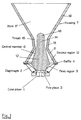
- Figure 2 is a vertical cross-sectional view of the loudspeaker of Figure 1;
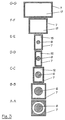
- Figure 3 shows transverse cross-sections taken at different points along the direction of propagation as illustrated in Figure 2; and
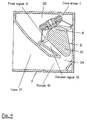
- Figure 4 is a horizontal cross-sectional view of a loudspeaker constituting a second embodiment of the invention.
-
- Like reference numerals refer to like parts throughout the drawings.
- The loudspeaker shown in Figures 1 to 3 is for use at upper bass/low mid frequencies, for example as part of a loudspeaker system of a PA system. The loudspeaker comprises a
cone driver 1. Thedriver 1 comprises aconical diaphragm 2 and a magnet structure with acentral pole piece 3. The front of the driver chassis is mounted on abaffle 4 and an enclosure illustrated diagrammatically at 5 in Figure 2 is disposed behind thedriver 1 and attached to thebaffle 4 so as to form a sealed chamber behind thedriver 1. - The loudspeaker comprises a
central member 6 andhousing 7 which define a channel for propagation of sound from the front of thediaphragm 2 to the exterior of thehousing 7. Thecentral member 6 is of circular transverse cross-section throughout its length and is attached at its rear to thepole piece 3. Thecentral member 6 has afirst portion 8 which extends into the conical volume defined by thediaphragm 2. Thefirst portion 8 and thediaphragm 2 define afirst region 9 of the channel of annular transverse cross-sectional shape. The transverse cross-sectional area of thefirst region 9 increases in the direction of sound propagation within the channel i.e. from thepole piece 3 approximately to the plane of thebaffle 4. Similarly, the transverse cross-sectional area of thefirst portion 8 increases in the direction of sound propagation. - The
central member 6 has asecond portion 10 whose transverse cross-sectional area decreases in the direction of sound propagation. Thesecond portion 10 is disposed centrally inside afirst portion 11 of thehousing 7 and defines therewith a ring-shapedsecond region 12 of the channel whose transverse cross-sectional area decreases in the direction of sound propagation. - The
housing 7 has asecond portion 13 which cooperates with athird portion 14 of thecentral member 6 to define athroat 15 which extends from thesecond region 12. Thehousing 7 has athird portion 16 which defines ahorn 17 extending from thethroat 15. Thecentral member 6 has afourth portion 18 of substantially hemispherical shape which projects into the start of thehorn 17. - The
central member 6 is circularly symmetrical about the longitudinal axis of the loudspeaker (coaxial with the direction of sound propagation within the channel). Thus, the transverse cross-sectional shape of thecentral member 6 is circular throughout its length. - The
throat 15 has a transverse cross-sectional area which increases at a first rate in the direction of propagation. Thehorn 17 has a transverse cross-sectional area which increases, in the direction of propagation, at a second rate which is greater than the first rate. The transverse cross-sectional area of thethird portion 14 of thecentral member 6 is substantially constant throughout thethroat 15 or most thereof . - As shown in Figure 2, the
housing 7 comprises upper andlower surfaces horn 17. The varying circular cross-section of thecentral member 6 is clearly shown in cross-sections A-A to E-E. Forward of thebaffle 10, thehousing 7 is of rectangular cross-section with the width varying throughout the length of the loudspeaker but with the height being substantially constant. The channel is therefore ring-shaped in transverse section throughout its length to the end of the hemisphericalfourth portion 18 of thecentral member 6. - A loudspeaker of the type shown in Figures 1 to 3 is capable of operating over approximately a decade from about 75 to about 750Hz. Although the mechanism is not fully understood, it is believed that a function of the
central member 6 is to maintain coherence in the upper part of the frequency spectrum of the loudspeaker and to move upwardly the whole frequency band of which the loudspeaker would be capable in the absence of thecentral member 6. It is also believed that the "constriction" which occurs in thesecond region 12 just before thethroat 15 compensates for the loss of low frequencies caused by thecentral member 6 by lowering the low frequency cut-off-point of the loudspeaker, it is believed that, typically in the absence of the constriction, the lower end of the frequency range would be about 150 to 200Hz. However, the presence of the constriction lowers this to about 75Hz. The combined effect is to provide a loudspeaker having excellent coherence across a large frequency band. - The loudspeaker provides very high output levels with high electro-acoustic efficiency, typically giving an acoustic output of 107 dB at one metre for an electrical input of one watt. Also, a wide and uniform dispersion pattern in the horizontal plane can be provided, as is typically required of PA systems. The loudspeaker has a smooth frequency response within its operating range and a fast transient response. All of these features make the loudspeaker suitable for use in very high quality PA systems.
- The loudspeaker shown in Figure 1 has an essentially straight acoustic channel within which the sound propagates from the
diaphragm 2 to the exterior. Such a loudspeaker occupies a substantial area in the horizontal plane. However, as shown in Figure 4, it is possible to provide a more compact loudspeaker of a type similar to that in Figure 1 by folding the channel. - The loudspeaker shown in Figure 4 differs from that shown in Figure 1 in two essential ways. The acoustic channel is bent around a vertical axis at or near the
transition 24 between thesecond region 12 and thethroat 15. Also, thecentral member 6 comprises only the first andsecond portions - The height of the
housing 7 is substantially constant and the whole loudspeaker is contained between parallel upper and lower walls. Thus, the loudspeaker shown in Figure 4 is acoustically similar to that shown in Figure 1 but occupies substantially less space. - Figure 4 also illustrates the sealed
chamber 25 acting as an enclosure behind thedriver 1.
Claims (14)
- An upper bass/low mid loudspeaker comprising: an electro-acoustic driver (1) having a conical diaphragm (2); and a housing (7) and a central member (6) defining a channel for the propagation of sound from the front of the diaphragm (2), characterised in that the central member (6) has a first portion (8) extending into the volume defined by the diaphragm (2) and defining with the diaphragm (2) a first region (9)of the channel of ring-shaped cross-section whose transverse cross-sectional area increases in the direction of sound propagation within the channel, the central member (6) having a second portion (10) disposed within a first portion (11) of the housing (7) to define a second region (12) of the channel of ring-shaped cross-section whose transverse cross-sectional area decreases in the direction of sound propagation within the channel, the housing (7) having a second portion (13) defining a throat (15) extending from the second region (12) and a third portion (16) defining a horn (17) extending from the throat (15).
- A loudspeaker as claimed in claim 1, characterised in that the first portion (11) of the central member (6) has a transverse cross-sectional area which increases in the direction of sound propagation within the channel and the second portion (10) of the central member (6) has a transverse cross-sectional area which decreases in the direction of sound propagation within the channel.
- A loudspeaker as claimed in claim 1 or 2, characterised in that the throat (15) has a transverse cross-sectional area which increases at a first rate in the direction of sound propagation within the channel.
- A loudspeaker as claimed in claim 3, characterised in that the horn (15) has a transverse cross-sectional area which increases at a second rate greater than the first rate in the direction of sound propagation within the channel.
- A loudspeaker as claimed in any one of the preceding claims, characterised in that the central member (6) has a third portion (14) extending within the second portion (13) of the housing (7) and defining therebetween the throat (15) which is of ring-shaped transverse cross-section.
- A loudspeaker as claimed in claim 5, characterised in that the central member (6) has a fourth portion (18) extending into the horn (17).
- A loudspeaker as claimed in claim 6, characterised in that the fourth portion (18) of the central member (6) has a substantially hemispherical end.
- A loudspeaker as claimed in any one of the preceding claims, characterised in that the central member (6) has a substantially circular transverse cross-sectional shape throughout its extent in the direction of sound propagation within the channel.
- A loudspeaker as claimed in any one of the preceding claims, characterised in that the housing (7) has a substantially rectangular transverse cross-sectional shape throughout its extent in the direction of sound propagation within the channel.
- A loudspeaker as claimed in any one of the preceding claims, characterised in that the housing (7) has a substantially parallel pair of internal surfaces.
- A loudspeaker as claimed in any one of the preceding claims, characterised in that the channel is folded.
- A loudspeaker as claimed in claim 11, characterised in that the channel is folded at or adjacent the transition between the second region (12) and the throat (15).
- A loudspeaker as claimed in any one of the preceding claims, characterised by an enclosure (5, 25) at the rear of the driver (1) forming therewith a substantially sealed chamber.
- A PA system characterised by a loudspeaker as claimed in any one of the preceding claims.
Applications Claiming Priority (2)
| Application Number | Priority Date | Filing Date | Title |
|---|---|---|---|
| GB9916380 | 1999-07-14 | ||
| GBGB9916380.0A GB9916380D0 (en) | 1999-07-14 | 1999-07-14 | Loudspeaker |
Publications (3)
| Publication Number | Publication Date |
|---|---|
| EP1069803A2 true EP1069803A2 (en) | 2001-01-17 |
| EP1069803A3 EP1069803A3 (en) | 2003-04-02 |
| EP1069803B1 EP1069803B1 (en) | 2009-11-04 |
Family
ID=10857146
Family Applications (1)
| Application Number | Title | Priority Date | Filing Date |
|---|---|---|---|
| EP00305298A Expired - Lifetime EP1069803B1 (en) | 1999-07-14 | 2000-06-23 | Loudspeaker |
Country Status (6)
| Country | Link |
|---|---|
| US (1) | US6650760B1 (en) |
| EP (1) | EP1069803B1 (en) |
| AT (1) | ATE447831T1 (en) |
| DE (1) | DE60043248D1 (en) |
| ES (1) | ES2333398T3 (en) |
| GB (1) | GB9916380D0 (en) |
Cited By (2)
| Publication number | Priority date | Publication date | Assignee | Title |
|---|---|---|---|---|
| FR2828784A1 (en) * | 2001-08-17 | 2003-02-21 | Etienne Bardier | Loudspeaker homogeneous bass sound transmission having guide tube axially placed loudspeaker membrane with surface around tube with structure enclosure held. |
| JP2021078097A (en) * | 2019-11-08 | 2021-05-20 | ヒュン・チュル・キム | Superdirective speaker |
Families Citing this family (5)
| Publication number | Priority date | Publication date | Assignee | Title |
|---|---|---|---|---|
| US7319772B2 (en) * | 2005-01-07 | 2008-01-15 | George Chang | Speaker device for improving mid/high-range frequencies |
| US8887862B2 (en) * | 2013-03-15 | 2014-11-18 | Bag End, Inc. | Phase plug device |
| CN109151658A (en) * | 2018-11-23 | 2019-01-04 | 江门波威音响器材有限公司 | A kind of phase plug and its speaker |
| CN109246503A (en) * | 2018-11-23 | 2019-01-18 | 江门波威音响器材有限公司 | A kind of Loudspeaker panel structure and its speaker |
| US11910174B1 (en) | 2023-03-31 | 2024-02-20 | Alexander Faraone | Radially arcuated unistructural speaker cone with segmented dome |
Citations (2)
| Publication number | Priority date | Publication date | Assignee | Title |
|---|---|---|---|---|
| US4181193A (en) | 1976-09-23 | 1980-01-01 | Isaac Timothy P | Sound projection system |
| GB2270606A (en) | 1992-09-15 | 1994-03-16 | Anthony John Andrews | Loudspeaker with radially asymmetric "phase plug" |
Family Cites Families (20)
| Publication number | Priority date | Publication date | Assignee | Title |
|---|---|---|---|---|
| US1485348A (en) * | 1922-06-15 | 1924-02-26 | Correl W Johnson | Sound clarifier |
| US2836664A (en) * | 1953-01-12 | 1958-05-27 | Gen Dynamics Corp | Loudspeaker |
| US2761913A (en) * | 1953-02-18 | 1956-09-04 | Gen Dynamics Corp | Loudspeaker |
| GB765184A (en) * | 1954-01-05 | 1957-01-02 | Donald Maynard Chave | Improvements in or relating to loudspeakers |
| US4091891A (en) * | 1973-01-17 | 1978-05-30 | Onkyo Kabushiki Kaisha | Horn speaker |
| USRE32183E (en) * | 1976-09-23 | 1986-06-17 | Turbosound Group Ltd. | Sound projection system |
| US4157741A (en) * | 1978-08-16 | 1979-06-12 | Goldwater Alan J | Phase plug |
| US4310065A (en) * | 1979-05-11 | 1982-01-12 | Chromalloy Electronics Corporation | Radial horn |
| JPS57136896A (en) * | 1981-02-18 | 1982-08-24 | Ibuki Kogyo Kk | Horn speaker |
| US4390078A (en) * | 1982-02-23 | 1983-06-28 | Community Light & Sound, Inc. | Loudspeaker horn |
| US4836327A (en) * | 1986-11-12 | 1989-06-06 | Turbosound Limited | Sound reinforcement enclosure employing cone loudspeaker with annular central loading member and coaxially mounted compression driver |
| GB8724299D0 (en) * | 1987-10-16 | 1987-11-18 | Adamson Acoustic Design Corp | Loudspeaker design |
| US4776428A (en) * | 1987-11-16 | 1988-10-11 | Belisle Acoustique Inc. | Sound projection system |
| FR2627886B1 (en) * | 1988-02-29 | 1994-05-13 | Heil Christian | CYLINDRICAL SOUND WAVE GUIDE |
| WO1994019915A1 (en) * | 1993-02-25 | 1994-09-01 | Heinz Ralph D | Multiple-driver single horn loudspeaker |
| US5900593A (en) * | 1995-07-31 | 1999-05-04 | Adamson; Alan Brock | Loudspeaker system |
| US5991421A (en) * | 1997-11-10 | 1999-11-23 | Single Source Technology And Development, Inc. | Radially expanding multiple flat-surfaced waveguide device |
| US6094495A (en) * | 1998-09-24 | 2000-07-25 | Eastern Acoustic Works, Inc. | Horn-type loudspeaker system |
| US6026928A (en) * | 1999-04-06 | 2000-02-22 | Maharaj; Ashok A. | Apparatus and method for reduced distortion loudspeakers |
| US6343133B1 (en) * | 1999-07-22 | 2002-01-29 | Alan Brock Adamson | Axially propagating mid and high frequency loudspeaker systems |
-
1999
- 1999-07-14 GB GBGB9916380.0A patent/GB9916380D0/en not_active Ceased
-
2000
- 2000-06-23 AT AT00305298T patent/ATE447831T1/en not_active IP Right Cessation
- 2000-06-23 EP EP00305298A patent/EP1069803B1/en not_active Expired - Lifetime
- 2000-06-23 ES ES00305298T patent/ES2333398T3/en not_active Expired - Lifetime
- 2000-06-23 DE DE60043248T patent/DE60043248D1/en not_active Expired - Lifetime
- 2000-06-30 US US09/607,393 patent/US6650760B1/en not_active Expired - Lifetime
Patent Citations (2)
| Publication number | Priority date | Publication date | Assignee | Title |
|---|---|---|---|---|
| US4181193A (en) | 1976-09-23 | 1980-01-01 | Isaac Timothy P | Sound projection system |
| GB2270606A (en) | 1992-09-15 | 1994-03-16 | Anthony John Andrews | Loudspeaker with radially asymmetric "phase plug" |
Cited By (2)
| Publication number | Priority date | Publication date | Assignee | Title |
|---|---|---|---|---|
| FR2828784A1 (en) * | 2001-08-17 | 2003-02-21 | Etienne Bardier | Loudspeaker homogeneous bass sound transmission having guide tube axially placed loudspeaker membrane with surface around tube with structure enclosure held. |
| JP2021078097A (en) * | 2019-11-08 | 2021-05-20 | ヒュン・チュル・キム | Superdirective speaker |
Also Published As
| Publication number | Publication date |
|---|---|
| GB9916380D0 (en) | 1999-09-15 |
| EP1069803B1 (en) | 2009-11-04 |
| DE60043248D1 (en) | 2009-12-17 |
| ATE447831T1 (en) | 2009-11-15 |
| EP1069803A3 (en) | 2003-04-02 |
| ES2333398T3 (en) | 2010-02-22 |
| US6650760B1 (en) | 2003-11-18 |
| HK1030512A1 (en) | 2001-05-04 |
Similar Documents
| Publication | Publication Date | Title |
|---|---|---|
| JP3410206B2 (en) | Speaker device | |
| AU2005244853B2 (en) | Closed loop embedded audio transmission line technology | |
| EP3413582B1 (en) | Headphone | |
| US20080029335A1 (en) | Sound Enhancement Module | |
| GB2184323A (en) | Loudspeaker system | |
| JP2001078288A (en) | Loudspeaker box | |
| EP0390165B1 (en) | Speaker system | |
| US20050175208A1 (en) | Audio speaker system employing an annular gasket separating a horn waveguide from a sound reproducing membrane | |
| EP1069803B1 (en) | Loudspeaker | |
| US7093688B2 (en) | Structure for preventing the generation of standing waves and a method for implementing the same | |
| US7418104B2 (en) | Speaker system | |
| KR101539064B1 (en) | Earphone having multi-echo spaces | |
| CN112423206B (en) | Coaxial loudspeaker | |
| US6721431B1 (en) | Prismatic loudspeaker/microphone array | |
| KR100312000B1 (en) | speaker | |
| HK1030512B (en) | Loudspeaker | |
| US6870942B1 (en) | Loudspeaker for line array sound system | |
| JP2884576B2 (en) | Speaker system | |
| KR102020233B1 (en) | Multi-driver earphone | |
| JP2776542B2 (en) | Speaker system | |
| JP2556213B2 (en) | Speaker system | |
| CN210298019U (en) | In-ear earphone | |
| GB2391739A (en) | Speaker enclosure attenuates rear waves through destructive interference of the divided and then recombined wavefront | |
| JPH01272296A (en) | speaker system | |
| AU738580B1 (en) | Loudspeaker enclosure system |
Legal Events
| Date | Code | Title | Description |
|---|---|---|---|
| PUAI | Public reference made under article 153(3) epc to a published international application that has entered the european phase |
Free format text: ORIGINAL CODE: 0009012 |
|
| AK | Designated contracting states |
Kind code of ref document: A2 Designated state(s): AT BE CH CY DE DK ES FI FR GB GR IE IT LI LU MC NL PT SE |
|
| AX | Request for extension of the european patent |
Free format text: AL;LT;LV;MK;RO;SI |
|
| PUAL | Search report despatched |
Free format text: ORIGINAL CODE: 0009013 |
|
| AK | Designated contracting states |
Kind code of ref document: A3 Designated state(s): AT BE CH CY DE DK ES FI FR GB GR IE IT LI LU MC NL PT SE |
|
| AX | Request for extension of the european patent |
Extension state: AL LT LV MK RO SI |
|
| 17P | Request for examination filed |
Effective date: 20030908 |
|
| AKX | Designation fees paid |
Designated state(s): AT BE CH CY DE DK ES FI FR GB GR IE IT LI LU MC NL PT SE |
|
| 17Q | First examination report despatched |
Effective date: 20070612 |
|
| GRAP | Despatch of communication of intention to grant a patent |
Free format text: ORIGINAL CODE: EPIDOSNIGR1 |
|
| GRAS | Grant fee paid |
Free format text: ORIGINAL CODE: EPIDOSNIGR3 |
|
| GRAA | (expected) grant |
Free format text: ORIGINAL CODE: 0009210 |
|
| AK | Designated contracting states |
Kind code of ref document: B1 Designated state(s): AT BE CH CY DE DK ES FI FR GB GR IE IT LI LU MC NL PT SE |
|
| REG | Reference to a national code |
Ref country code: GB Ref legal event code: FG4D |
|
| REG | Reference to a national code |
Ref country code: CH Ref legal event code: EP |
|
| REG | Reference to a national code |
Ref country code: IE Ref legal event code: FG4D |
|
| REF | Corresponds to: |
Ref document number: 60043248 Country of ref document: DE Date of ref document: 20091217 Kind code of ref document: P |
|
| REG | Reference to a national code |
Ref country code: ES Ref legal event code: FG2A Ref document number: 2333398 Country of ref document: ES Kind code of ref document: T3 |
|
| NLV1 | Nl: lapsed or annulled due to failure to fulfill the requirements of art. 29p and 29m of the patents act | ||
| PG25 | Lapsed in a contracting state [announced via postgrant information from national office to epo] |
Ref country code: SE Free format text: LAPSE BECAUSE OF FAILURE TO SUBMIT A TRANSLATION OF THE DESCRIPTION OR TO PAY THE FEE WITHIN THE PRESCRIBED TIME-LIMIT Effective date: 20091104 Ref country code: PT Free format text: LAPSE BECAUSE OF FAILURE TO SUBMIT A TRANSLATION OF THE DESCRIPTION OR TO PAY THE FEE WITHIN THE PRESCRIBED TIME-LIMIT Effective date: 20100304 Ref country code: FI Free format text: LAPSE BECAUSE OF FAILURE TO SUBMIT A TRANSLATION OF THE DESCRIPTION OR TO PAY THE FEE WITHIN THE PRESCRIBED TIME-LIMIT Effective date: 20091104 |
|
| PG25 | Lapsed in a contracting state [announced via postgrant information from national office to epo] |
Ref country code: CY Free format text: LAPSE BECAUSE OF FAILURE TO SUBMIT A TRANSLATION OF THE DESCRIPTION OR TO PAY THE FEE WITHIN THE PRESCRIBED TIME-LIMIT Effective date: 20091104 |
|
| REG | Reference to a national code |
Ref country code: HK Ref legal event code: GR Ref document number: 1030512 Country of ref document: HK |
|
| PG25 | Lapsed in a contracting state [announced via postgrant information from national office to epo] |
Ref country code: BE Free format text: LAPSE BECAUSE OF FAILURE TO SUBMIT A TRANSLATION OF THE DESCRIPTION OR TO PAY THE FEE WITHIN THE PRESCRIBED TIME-LIMIT Effective date: 20091104 Ref country code: AT Free format text: LAPSE BECAUSE OF FAILURE TO SUBMIT A TRANSLATION OF THE DESCRIPTION OR TO PAY THE FEE WITHIN THE PRESCRIBED TIME-LIMIT Effective date: 20091104 |
|
| PG25 | Lapsed in a contracting state [announced via postgrant information from national office to epo] |
Ref country code: DK Free format text: LAPSE BECAUSE OF FAILURE TO SUBMIT A TRANSLATION OF THE DESCRIPTION OR TO PAY THE FEE WITHIN THE PRESCRIBED TIME-LIMIT Effective date: 20091104 |
|
| PLBE | No opposition filed within time limit |
Free format text: ORIGINAL CODE: 0009261 |
|
| STAA | Information on the status of an ep patent application or granted ep patent |
Free format text: STATUS: NO OPPOSITION FILED WITHIN TIME LIMIT |
|
| 26N | No opposition filed |
Effective date: 20100805 |
|
| PG25 | Lapsed in a contracting state [announced via postgrant information from national office to epo] |
Ref country code: GR Free format text: LAPSE BECAUSE OF FAILURE TO SUBMIT A TRANSLATION OF THE DESCRIPTION OR TO PAY THE FEE WITHIN THE PRESCRIBED TIME-LIMIT Effective date: 20100205 |
|
| PG25 | Lapsed in a contracting state [announced via postgrant information from national office to epo] |
Ref country code: MC Free format text: LAPSE BECAUSE OF NON-PAYMENT OF DUE FEES Effective date: 20100630 |
|
| REG | Reference to a national code |
Ref country code: CH Ref legal event code: PL |
|
| PG25 | Lapsed in a contracting state [announced via postgrant information from national office to epo] |
Ref country code: LI Free format text: LAPSE BECAUSE OF NON-PAYMENT OF DUE FEES Effective date: 20100630 Ref country code: CH Free format text: LAPSE BECAUSE OF NON-PAYMENT OF DUE FEES Effective date: 20100630 Ref country code: IE Free format text: LAPSE BECAUSE OF NON-PAYMENT OF DUE FEES Effective date: 20100623 |
|
| PG25 | Lapsed in a contracting state [announced via postgrant information from national office to epo] |
Ref country code: NL Free format text: LAPSE BECAUSE OF FAILURE TO SUBMIT A TRANSLATION OF THE DESCRIPTION OR TO PAY THE FEE WITHIN THE PRESCRIBED TIME-LIMIT Effective date: 20091104 Ref country code: LU Free format text: LAPSE BECAUSE OF NON-PAYMENT OF DUE FEES Effective date: 20100623 |
|
| REG | Reference to a national code |
Ref country code: FR Ref legal event code: PLFP Year of fee payment: 17 |
|
| REG | Reference to a national code |
Ref country code: FR Ref legal event code: PLFP Year of fee payment: 18 |
|
| REG | Reference to a national code |
Ref country code: FR Ref legal event code: PLFP Year of fee payment: 19 |
|
| PGFP | Annual fee paid to national office [announced via postgrant information from national office to epo] |
Ref country code: DE Payment date: 20180612 Year of fee payment: 19 |
|
| PGFP | Annual fee paid to national office [announced via postgrant information from national office to epo] |
Ref country code: FR Payment date: 20180511 Year of fee payment: 19 |
|
| PGFP | Annual fee paid to national office [announced via postgrant information from national office to epo] |
Ref country code: IT Payment date: 20180625 Year of fee payment: 19 Ref country code: GB Payment date: 20180403 Year of fee payment: 19 Ref country code: ES Payment date: 20180702 Year of fee payment: 19 |
|
| REG | Reference to a national code |
Ref country code: DE Ref legal event code: R119 Ref document number: 60043248 Country of ref document: DE |
|
| GBPC | Gb: european patent ceased through non-payment of renewal fee |
Effective date: 20190623 |
|
| PG25 | Lapsed in a contracting state [announced via postgrant information from national office to epo] |
Ref country code: GB Free format text: LAPSE BECAUSE OF NON-PAYMENT OF DUE FEES Effective date: 20190623 Ref country code: DE Free format text: LAPSE BECAUSE OF NON-PAYMENT OF DUE FEES Effective date: 20200101 Ref country code: IT Free format text: LAPSE BECAUSE OF NON-PAYMENT OF DUE FEES Effective date: 20190623 |
|
| PG25 | Lapsed in a contracting state [announced via postgrant information from national office to epo] |
Ref country code: FR Free format text: LAPSE BECAUSE OF NON-PAYMENT OF DUE FEES Effective date: 20190630 |
|
| REG | Reference to a national code |
Ref country code: ES Ref legal event code: FD2A Effective date: 20201029 |
|
| PG25 | Lapsed in a contracting state [announced via postgrant information from national office to epo] |
Ref country code: ES Free format text: LAPSE BECAUSE OF NON-PAYMENT OF DUE FEES Effective date: 20190624 |