EP1069790B1 - Method and apparatus for dynamically assigning channel in asynchronous mobile communication system - Google Patents
Method and apparatus for dynamically assigning channel in asynchronous mobile communication system Download PDFInfo
- Publication number
- EP1069790B1 EP1069790B1 EP20000305798 EP00305798A EP1069790B1 EP 1069790 B1 EP1069790 B1 EP 1069790B1 EP 20000305798 EP20000305798 EP 20000305798 EP 00305798 A EP00305798 A EP 00305798A EP 1069790 B1 EP1069790 B1 EP 1069790B1
- Authority
- EP
- European Patent Office
- Prior art keywords
- data packets
- mobile station
- transport channel
- traffic volume
- predetermined value
- Prior art date
- Legal status (The legal status is an assumption and is not a legal conclusion. Google has not performed a legal analysis and makes no representation as to the accuracy of the status listed.)
- Expired - Lifetime
Links
- 238000000034 method Methods 0.000 title claims description 22
- 238000010295 mobile communication Methods 0.000 title claims description 18
- 230000005540 biological transmission Effects 0.000 claims description 9
- 230000032258 transport Effects 0.000 description 53
- 238000010586 diagram Methods 0.000 description 18
- 230000008569 process Effects 0.000 description 5
- 230000011664 signaling Effects 0.000 description 4
- 108010003272 Hyaluronate lyase Proteins 0.000 description 3
- 238000004891 communication Methods 0.000 description 3
- 238000012546 transfer Methods 0.000 description 3
- 230000003247 decreasing effect Effects 0.000 description 2
- 230000009467 reduction Effects 0.000 description 2
- 238000007792 addition Methods 0.000 description 1
- 238000012937 correction Methods 0.000 description 1
- 230000003111 delayed effect Effects 0.000 description 1
- 238000001514 detection method Methods 0.000 description 1
- 238000013507 mapping Methods 0.000 description 1
- 238000012986 modification Methods 0.000 description 1
- 230000004048 modification Effects 0.000 description 1
- 238000012544 monitoring process Methods 0.000 description 1
- 238000006467 substitution reaction Methods 0.000 description 1
Images


Classifications
-
- H—ELECTRICITY
- H04—ELECTRIC COMMUNICATION TECHNIQUE
- H04W—WIRELESS COMMUNICATION NETWORKS
- H04W72/00—Local resource management
- H04W72/20—Control channels or signalling for resource management
- H04W72/23—Control channels or signalling for resource management in the downlink direction of a wireless link, i.e. towards a terminal
-
- H—ELECTRICITY
- H04—ELECTRIC COMMUNICATION TECHNIQUE
- H04W—WIRELESS COMMUNICATION NETWORKS
- H04W72/00—Local resource management
- H04W72/50—Allocation or scheduling criteria for wireless resources
- H04W72/52—Allocation or scheduling criteria for wireless resources based on load
-
- H—ELECTRICITY
- H04—ELECTRIC COMMUNICATION TECHNIQUE
- H04W—WIRELESS COMMUNICATION NETWORKS
- H04W72/00—Local resource management
- H04W72/50—Allocation or scheduling criteria for wireless resources
- H04W72/54—Allocation or scheduling criteria for wireless resources based on quality criteria
- H04W72/542—Allocation or scheduling criteria for wireless resources based on quality criteria using measured or perceived quality
-
- H—ELECTRICITY
- H04—ELECTRIC COMMUNICATION TECHNIQUE
- H04W—WIRELESS COMMUNICATION NETWORKS
- H04W24/00—Supervisory, monitoring or testing arrangements
- H04W24/10—Scheduling measurement reports ; Arrangements for measurement reports
-
- H—ELECTRICITY
- H04—ELECTRIC COMMUNICATION TECHNIQUE
- H04W—WIRELESS COMMUNICATION NETWORKS
- H04W72/00—Local resource management
- H04W72/12—Wireless traffic scheduling
-
- H—ELECTRICITY
- H04—ELECTRIC COMMUNICATION TECHNIQUE
- H04W—WIRELESS COMMUNICATION NETWORKS
- H04W72/00—Local resource management
- H04W72/50—Allocation or scheduling criteria for wireless resources
- H04W72/51—Allocation or scheduling criteria for wireless resources based on terminal or device properties
-
- H—ELECTRICITY
- H04—ELECTRIC COMMUNICATION TECHNIQUE
- H04W—WIRELESS COMMUNICATION NETWORKS
- H04W72/00—Local resource management
- H04W72/50—Allocation or scheduling criteria for wireless resources
- H04W72/56—Allocation or scheduling criteria for wireless resources based on priority criteria
- H04W72/563—Allocation or scheduling criteria for wireless resources based on priority criteria of the wireless resources
Definitions
- the present invention relates to a method and apparatus for assigning a channel in a mobile communication system; more particularly, relates to a method and apparatus for dynamically assigning a channel in an asynchronous mobile communication system when transmitting radio data packets from a base station to a mobile station (as is referred to "downlink").
- Fig. 1 is a block diagram of a channel assigning device in a conventional mobile communication system.
- the mobile communication system includes a mobile station 10, a radio access network controller 20, a base transceiver station 30 and a mobile switching center 40.
- the mobile station 10 includes a layer 1, a layer 2 and a layer 3.
- the layer 3 includes a call control/mobility management (CC/MM) entity 12 and a radio resource control (RRC) layer 14.
- the layer 2 includes a radio link control (RLC) layer and a medium access control (MAC) layer.
- the layer 1 includes physical layer 16 having a channel element 18. In substantial, the call control entity 12, the radio resource control layer 14 and the channel element 18 assigns a channel for transmitting signal.
- the radio access network controller 20 includes a physical layer, a MAC layer, a RLC layer, a RRC layer 24 and a CC/MM entity 22.
- the base transceiver station 30 includes a physical layer having a channel element 32.
- the mobile switching center 40 includes a physical layer, a MAC layer, a RLC layer, a RRC layer and a CC/MM entity 42.
- a downlink shared channel (DSCH) is used when transmitting radio data packets from a base station to a mobile station in an asynchronous mobile communication system.
- a common packet channel (CPCH) is used when transmitting radio data packets from a mobile station to a base station in an asynchronous mobile communication system.
- the DSCH transport channel and the CPCH transport channel are assigned in the RRC layer of the UTRAN.
- Each channel configuration is performed in the RRC layer.
- the channel configuration means that channel information elements, for example, a scrambling code, a spreading factor and a data rate of the assigned channel, are selected.
- Fig. 2 is a diagram showing a conventional DSCH transport channel.
- the DSCH transport channel is shared by a plurality of the mobile stations when transmitting data packets from the UTRAN to the MS 10.
- Each of the mobile stations has different quality of service, data rate and traffic volume.
- the data rate means an amount of transmitted data per a second.
- a mean data rate and a maximum data rate are specified before call setup.
- the traffic volume means an amount of data transmitted through a channel or a buffer for a predetermined period.
- the traffic volume is described with respect to data transmission capacity of the channel or the buffer.
- a conventional mobile communication system uses a spreading factor reduction method.
- reduction of the spreading factor increases transmission power (about twice). Increased transmission power acts as interference to signals for the neighbor mobile stations, to thereby fall quality of communication service.
- Fig. 3A is a diagram of protocol layers of a mobile communication system having a volume detector in accordance with the present invention.
- the mobile communication system has similar functions as those of mobile communication system in Fig. 1 except that the system has a volume detector. Accordingly, it is assumed that the same reference numeral denotes the same function block.
- the physical layer 16 offers data transport services to higher layers and transfers transport blocks over a radio interface to a mobile station.
- the channel element 18 performs functions for data transmission, e.g., encoding, modulation and interleaving of data to be transmitted.
- the MAC layer offers data transfer services on logical channels to a higher layer (RLC layer) and on transport channels to a lower layer (the physical layer).
- the MAC layer is responsible for mapping of the logical channel onto the appropriate transports channel.
- the RLC layer offers data transfer services on primitive to a higher layer and on logical channels to a lower layer (MAC layer). Also, the RLC layer performs an error correction process, a duplicate detection process, a ciphering process and a flow control process of the data.
- the RRC layer 14 offers data transmission services on primitive to a lower layer (RLC layer) and handles a control plane signaling of the layer 3 between a user equipment (UE) and an asynchronous radio network.
- the RRC layer 14 manages a radio resource. Also, the RRC layer assigns/reconfigures/releases the radio resource to user equipment /Universal mobile telecommunication system Terrestrial Radio Access Network (UE/UTRAN).
- UE Universal mobile telecommunication system Terrestrial Radio Access Network
- the CC entity handles a call control signaling of layer 3 between the UEs and the asynchronous radio network.
- the MM entity handles a mobility management signaling of layer 3 between the UEs and the asynchronous radio network.
- the layers of the mobile station communicate with corresponding layers of UTRAN.
- the reference numeral 20 denotes a radio access network controller including a CC/MM entity 22, a RRC layer 24, a RLC layer, a MAC layer and a physical layer.
- Functions of the protocol layers are similar to those described above referring to those of the mobile station 10. Accordingly, for the sake of convenience, a detailed description on functions of the protocol layers will be skipped.
- the reference numeral 30 denotes a base transceiver station (BTS).
- the BTS 30 communicates data with the mobile station 10 through radio channels and includes a channel element.
- Functions of the protocol layers for a base station are similar to those described above referring to those of the mobile station 10. Accordingly, for the sake of convenience, a detailed description on functions of the protocol layers will be skipped.
- the reference numeral 40 denotes a mobile switching center. Functions of the protocol layers are similar to those described above referring to those of the mobile station 10. Accordingly, for the sake of convenience, a detailed description on functions of the protocol layers will be skipped.
- the mobile station 10 is not directly connected to the RNC 20, the mobile station 10 is connected to the RNC 20 in Fig. 1 in order to show that role of the RNC 20 is more important for channel assignment than that of the BS 30. In substantial, the channel assignment is performed in UTRAN including the RNC 20 and the BS 30.
- the volume detector monitors data (e.g., control signaling data) from the RRC layer to the physical layer and data (e.g., packet data) from the RLC layer to the physical layer.
- data e.g., control signaling data
- data e.g., packet data
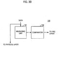
- Fig. 3B is a block diagram of the volume detector 100 of Fig. 3A.
- the volume detector 100 includes a measuring unit 102 and a comparator 104.
- the volume detector 100 monitors data packets to be transmitted to the mobile station and measures traffic volume of the data packets in a measuring unit 102.
- the measuring unit 102 sends the measured traffic volume of the data packets to a comparator 104.
- the comparator 104 compares the measured traffic volume of the data packets with predetermined values and transmits the comparing result to the RRC layer.
- Fig. 4A is a diagram of volume detectors where each volume detector measures traffic volume of data for each user and to be inputted to DSCH transport channel.
- volume detectors 51 to 50+N there are the same number of volume detectors 51 to 50+N as that of mobile stations connected to the UTRAN.
- Each volume detector measures traffic volume of data for each mobile station and to be inputted to DSCH transport channel.
- Fig. 4B is a diagram of a volume detector which measures traffic volume of data for a certain user and to be inputted to DCH transport channel.
- Input parameters for the volume detector monitoring the traffic volume of the data to inputted to the DSCH and DCH transport channels are as follows:
- the volume detector obtains these parameters from a call admission controller (CAC)(not shown in the drawing) in a radio resource management (RRM) unit of the RRC layer. Dynamic channel assignment and channel switching are performed in accordance with measuring results of the volume detector.
- CAC call admission controller
- RRM radio resource management
- Fig. 5 is a flow chart illustrating a method for assigning a channel in accordance with one embodiment of the present invention.
- parameters for the traffic volume detector which are described above, are set and stored on a memory device in the traffic volume detector at step S11.
- the volume detector measures traffic volume of data to be inputted into the DSCH transport channel for a predetermined time at step S12. Also, the volume detector monitors whether the data to be inputted to the transport channel has characteristics of the traffic descriptor set at step S11.
- step S13 it is determined whether the measured traffic volume is larger than a maximum buffer threshold U_limit. If the measured traffic volume is smaller than the maximum buffer threshold U_limit, the data is transmitted through only the assigned DSCH transport channel.
- a DCH transport channel is assigned to the mobile station.
- the data is transmitted through two transport channels multi-coded.
- the DCH transport channel is assigned to only a mobile station to receive data of which traffic volume is increased. In other words, only when the traffic volume of data for the mobile station is larger than the maximum buffer threshold U_limit, the DCH transport channel is assigned. At least one DCH transport channel can be simultaneously assigned to each user.
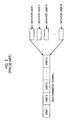
- Fig. 6 is an exemplary diagram of transport channels showing an assignment of a DCH transport channel because of increment of the traffic volume on DSCH transport channel.
- the data for a mobile station is transmitted through a DSCH transport channel as illustrated on the left side of Fig. 6.
- a DCH transport channel is additionally assigned to the mobile station as described on the right side of Fig. 6.
- Fig. 7 is a flow chart illustrating a method for assigning a channel in accordance with another embodiment of the present invention.
- parameters for the traffic volume detector e.g., the maximum buffer threshold U_limit, the minimum buffer threshold and the traffic descriptor.
- the volume detector measures traffic volume of data to be inputted into the DSCH transport channel for a predetermined time at step S22. Also, the volume detector monitors whether the data to be inputted to the DSCH transport channel has characteristics of the traffic descriptor set at step S21.
- step S23 it is determined whether the measured traffic volume of the data for a mobile station is larger than a maximum buffer threshold U_limit. If the measured traffic volume of the data for the mobile station is larger than the maximum buffer threshold U_limit, at step S24, an additional DSCH transport channel is assigned to the mobile station and the data is transmitted through the three transport channels, two DSCH and one DCH transport channels which are multi-coded.
- step S25 determines whether the traffic volume of the data is smaller than the minimum buffer threshold L_limit. If the traffic volume is smaller than the minimum buffer threshold L_limit, the assigned DCH transport channel is released and the data is transmitted through only the DSCH transport channel to the mobile station at step S26.
- the data is transmitted through one DSCH and one DCH transport channels which are already assigned.
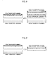
- Fig. 8 is an exemplary diagram showing an assignment of another DSCH transport channel because of increment of the traffic volume on DCH transport channel.
- the data for a mobile station is transmitted through a DSCH and a DCH transport channels as illustrated on the left side of Fig. 8.
- a DSCH transport channel is additionally assigned to the mobile station as described on the right side of Fig. 8.
- Fig. 9 is an exemplary diagram demonstrating a release of the DCH transport channel because of decrement of the traffic volume on DCH transport channel.
- the data for a mobile station is transmitted through a DSCH and a DCH transport channels as illustrated on the left side of Fig. 9.
- the traffic volume is decreased, in other words, is smaller than the minimum buffer threshold L_limit, the DCH transport channel is released and the data is transmitted through only the DSCH transport channel as described on the right side of Fig. 9.
- an additional DCH channel is assigned to a mobile station when traffic volume of data for the mobile station is increased and therefore channel switching happens.
- the dynamic channel assigning method prevents quality of service from falling without causing interference to the other mobile stations where the fall of quality of service results from increment of the traffic volume.
- the DCH transport channel is released when the traffic volume is decreased. This dynamic channel assignment makes the communication systems stable and efficient.
Landscapes
- Engineering & Computer Science (AREA)
- Computer Networks & Wireless Communication (AREA)
- Signal Processing (AREA)
- Quality & Reliability (AREA)
- Mobile Radio Communication Systems (AREA)
- Time-Division Multiplex Systems (AREA)
Description
- The present invention relates to a method and apparatus for assigning a channel in a mobile communication system; more particularly, relates to a method and apparatus for dynamically assigning a channel in an asynchronous mobile communication system when transmitting radio data packets from a base station to a mobile station (as is referred to "downlink").
- Fig. 1 is a block diagram of a channel assigning device in a conventional mobile communication system.
- The mobile communication system includes a
mobile station 10, a radioaccess network controller 20, abase transceiver station 30 and amobile switching center 40. - The
mobile station 10 includes a layer 1, a layer 2 and a layer 3. The layer 3 includes a call control/mobility management (CC/MM)entity 12 and a radio resource control (RRC)layer 14. The layer 2 includes a radio link control (RLC) layer and a medium access control (MAC) layer. The layer 1 includesphysical layer 16 having achannel element 18. In substantial, thecall control entity 12, the radioresource control layer 14 and thechannel element 18 assigns a channel for transmitting signal. - The radio
access network controller 20 includes a physical layer, a MAC layer, a RLC layer, aRRC layer 24 and a CC/MM entity 22. - The
base transceiver station 30 includes a physical layer having achannel element 32. - The
mobile switching center 40 includes a physical layer, a MAC layer, a RLC layer, a RRC layer and a CC/MM entity 42. - In general, a downlink shared channel (DSCH) is used when transmitting radio data packets from a base station to a mobile station in an asynchronous mobile communication system. A common packet channel (CPCH) is used when transmitting radio data packets from a mobile station to a base station in an asynchronous mobile communication system.
- The DSCH transport channel and the CPCH transport channel are assigned in the RRC layer of the UTRAN. Each channel configuration is performed in the RRC layer. The channel configuration means that channel information elements, for example, a scrambling code, a spreading factor and a data rate of the assigned channel, are selected.
- Fig. 2 is a diagram showing a conventional DSCH transport channel.
- Referring to Fig. 2, the DSCH transport channel is shared by a plurality of the mobile stations when transmitting data packets from the UTRAN to the
MS 10. Each of the mobile stations has different quality of service, data rate and traffic volume. - The data rate means an amount of transmitted data per a second. In general, a mean data rate and a maximum data rate are specified before call setup.
- The traffic volume means an amount of data transmitted through a channel or a buffer for a predetermined period. In other words, the traffic volume is described with respect to data transmission capacity of the channel or the buffer.
- When the DSCH transport channel is shared by a plurality of mobile stations, if the traffic volume of data for to one mobile station is increased, data inputted later are considerably delayed.
- In order to solve such problem, a conventional mobile communication system uses a spreading factor reduction method. However, reduction of the spreading factor increases transmission power (about twice). Increased transmission power acts as interference to signals for the neighbor mobile stations, to thereby fall quality of communication service.
- The paper entitled "FRAMES FMA 2 Wideband-CDMA for UMTS" by Toskala et al from European Transactions On Telecommunications, Eurel Publication, Milano, It (01-07-1998), 9(4),325-335 describes an asynchronous network communication structure which has a flexible layer 1 support for variable transmission requirements. The described system allows packet transmission to take place either on a common fixed rate transit channel or on a dedicated variable rate channel based upon packet traffic characteristics.
- Therefore, it is an aim of the present invention to provide a method and apparatus for dynamically assigning a channel in an asynchronous mobile communication system when transmitting radio data packets on downlink, thereby guaranteeing the quality of service for each user.
- In accordance with an aspect of the present invention, there is provided a method for operating an asynchronous mobile communication system as set out in claim 1.
- In accordance with another aspect of the present invention, there is provided an apparatus for operating an asynchronous mobile communication system as set out in claim 4.
- The above and other objects and features of the instant invention will become apparent from the following description of preferred embodiments taken in conjunction with the accompanying drawings, in which:
- Fig. 1 is a block diagram of a channel assigning device in a conventional mobile communication system;
- Fig. 2 is a diagram showing a conventional DSCH transport channel;
- Fig. 3A is a diagram of protocol layers of a mobile communication system having a volume detector in accordance with the present invention;
- Fig. 3B is a block diagram of the volume detector in accordance with the present invention;
- Fig. 4A is a diagram of volume detectors where each volume detector measures traffic volume of data for each user and to be inputted to DSCH transport channel;
- Fig. 4B is a diagram of a volume detector which measures traffic volume of data for a certain user and to be inputted to DCH transport channel.
- Fig. 5 is a flow chart illustrating a method for assigning a channel in accordance with one embodiment of the present invention;
- Fig. 6 is an exemplary diagram showing an assignment of a DCH transport channel because of increment of the traffic volume on DSCH transport channel;
- Fig. 7 is a flow chart illustrating a method for assigning a channel in accordance with another embodiment of the present invention;
- Fig. 8 is an exemplary diagram showing an assignment of another DSCH transport channel because of increment of the traffic volume on DCH transport channel; and
- Fig. 9 is an exemplary diagram demonstrating a release of the DCH transport channel because of decrement of the traffic volume on DCH transport channel.
- Hereinafter, preferred embodiments of the present invention will be described in detail with reference to the accompanying drawings.
- Fig. 3A is a diagram of protocol layers of a mobile communication system having a volume detector in accordance with the present invention.
- The mobile communication system has similar functions as those of mobile communication system in Fig. 1 except that the system has a volume detector. Accordingly, it is assumed that the same reference numeral denotes the same function block.
- The
physical layer 16 offers data transport services to higher layers and transfers transport blocks over a radio interface to a mobile station. Thechannel element 18 performs functions for data transmission, e.g., encoding, modulation and interleaving of data to be transmitted. - The MAC layer offers data transfer services on logical channels to a higher layer (RLC layer) and on transport channels to a lower layer (the physical layer). The MAC layer is responsible for mapping of the logical channel onto the appropriate transports channel.
- The RLC layer offers data transfer services on primitive to a higher layer and on logical channels to a lower layer (MAC layer). Also, the RLC layer performs an error correction process, a duplicate detection process, a ciphering process and a flow control process of the data.
- The
RRC layer 14 offers data transmission services on primitive to a lower layer (RLC layer) and handles a control plane signaling of the layer 3 between a user equipment (UE) and an asynchronous radio network. The RRClayer 14 manages a radio resource. Also, the RRC layer assigns/reconfigures/releases the radio resource to user equipment /Universal mobile telecommunication system Terrestrial Radio Access Network (UE/UTRAN). - The CC entity handles a call control signaling of layer 3 between the UEs and the asynchronous radio network.
- The MM entity handles a mobility management signaling of layer 3 between the UEs and the asynchronous radio network.
- The layers of the mobile station communicate with corresponding layers of UTRAN.
- The
reference numeral 20 denotes a radio access network controller including a CC/MM entity 22, aRRC layer 24, a RLC layer, a MAC layer and a physical layer. Functions of the protocol layers are similar to those described above referring to those of themobile station 10. Accordingly, for the sake of convenience, a detailed description on functions of the protocol layers will be skipped. - The
reference numeral 30 denotes a base transceiver station (BTS). TheBTS 30 communicates data with themobile station 10 through radio channels and includes a channel element. Functions of the protocol layers for a base station are similar to those described above referring to those of themobile station 10. Accordingly, for the sake of convenience, a detailed description on functions of the protocol layers will be skipped. - The
reference numeral 40 denotes a mobile switching center. Functions of the protocol layers are similar to those described above referring to those of themobile station 10. Accordingly, for the sake of convenience, a detailed description on functions of the protocol layers will be skipped. - Though the
mobile station 10 is not directly connected to theRNC 20, themobile station 10 is connected to theRNC 20 in Fig. 1 in order to show that role of theRNC 20 is more important for channel assignment than that of theBS 30. In substantial, the channel assignment is performed in UTRAN including theRNC 20 and theBS 30. - The volume detector monitors data (e.g., control signaling data) from the RRC layer to the physical layer and data (e.g., packet data) from the RLC layer to the physical layer.
- Fig. 3B is a block diagram of the
volume detector 100 of Fig. 3A. Thevolume detector 100 includes a measuringunit 102 and acomparator 104. - The
volume detector 100 monitors data packets to be transmitted to the mobile station and measures traffic volume of the data packets in ameasuring unit 102. The measuringunit 102 sends the measured traffic volume of the data packets to acomparator 104. Thecomparator 104 compares the measured traffic volume of the data packets with predetermined values and transmits the comparing result to the RRC layer. - Fig. 4A is a diagram of volume detectors where each volume detector measures traffic volume of data for each user and to be inputted to DSCH transport channel.
- Referring to Fig. 4A, there are the same number of
volume detectors 51 to 50+N as that of mobile stations connected to the UTRAN. Each volume detector measures traffic volume of data for each mobile station and to be inputted to DSCH transport channel. - Fig. 4B is a diagram of a volume detector which measures traffic volume of data for a certain user and to be inputted to DCH transport channel.
- Input parameters for the volume detector monitoring the traffic volume of the data to inputted to the DSCH and DCH transport channels are as follows:
- a) Maximum buffer threshold U_limit
- b) Minimum buffer threshold L_limit
- c) Traffic descriptor including peak rate, mean rate and packet delay variation.
- The volume detector obtains these parameters from a call admission controller (CAC)(not shown in the drawing) in a radio resource management (RRM) unit of the RRC layer. Dynamic channel assignment and channel switching are performed in accordance with measuring results of the volume detector.
- Fig. 5 is a flow chart illustrating a method for assigning a channel in accordance with one embodiment of the present invention.
- First, parameters for the traffic volume detector, which are described above, are set and stored on a memory device in the traffic volume detector at step S11. The volume detector measures traffic volume of data to be inputted into the DSCH transport channel for a predetermined time at step S12. Also, the volume detector monitors whether the data to be inputted to the transport channel has characteristics of the traffic descriptor set at step S11.
- At step S13, it is determined whether the measured traffic volume is larger than a maximum buffer threshold U_limit. If the measured traffic volume is smaller than the maximum buffer threshold U_limit, the data is transmitted through only the assigned DSCH transport channel.
- If the measured traffic volume of data for a mobile station is larger than the maximum buffer threshold U_limit, at step S14, a DCH transport channel is assigned to the mobile station. The data is transmitted through two transport channels multi-coded.
- The DCH transport channel is assigned to only a mobile station to receive data of which traffic volume is increased. In other words, only when the traffic volume of data for the mobile station is larger than the maximum buffer threshold U_limit, the DCH transport channel is assigned. At least one DCH transport channel can be simultaneously assigned to each user.
- Fig. 6 is an exemplary diagram of transport channels showing an assignment of a DCH transport channel because of increment of the traffic volume on DSCH transport channel.
- The data for a mobile station is transmitted through a DSCH transport channel as illustrated on the left side of Fig. 6. When the traffic volume is increased, in other words, is larger than the maximum buffer threshold U_limit, a DCH transport channel is additionally assigned to the mobile station as described on the right side of Fig. 6.
- Fig. 7 is a flow chart illustrating a method for assigning a channel in accordance with another embodiment of the present invention.
- First, parameters for the traffic volume detector, e.g., the maximum buffer threshold U_limit, the minimum buffer threshold and the traffic descriptor, are set and stored on a memory device in the traffic volume detector at step S21.
- The volume detector measures traffic volume of data to be inputted into the DSCH transport channel for a predetermined time at step S22. Also, the volume detector monitors whether the data to be inputted to the DSCH transport channel has characteristics of the traffic descriptor set at step S21.
- At step S23, it is determined whether the measured traffic volume of the data for a mobile station is larger than a maximum buffer threshold U_limit. If the measured traffic volume of the data for the mobile station is larger than the maximum buffer threshold U_limit, at step S24, an additional DSCH transport channel is assigned to the mobile station and the data is transmitted through the three transport channels, two DSCH and one DCH transport channels which are multi-coded.
- If the traffic volume of the data for the mobile station is not larger than the maximum buffer threshold U_limit, the process continues to step S25 to determine whether the traffic volume of the data is smaller than the minimum buffer threshold L_limit. If the traffic volume is smaller than the minimum buffer threshold L_limit, the assigned DCH transport channel is released and the data is transmitted through only the DSCH transport channel to the mobile station at step S26.
- If the traffic volume of the data is larger than the minimum buffer threshold L_limit and smaller than the maximum buffer threshold U_limit, at step 27, the data is transmitted through one DSCH and one DCH transport channels which are already assigned.
- Fig. 8 is an exemplary diagram showing an assignment of another DSCH transport channel because of increment of the traffic volume on DCH transport channel.
- The data for a mobile station is transmitted through a DSCH and a DCH transport channels as illustrated on the left side of Fig. 8. When the traffic volume is increased, in other words, is larger than the maximum buffer threshold U_limit, a DSCH transport channel is additionally assigned to the mobile station as described on the right side of Fig. 8.
- Fig. 9 is an exemplary diagram demonstrating a release of the DCH transport channel because of decrement of the traffic volume on DCH transport channel.
- The data for a mobile station is transmitted through a DSCH and a DCH transport channels as illustrated on the left side of Fig. 9. When the traffic volume is decreased, in other words, is smaller than the minimum buffer threshold L_limit, the DCH transport channel is released and the data is transmitted through only the DSCH transport channel as described on the right side of Fig. 9.
- According to a dynamic channel assigning method in accordance with the present invention, an additional DCH channel is assigned to a mobile station when traffic volume of data for the mobile station is increased and therefore channel switching happens. The dynamic channel assigning method prevents quality of service from falling without causing interference to the other mobile stations where the fall of quality of service results from increment of the traffic volume.
- The DCH transport channel is released when the traffic volume is decreased. This dynamic channel assignment makes the communication systems stable and efficient.
- Although the preferred embodiments of the invention have been disclosed for illustrative purpose, those skilled in the art will be appreciate that various modifications, additions and substitutions are possible, without departing from the scope of the invention as disclosed in the accompanying claims.
Claims (8)
- A method for operating an asynchronous mobile communication system transmitting data packets from a base station to a plurality of mobile stations through a first downlink shared channel (DSCH) transport channel, the method comprising the steps ofa) repeatedly measuring (S22) a traffic volume of data packets for each of the mobile stations, wherein at least a first portion of the data packets for each mobile station are transmitted via the first DSCH transport channel;b) determining (S25) for each of the mobile stations whether the measured traffic volume of data packets for a mobile station is larger than a first predetermined value;c) once the measured traffic volume of the data packets for a mobile station is larger than the first predetermined value, assigning (S26) a dedicated channel (DCH) transport channel to the mobile station and transmitting at least a second portion of the data packets for the mobile station via the combination of the first DSCH transport channel and the DCH transport channel;d) determining (S23) for each of the mobile stations whether the measured traffic volume of data packets for a mobile station is larger than a second predetermined value, wherein the second predetermined value is larger than the first predetermined value; ande) once the measured traffic volume of the data packets for the mobile station is larger than the second predetermined value, assigning (S24) a second DSCH transport channel to the mobile station and transmitting at least a third portion of the data packets for the mobile station through the combination of the first DSCH transport channel, the DCH transport channel, and the second DSCH transport channel.
- The method as recited in claim 1, wherein the first predetermined value is a value representing a maximum buffer threshold.
- The method as recited in claim 2, wherein the traffic volume of data packets transmitted via the DCH transport channel corresponds to the result of subtraction of the first predetermined value from the total traffic volume of data packets for the mobile station.
- An apparatus for operating an asynchronous mobile communication system transmitting data packets from a base station to a plurality of mobile stations through a first downlink shared channel (DSCH) transport channel, the apparatus comprising:means for repeatedly measuring a traffic volume of data packets for each of the mobile stations, wherein at least a first portion of the data packets for each mobile station are transmitted via the first DSCH transport channel;means for determining for each of the mobile stations whether the measured traffic volume of data packets for a mobile station is larger than a first predetermined value;means for assigning, once the measured traffic volume of the data packets for a mobile station is larger than the first predetermined value, a dedicated channel (DCH) transport channel to the mobile station and for transmitting at least a second portion of the data packets for the mobile station via the combination of the first DSCH transport channel and the DCH transport channel,means for determining for each of the mobile stations whether the measured traffic volume of data packets for a mobile station is larger than a second predetermined value, wherein the second predetermined value is larger than the first predetermined value; andmeans for assigning, once the measured traffic volume of the data packets for the mobile station is larger than the second predetermined value, a second DSCH transport channel to the mobile station and for transmitting at least a third portion of the data packets for the mobile station through the combination of the first DSCH transport channel, the DCH transport channel, and the second DSCH transport channel.
- The apparatus as recited in claim 4, wherein the first predetermined value is a value representing a maximum buffer threshold.
- The apparatus as recited in claim 5, wherein the traffic volume of data packets transmitted via the DCH transport channel corresponds to the result of subtraction of the first predetermined value from the total traffic volume of data packets for the mobile station.
- The method as recited in claim 1 or 2, wherein transmitting at least the second portion of data packets of the step c) includes the steps of:c1) encoding the data packets to generate encoded data packets;c2) modulating the encoded data packets to provide modulated data packets;c3) converting the modulated data packets into high frequency transmission signals; andc4) radiating the high frequency transmission signals through the first DSCH and the DCH transport channels.
- The apparatus as recited in claim 4 or 5, wherein the means for transmitting at least a second portion of the data packets includes:means for encoding the data packets to generate encoded data packets;means for modulating the encoded data packets to provide modulated data packets;means for converting the modulated data packets into high frequency signals; andmeans for radiating converted data packets through the first DSCH and the DCH transport channels.
Applications Claiming Priority (2)
| Application Number | Priority Date | Filing Date | Title |
|---|---|---|---|
| KR9927896 | 1999-07-10 | ||
| KR19990027896A KR100567283B1 (en) | 1999-07-10 | 1999-07-10 | Dynamic Channel Allocation Method in Mobile Communication System |
Publications (3)
| Publication Number | Publication Date |
|---|---|
| EP1069790A2 EP1069790A2 (en) | 2001-01-17 |
| EP1069790A3 EP1069790A3 (en) | 2003-07-02 |
| EP1069790B1 true EP1069790B1 (en) | 2007-05-16 |
Family
ID=19600893
Family Applications (1)
| Application Number | Title | Priority Date | Filing Date |
|---|---|---|---|
| EP20000305798 Expired - Lifetime EP1069790B1 (en) | 1999-07-10 | 2000-07-10 | Method and apparatus for dynamically assigning channel in asynchronous mobile communication system |
Country Status (3)
| Country | Link |
|---|---|
| EP (1) | EP1069790B1 (en) |
| JP (1) | JP2001060932A (en) |
| KR (1) | KR100567283B1 (en) |
Families Citing this family (20)
| Publication number | Priority date | Publication date | Assignee | Title |
|---|---|---|---|---|
| KR20010026923A (en) * | 1999-09-09 | 2001-04-06 | 서평원 | Transmitting and Receiving Method for packet data |
| DE19951797C2 (en) * | 1999-10-27 | 2002-04-18 | Siemens Ag | Procedure for the dynamic allocation of resources in a digital radio communication system |
| KR100830494B1 (en) | 2001-02-20 | 2008-05-20 | 엘지전자 주식회사 | Traffic volume measurement method in mobile communication system |
| EP1255363B1 (en) * | 2001-05-04 | 2007-06-27 | Lucent Technologies Inc. | Wireless telecommunications system and method for asymmetric data transmission |
| KR100458915B1 (en) * | 2001-11-01 | 2004-12-03 | 엘지전자 주식회사 | The Packet Scheduling Method for Quality of Service of Internet based on Diffserv in Wireless Telecommnunication Network |
| JP3848145B2 (en) * | 2001-12-10 | 2006-11-22 | 株式会社エヌ・ティ・ティ・ドコモ | Communication control system, communication control method, and base station |
| KR100447059B1 (en) * | 2001-12-21 | 2004-09-04 | 유티스타콤코리아 유한회사 | Traffic Handling Processor Block Assignment Method of RNC in Wireless Communication System |
| KR100413968B1 (en) * | 2001-12-22 | 2004-01-07 | 한국전자통신연구원 | Buffer management method for transport channel synchronous of wireless communication system |
| KR100436139B1 (en) * | 2001-12-22 | 2004-06-14 | 엘지전자 주식회사 | System and Method for Packet Service in the IMT-2000 SGSN |
| KR100547852B1 (en) * | 2002-01-09 | 2006-02-01 | 삼성전자주식회사 | How to accept a call in your mobile communication system |
| WO2003103320A1 (en) | 2002-05-31 | 2003-12-11 | 富士通株式会社 | Mobile communication system using downlink shared channel |
| US7082304B2 (en) | 2002-06-05 | 2006-07-25 | Mitsubishi Denki Kabushiki Kaisha | Radio communication system, base station device, mobile terminal device, and radio link switching method |
| US6768715B2 (en) * | 2002-06-07 | 2004-07-27 | Nokia Corporation | Apparatus, and associated method, for performing reverse-link traffic measurements in a radio communication system |
| DE10315767B4 (en) * | 2003-04-07 | 2005-07-07 | Siemens Ag | Method for data transmission in a radio communication system |
| MXPA06000344A (en) * | 2003-07-09 | 2006-03-28 | Interdigital Tech Corp | Method and system for managing radio resources in a time-slotted communication system. |
| KR100625245B1 (en) * | 2003-12-22 | 2006-09-19 | 삼성전자주식회사 | METHOD FOR Downlink BURST PROFILE CHANGING OF HIGH-SPEED POTABLE INTERNET SYSTEM |
| US20050159162A1 (en) * | 2004-01-20 | 2005-07-21 | Samsung Electronics Co., Ltd. | Method for transmitting data in mobile communication network |
| CN100344201C (en) * | 2004-08-13 | 2007-10-17 | 华为技术有限公司 | Method for ability equilibrium in wireless access system |
| JP5304801B2 (en) * | 2009-01-07 | 2013-10-02 | 富士通株式会社 | Wireless base station, wireless communication system, and wireless communication method |
| US9060375B2 (en) * | 2012-11-23 | 2015-06-16 | Telefonaktiebolaget L M Ericsson (Publ) | Methods and apparatuses for uplink resource utilization in a telecommunications system |
Citations (1)
| Publication number | Priority date | Publication date | Assignee | Title |
|---|---|---|---|---|
| US5859840A (en) * | 1996-05-31 | 1999-01-12 | Qualcomm Incorporated | Spread spectrum communication system which defines channel groups comprising selected channels that are additional to a primary channel and transmits group messages during call set up |
Family Cites Families (4)
| Publication number | Priority date | Publication date | Assignee | Title |
|---|---|---|---|---|
| US5673259A (en) * | 1995-05-17 | 1997-09-30 | Qualcomm Incorporated | Random access communications channel for data services |
| US6608832B2 (en) * | 1997-09-25 | 2003-08-19 | Telefonaktiebolaget Lm Ericsson | Common access between a mobile communications network and an external network with selectable packet-switched and circuit-switched and circuit-switched services |
| BR9815914A (en) * | 1998-06-19 | 2001-02-20 | Ericsson Telefon Ab L M | Processes for use in packet data communications and in a communications system, and, controller and device in a communications system. |
| JP3546765B2 (en) * | 1999-07-09 | 2004-07-28 | 日本電気株式会社 | Packet transfer method and system |
-
1999
- 1999-07-10 KR KR19990027896A patent/KR100567283B1/en not_active Expired - Fee Related
-
2000
- 2000-07-10 EP EP20000305798 patent/EP1069790B1/en not_active Expired - Lifetime
- 2000-07-10 JP JP2000208753A patent/JP2001060932A/en active Pending
Patent Citations (1)
| Publication number | Priority date | Publication date | Assignee | Title |
|---|---|---|---|---|
| US5859840A (en) * | 1996-05-31 | 1999-01-12 | Qualcomm Incorporated | Spread spectrum communication system which defines channel groups comprising selected channels that are additional to a primary channel and transmits group messages during call set up |
Also Published As
| Publication number | Publication date |
|---|---|
| KR20010009510A (en) | 2001-02-05 |
| EP1069790A3 (en) | 2003-07-02 |
| JP2001060932A (en) | 2001-03-06 |
| EP1069790A2 (en) | 2001-01-17 |
| KR100567283B1 (en) | 2006-04-05 |
Similar Documents
| Publication | Publication Date | Title |
|---|---|---|
| EP1069790B1 (en) | Method and apparatus for dynamically assigning channel in asynchronous mobile communication system | |
| US6519461B1 (en) | Channel-type switching from a common channel to a dedicated channel based on common channel load | |
| EP1173986B1 (en) | Method and arrangement for managing packet data transfer in a cellular system | |
| US5790534A (en) | Load control method and apparatus for CDMA cellular system having circuit and packet switched terminals | |
| JP4616996B2 (en) | Data transmission method in spread spectrum communication system | |
| JP3066327B2 (en) | Code division multiple access system | |
| US6754189B1 (en) | Method of queue length based burst management in wireless communication systems | |
| JP3943028B2 (en) | Transmission control method for reverse link in mobile communication system | |
| JP5038479B2 (en) | Closed loop resource allocation in high speed wireless communication networks | |
| US6792273B1 (en) | Method and apparatus for resource reservation in a mobile radio communication system | |
| AU753880B2 (en) | Dedicated control channel handoff in CDMA communication system | |
| RU2433574C2 (en) | Technique for performing random access procedure over radio interface | |
| US7167457B2 (en) | Method for connection establishment in a radio system relaying packet-switched traffic | |
| CA2326750A1 (en) | Flexible radio access and resource allocation in a universal mobile telephone system (umts) | |
| AU3093800A (en) | Method and apparatus for resource reservation in a mobile radio communications system | |
| US20060221908A1 (en) | Base transceiver station | |
| JP3388224B2 (en) | Communication terminal device | |
| RU2392755C2 (en) | Resource allocation method, communication system, network element, module and computer program distribution medium | |
| US20030096619A1 (en) | Data transmission in a telecommunications network | |
| US20040117504A1 (en) | Communication channel | |
| WO2004060001A1 (en) | A communication system and method of interference reduction therefor | |
| US20070081510A1 (en) | Method and arrangement for polling management | |
| US20060189341A1 (en) | Method of improving power control in a mobile radiocommunication system | |
| EP1435747A1 (en) | Interference reduction for a priority connection by modifying a communication charcteristic of another connection |
Legal Events
| Date | Code | Title | Description |
|---|---|---|---|
| PUAI | Public reference made under article 153(3) epc to a published international application that has entered the european phase |
Free format text: ORIGINAL CODE: 0009012 |
|
| AK | Designated contracting states |
Kind code of ref document: A2 Designated state(s): AT BE CH CY DE DK ES FI FR GB GR IE IT LI LU MC NL PT SE |
|
| AX | Request for extension of the european patent |
Free format text: AL;LT;LV;MK;RO;SI |
|
| PUAL | Search report despatched |
Free format text: ORIGINAL CODE: 0009013 |
|
| AK | Designated contracting states |
Designated state(s): AT BE CH CY DE DK ES FI FR GB GR IE IT LI LU MC NL PT SE |
|
| AX | Request for extension of the european patent |
Extension state: AL LT LV MK RO SI |
|
| RIC1 | Information provided on ipc code assigned before grant |
Ipc: 7H 04Q 7/22 A Ipc: 7H 04L 12/56 B |
|
| 17P | Request for examination filed |
Effective date: 20031119 |
|
| RAP1 | Party data changed (applicant data changed or rights of an application transferred) |
Owner name: HYUNDAI SYSCOM INC. |
|
| AKX | Designation fees paid |
Designated state(s): GB |
|
| REG | Reference to a national code |
Ref country code: DE Ref legal event code: 8566 |
|
| 17Q | First examination report despatched |
Effective date: 20040416 |
|
| RAP1 | Party data changed (applicant data changed or rights of an application transferred) |
Owner name: UTSTARCOM KOREA LIMITED |
|
| GRAP | Despatch of communication of intention to grant a patent |
Free format text: ORIGINAL CODE: EPIDOSNIGR1 |
|
| 17Q | First examination report despatched |
Effective date: 20040416 |
|
| GRAS | Grant fee paid |
Free format text: ORIGINAL CODE: EPIDOSNIGR3 |
|
| GRAA | (expected) grant |
Free format text: ORIGINAL CODE: 0009210 |
|
| AK | Designated contracting states |
Kind code of ref document: B1 Designated state(s): GB |
|
| REG | Reference to a national code |
Ref country code: GB Ref legal event code: FG4D |
|
| PLBE | No opposition filed within time limit |
Free format text: ORIGINAL CODE: 0009261 |
|
| STAA | Information on the status of an ep patent application or granted ep patent |
Free format text: STATUS: NO OPPOSITION FILED WITHIN TIME LIMIT |
|
| 26N | No opposition filed |
Effective date: 20080219 |
|
| PGFP | Annual fee paid to national office [announced via postgrant information from national office to epo] |
Ref country code: GB Payment date: 20080729 Year of fee payment: 9 |
|
| GBPC | Gb: european patent ceased through non-payment of renewal fee |
Effective date: 20090710 |
|
| PG25 | Lapsed in a contracting state [announced via postgrant information from national office to epo] |
Ref country code: GB Free format text: LAPSE BECAUSE OF NON-PAYMENT OF DUE FEES Effective date: 20090710 |