EP1069760A2 - Printing apparatus and color adjusting method - Google Patents
Printing apparatus and color adjusting method Download PDFInfo
- Publication number
- EP1069760A2 EP1069760A2 EP00115305A EP00115305A EP1069760A2 EP 1069760 A2 EP1069760 A2 EP 1069760A2 EP 00115305 A EP00115305 A EP 00115305A EP 00115305 A EP00115305 A EP 00115305A EP 1069760 A2 EP1069760 A2 EP 1069760A2
- Authority
- EP
- European Patent Office
- Prior art keywords
- images
- color
- complementary
- image
- printing
- Prior art date
- Legal status (The legal status is an assumption and is not a legal conclusion. Google has not performed a legal analysis and makes no representation as to the accuracy of the status listed.)
- Ceased
Links
Images



Classifications
-
- H—ELECTRICITY
- H04—ELECTRIC COMMUNICATION TECHNIQUE
- H04N—PICTORIAL COMMUNICATION, e.g. TELEVISION
- H04N1/00—Scanning, transmission or reproduction of documents or the like, e.g. facsimile transmission; Details thereof
- H04N1/46—Colour picture communication systems
- H04N1/56—Processing of colour picture signals
- H04N1/60—Colour correction or control
- H04N1/6097—Colour correction or control depending on the characteristics of the output medium, e.g. glossy paper, matt paper, transparency or fabrics
-
- H—ELECTRICITY
- H04—ELECTRIC COMMUNICATION TECHNIQUE
- H04N—PICTORIAL COMMUNICATION, e.g. TELEVISION
- H04N1/00—Scanning, transmission or reproduction of documents or the like, e.g. facsimile transmission; Details thereof
- H04N1/46—Colour picture communication systems
- H04N1/56—Processing of colour picture signals
- H04N1/60—Colour correction or control
- H04N1/6011—Colour correction or control with simulation on a subsidiary picture reproducer
- H04N1/6013—Colour correction or control with simulation on a subsidiary picture reproducer by simulating several colour corrected versions of the same image simultaneously on the same picture reproducer
-
- H—ELECTRICITY
- H04—ELECTRIC COMMUNICATION TECHNIQUE
- H04N—PICTORIAL COMMUNICATION, e.g. TELEVISION
- H04N1/00—Scanning, transmission or reproduction of documents or the like, e.g. facsimile transmission; Details thereof
- H04N1/46—Colour picture communication systems
- H04N1/56—Processing of colour picture signals
- H04N1/60—Colour correction or control
- H04N1/603—Colour correction or control controlled by characteristics of the picture signal generator or the picture reproducer
- H04N1/6033—Colour correction or control controlled by characteristics of the picture signal generator or the picture reproducer using test pattern analysis
Definitions
- the present invention relates to a printing apparatus and color adjusting method, in which a desired color adjustment can easily be done of an input analog video signal before the signal is printed on a printing paper.
- the user adjusts colors such as yellow (Y), magenta (M) and cyan (C) by printing the signal on the printing paper while displaying red (R), green (G) and blue (B) colors of the signal on a monitor.
- colors such as yellow (Y), magenta (M) and cyan (C) by printing the signal on the printing paper while displaying red (R), green (G) and blue (B) colors of the signal on a monitor.
- the color matching with the conventional technique requires great costs (large consumption of printing paper, for example) and much time and in addition, needs knowledge of the colors. Therefore, the ordinary users cannot easily adjust image colors.
- the present invention has an object to overcome the above-mentioned drawbacks of the prior art by providing a printer and color adjusting method, in which image colors can be adjusted easily, quickly and inexpensively.
- the above object can be attained by providing a printer to print a video signal using printing media including a printing ink ribbon and paper, the printer including according to the present invention:
- the above object can be attained by providing a color adjusting method for use in a printer to print a video signal using printing media including a printing ink ribbon and paper, the method including, according to the present invention, steps of:
- an important portion (for which color matching is to be done) on the monitor screen is designated and a plurality of images different in color balance from each other is printed out on one printing paper.
- Favorite ones are selected from the plurality of printed images and stored into the printer, thus permitting to easily realize a desired color matching.
- the color matching can be done by printing once instead of the conventional cut-and-try method (which takes much time and large costs).
- the color matching is possible without many prints (tens of prints as the case may be). Thus, it is possible to considerably cut the time and cost for the color matching.
- a desired color matching can easily be done without necessary knowledge for the color adjustment (yellow is a complementary color of blue, for example). Actually, a user's sensation of a color will hardly result in a successful color matching. The simplicity of the color matching and reduction of time for the color matching owing to the present invention will greatly contribute to the operability of the printer.
- the embodiment of the printer carries out the color adjusting method.
- FIG. 1 there is schematically illustrated in the form of a block diagram then embodiment of the printer according to the present invention.
- the printer is intended to produce, on a printing paper, a hard copy output of an analog image signal from an input device such as a camera.
- analog R, G and B signals supplied at an input terminal are converted by an A/D converter 2 to digital R, G and B signals, respectively, and stored into a memory (DRAM) for example via a memory controller 3.
- DRAM dynamic random access memory
- the digital R, G and B signals read from the memory 8 by the memory controller 3 are passed to an image processor 4 in which they will be subjected to sharpness processing (enhancement), gamma ( ⁇ )correction, etc.
- the gamma ( ⁇ ) correction will further be described later.
- the printer has a printing block 5 provided with a thermal print head for example. An output from the image processor 4 is supplied to the printing block 5 which will print, by the thermal print head, the output signal on a printing paper. Operations of the memory controller 3 and image processor 4 are controlled by a central processing unit (CPU) 6.
- the CPU 6 has a keyboard or keypad (shown as KEY) 7 connected thereto.
- the printer includes also a monitor 9. The output from the A/D converter 2 is sent to and displayed on the monitor 9. The monitor of the input device may be used as the monitor 9.
- the printing block 5 uses a sublimation ink ribbon and printing paper as printing media. When the sublimation ink ribbon is heated, the ink in the ribbon will be sublimed to color the printing paper. The color appearance characteristic varies greatly depending upon the printing media used.
- FIG. 2 shows characteristic curves of digital data converted from analog to digital by the A/D converter 2 in the printer in FIG. 1.
- the digital data showing this characteristic curve 31 is an 8-bit data for example and variable in value correspondingly to 256 points (0 to 255).
- the color appearance characteristic of image data to be printed should preferably be approximately a one represented by the characteristic curve 31.
- the color appearance characteristic depicts a curve 32 which will fall abruptly at a point p as shown at the lower right of FIG. 2. This color appearance characteristic 32 varies depending upon the printing media including the sublimation ink ribbon and printing paper.
- the thermal prin head in the printing block 5 will print output an image quite different from the input image from the input device such as camera.
- the image processor 4 converts the actual color appearance characteristic 32 to a printed color appearance characteristic 34 shown at the upper right of FIG. 2 using a gamma ( ⁇ ) data characteristic 33 shown at the lower left of FIG. 2 and which controls the color appearance characteristic 32. This is the gamma ( ⁇ ) correction.
- the image processor 4 has a memory for the above gamma ( ⁇ ) correction as a gamma ( ⁇ ) data table which will further be described later. Colors printed by the printing block 5 are adjusted by the subtractive mixture of Y, M and C.
- the gamma ( ⁇ ) data table stores data being a combination of Y curve 35, M curve 36 and C curve 37 shown in FIG. 3.
- digital R, G and B signals from the memory (DRAM) 3 in FIG. 1 are converted to Y, M and C signals by the image processor 4 using a YMC converter which will be described later.
- the Y, M and C signals are subjected to the gamma ( ⁇ ) correction using the gamma ( ⁇ ) data table.
- the printer shown in FIG. 1 is used in connection with a camera, medical endoscope, etc.
- a monitor device is connected to the camera or endoscope and thus generally the user observes the colors on the monitor screen.
- the colors in which an image is printed on a printing paper by the printing block 5 are also adjusted on the monitor screen.
- the colors on the monitor are adjusted by the additive mixture of R, G and B while the colors printed by the printing block 5 are adjusted by the subtractive mixture of Y, M and C. Therefore, the user cannot correctly adjust the colors unless he has a full understanding of the complementary relation between the R, G and B, and Y, M and C.
- the printer according to the present invention adopts a color adjusting method in which using the gamma ( ⁇ ) data table in the image processor 4, it prints on a printing paper a plurality of images different from each other in color balance in portions thereof designed on the monitor screen, and the user is prompted to select his favorite one of the images and have the printer store it, thereby permitting to easily effect a desired color matching.
- the user can select an image having his desired colors from images he actually uses, and sets the selection information in the printer. After the color adjustment, the stored color setting will automatically result in a print in desired colors.
- FIG. 4 shows how to capture an image on a monitor screen 10
- FIG. 5 shows 25 areas (frame) in one print, made different in hue from each other for the purpose of the color matching
- FIG. 6 show the correspondence of the frames in the print in FIG. 5 with asterisks (*) on the monitor screen.
- an input image 11 is first captured on the monitor screen 10.
- the printer gets into the color matching mode and the user is prompted to select an area 12 in where the color matching is to be done.
- the selected area 12 is printed for duplication for the purpose of the color matching as shown in FIG. 5.
- the user is prompted to select his favorite ones from the printed 25 frames different in hue from each other, and register them in the printer.
- the images or frames in the print different in hue from each other, count 25 in number.
- the number of the printed frames namely, 25 frames, is just a not-limitative one. It may be 9, 49, 16 or 36 frames, for example.
- asterisks (*) corresponding to the frames are displayed on the monitor screen 10, as shown in FIG. 6.
- the user will set the asterisks (*) on the monitor screen 10 at positions corresponding to his desired images while watching the print 15, and press the set key (EXEC) or the like to register the asterisks (*) in the printer.
- the printer is constructed and operates to carry out the aforementioned color adjusting method as will be described in detail below with reference to FIGS. 7 to 10.
- the above gamma ( ⁇ ) data table is indicated with a reference 18.
- FIG. 7 shows the construction of the gamma ( ⁇ ) data table 18.
- the table 18 stores at addresses 0 to 24 data ⁇ 0 to ⁇ 24 , for example, each of which is a combination of Y, M and C shown in FIG. 3.
- the combination of Y, M and C can be represented with an 8-bit data (0 to 255) for example.
- a color is determined by the combination of three colors Y, M and C at the time of printing.
- a print 15 0 uses the data ⁇ 0 and a print 15 1 uses the data y 1 .
- the data ⁇ 0 to ⁇ 24 are necessary for production of an image of 25 frames.
- data ⁇ 0 to ⁇ 48 are required.
- the 25 frames in a print 15 shown in FIG. 5 form a matrix of 5 frames per column by 5 frames per row.
- the address of the gamma ( ⁇ ) data table 18 is changed by the image processor 4 to divide, by 5, the main scanning direction (one line)of the thermal print head of the printing block 5 while dividing the sub scanning direction by 5.
- 49 frames in a printed image include 7 frames in column by 7 frames in row.
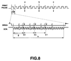
- FIG. 8 is a timing chart showing times at which address in the gamma correction memory (table) 18 is changed from one to another in one line being printed by the thermal print head.
- the thermal print head has an internal shift register.
- the thermal print head prints data for a number of dots for one line while storing the data in the internal shift register with the main and sub scanning directions being changed.
- one print pulse is for one line.
- a number g of dots in the main scanning direction for one frame can be set in dots, and the address in the gamma ( ⁇ ) data table 18 is changed per frame correspondingly to a set number of dots.
- the transfer rate of the data for the set number of dots is synchronous with a data clock DCK.
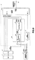
- FIG. 9 there is illustrated in the form of a block diagram the image processor in the printer in FIG. 1.
- the image processor 4 to effect the aforementioned address change in the gamma ( ⁇ ) data table 18 in the main and sub scanning directions and YMC conversion will further be described herebelow with reference to FIG. 9.
- the image processor 4 includes a YMC converter 17 to convert the R, G and B data read from the memory 8 via the memory controller 3 to Y, M and C print data, a gamma ( ⁇ ) data table 18 provided for use to effect the aforementioned gamma ( ⁇ ) correction of the Y, M and C print data from the YMC converter 17, and an address change controller 20 to supply the gamma ( ⁇ ) data table 18 with an address change signal for the address change in the main scanning direction.
- a YMC converter 17 to convert the R, G and B data read from the memory 8 via the memory controller 3 to Y, M and C print data
- a gamma ( ⁇ ) data table 18 provided for use to effect the aforementioned gamma ( ⁇ ) correction of the Y, M and C print data from the YMC converter 17, and an address change controller 20 to supply the gamma ( ⁇ ) data table 18 with an address change signal for the address change in the main scanning direction.
- the YMC converter 17 converts the R, G and B data by inverting to provide Y, M and C print data as in the following:
- the YMC converter 17 converts the R, G and B data to Y, M and C print data of 8 bits and supplies them to A0-7 of the gamma ( ⁇ ) data table 18.
- the Y, M and C data supplied to A0-7 are changed in hue using 25 gamma ( ⁇ ) data ⁇ 0 to ⁇ 24 stored in the gamma ( ⁇ ) data table 18.
- the change of the gamma ( ⁇ ) data for one line of the thermal print head, shown in FIG. 8, is effected with a change signal from the address change controller 20.
- the address change in the sub scanning direction in the gamma ( ⁇ ) data table 18 is effected by the software by CPU 6 as in the above.
- the address change controller 20 includes a counter 23 which is supplied at a CLK terminal thereof with a data clock DCK sent via the memory controller 3 and counts dots in the main scanning direction, and an address controller 25 to generate main scanning-directional address change signals of 3 bits (OUT0, OUT1 and OUT2) for example based on a count COUNT VALUE from the counter 23 and a control signal CPU CONTROL from the CPU 6 to control the main scanning-directional address in the gamma ( ⁇ ) data table 18.
- FIG. 10 is a block diagram of the address controller 25 in the image processor 4 in FIG. 9.
- the address controller 25 includes a register 26 which there is stored a number of dots counted in the main scanning direction for one frame, which will be the control signal CPU CONTROL from CPU 6, a comparator 27 to make comparison between the number of dots (reference value) supplied from the register 26 and a count from the counter 23 to determine whether they are same as each other, and a 3-bit counter 28 to count up when supplied with a one-shot pulse produced by the comparison 27 when the count is equal to the reference value.
- a register 26 which there is stored a number of dots counted in the main scanning direction for one frame, which will be the control signal CPU CONTROL from CPU 6, a comparator 27 to make comparison between the number of dots (reference value) supplied from the register 26 and a count from the counter 23 to determine whether they are same as each other, and a 3-bit counter 28 to count up when supplied with a one-shot pulse produced by the comparison 27 when the count is equal to the
- the 3-bit main scanning-directional address change signals OUT0, OUT1 and OUT2 are necessary for a maximum of 8 divisions in the direction of one line.
- 2-bit main scanning-directional address change signals are required.
- 4-bits main scanning-directional address change signals are required for a maximum of 16 divisions. That is, the main scanning-directional address change signals are required for a number of bits for a number of frames.
- the comparator 27 When the reference value set in the register 26 is equals to a count of dots in the main scanning direction, counted by the counter 23, the comparator 27 will produce a one-shot pulse and supply it to the 3-bit counter 28. It is possible to change the address of gamma ( ⁇ ) data for 5 frames in the main scanning direction using the 3 bits from the 3-bit counter 28. The one-shot pulse from the comparator 27 is fed back to the counter 23 to reset the count in the counter 23 so that one frame can be set in dots, after completion of counting for one frame.
- the image processor 4 generates image data for 25 frames changed in hue, and supplies the data to the printing block 5 which will print the image of 25 frames as shown in FIG. 5 on a printing medium by the thermal print head.
- the image frames in the print 15 are made to correspond to the asterisks (*) on the monitor screen 10 as shown in FIG. 6.
- the asterisk (*) on the monitor screen 10 is set in a position corresponding to a desired image by operating the cursor key on the keyboard of the printer, and the desired image is registered in the printer by operating the set key (EXEC) key or the like.
- the image 11 shown in FIG. 4A is adjusted in color in the image processor 4 based on a selected gamma ( ⁇ ) data and printed out.
- the color adjustment can be done at the printer shown in FIG. 1.
- the gamma ( ⁇ ) data may newly be acquired by calculation and stored at updated addresses in the gamma ( ⁇ ) data table 18.
- the user can adjust the colors without knowing about the color matching.
- the ordinary user is experienced in the subtractive mixture of colors.
- the user cannot adjust the color of an image in colors obtained by the additive mixture, displayed on the monitor of a video player for example if he has no knowledge of the complementary relation between the colors.
- the image displayed on the monitor is different in basic color appearance characteristic from the printed image, it is difficult to accurately correlate color variations in the image displayed on the monitor with those in the printed image.
- the user can judge the color matching based on a final print (the user wants to have eventually), so he can adjust the colors without the aforementioned knowledge of the complementary relation between colors.
- the color matching can be done with reduced costs and time.
- the "adjust and print" has to be repeated for the above reasons until a desired ideal hue is attained.
- printing material and time are wasted. According to the present invention, however, the printing material and time can be saved considerably.
- a variation from one printing medium to another can be absorbed.
- the variation from one ink ribbon to another can be absorbed by adjusting the color by the color adjusting method according to the present invention.
- the present invention can provide a printer and color adjusting method in which the color adjustment can be done in short time and with low cost. That is, the consumption of the printing paper can be reduced during the color adjustment. The color adjustment can be done in a reduced time. The user can easily effect the color adjustment even with no knowledge of the colors. No extra memory is required for distribution of images at addresses in the memory and no hardware and firmware are required for support such an extra memory.
Landscapes
- Engineering & Computer Science (AREA)
- Multimedia (AREA)
- Signal Processing (AREA)
- Facsimile Image Signal Circuits (AREA)
- Color Image Communication Systems (AREA)
- Color, Gradation (AREA)
- Color Television Systems (AREA)
- Fax Reproducing Arrangements (AREA)
Abstract
Description
Claims (17)
- A printer to print a video signal using printing media including a printing ink ribbon and paper, the printer comprising:an image processing means (4) for storing a plurality of data different from each other in a value on which the color appearance characteristic of the printing media depends and converting, using the plurality of data, an image composed of R, G and B video signals based on the video signal to a Y, M and C complementary-color image consisting of a desired number of columns; andmeans (5) for printing an output from the image processing means (4) using the printing media..
- The printer as set forth in claim 1, wherein the image processing means (4) has a memory means (18) in which there is stored the plurality of data different from each other in gamma value upon which the color appearance characteristic of the printing medium depends.
- The printer as set forth in claim 2, wherein the image processing means (4) calculates the plurality of data difference in gamma value from each other with reference to a reference image and changes the addresses of the data in the memory means.
- The printer as set forth in claim 1, wherein the image processing means has a complementary color converter (17) in which the R, G and B images are converted to Y, M and C images being in the complementary relation with the R, G and B images and further to Y, M and C complementary-color images for the desired number of columns.
- The printer as set forth in claim 4, wherein the conversion to the Y, M and C complementary-color images for the desired number of frames is effected by an image dividing means which divides the Y, M and C complementary-color images by the hardware in a main scanning direction and by the software in a sub scanning direction to generate Y, M and C images for the desired number of columns.
- The printer as set forth in claim 1, wherein the image processing means has a memory means (18) in which there is stored the plurality of data different from each other in a gamma value upon which the color appearance characteristic of the printing medium depends, and a complementary color converter (17) in which the R, G and B images are converted to Y, M and C images being in the complementary relation with the R, G and B images and further to Y, M and C complementary-color images for the desired number of columns using the plurality of data.
- The printer as set forth in claim 6, wherein the conversion to the Y, M and C complementary-color images for the desired number of frames is effected by an image dividing means which divides the Y, M and C complementary-color images by the hardware in a main scanning direction and by the software in a sub scanning direction to generate Y, M and C images for the desired number of columns.
- The printer as set forth in claim 1, wherein the printing medium includes a sublimation ink ribbon and printing paper.
- A color adjusting method for use in a printer to print a video signal using printing media including a printing ink ribbon and paper, the method comprising steps of:storing (8) a plurality of data different from each other in a value on which the color appearance characteristic of the printing media depends and converting(4), using the video signal, an image composed of R, G and B video signals based on the video signal to a complementary-color image consisting of a desired number of columns;printing(5) an output from the image processing step using the printing media;selecting a desired one of the plurality of images printed on the printing paper at the printing step; andadjusting the colors according to the desired image selected at the selecting step.
- The method as set forth in claim 9, wherein at the image processing step(4), the plurality of data different from each other in gamma value upon which the color appearance characteristic of the printing medium depends is stored.
- The method as set forth in claim 10, wherein at the image processing step(4), the plurality of data difference in gamma value from each other is calculated with reference to a reference image and rewritten for storage.
- The method as set forth in claim 9, wherein at the image processing step(4), the R, G and B images are converted (17) to Y, M and C images being in the complementary relation with the R, G and B images and further to Y, M and C complementary-color images for the desired number of columns.
- The method as set forth in claim 12, wherein the conversion to the Y, M and C complementary-color images for the desired number of columns is effected by dividing the Y, M and C complementary-color images by the hardware in a main scanning direction and by the software in a sub scanning direction to generate Y, M and C images for the desired number of columns.
- The method as set forth in claim 9, wherein the plurality of data different from each other in gamma value upon which the color appearance characteristic of the printing medium depends, is stored, the R, G and B images are converted to Y, M and C images being in the complementary relation with the R, G and B images and further to Y, M and C complementary-color images for the desired number of frames using the plurality of data.
- The method as set forth in claim 14, wherein the conversion to the Y, M and C complementary-color images for the desired number of frames is effected by dividing the Y, M and C complementary-color images by the hardware in a main scanning direction and by the software in a sub scanning direction to generate Y, M and C images for the desired number of columns.
- The method as set forth in claim 9, wherein the printing medium includes a sublimation ink ribbon and printing paper.
- The method as set forth in claim 9, wherein at the selecting step, the desired image is selected by prompting the user to select corresponding positions on a monitor screen to the plurality of images printed on the printing paper.
Applications Claiming Priority (2)
| Application Number | Priority Date | Filing Date | Title |
|---|---|---|---|
| JP11203724A JP2001036759A (en) | 1999-07-16 | 1999-07-16 | Printing apparatus and color adjustment method |
| JP20372499 | 1999-07-16 |
Publications (2)
| Publication Number | Publication Date |
|---|---|
| EP1069760A2 true EP1069760A2 (en) | 2001-01-17 |
| EP1069760A3 EP1069760A3 (en) | 2002-06-05 |
Family
ID=16478811
Family Applications (1)
| Application Number | Title | Priority Date | Filing Date |
|---|---|---|---|
| EP00115305A Ceased EP1069760A3 (en) | 1999-07-16 | 2000-07-14 | Printing apparatus and color adjusting method |
Country Status (3)
| Country | Link |
|---|---|
| US (1) | US6786659B1 (en) |
| EP (1) | EP1069760A3 (en) |
| JP (1) | JP2001036759A (en) |
Cited By (1)
| Publication number | Priority date | Publication date | Assignee | Title |
|---|---|---|---|---|
| CN103795993A (en) * | 2014-03-07 | 2014-05-14 | 青岛威力电子科技有限公司 | Image signal processing device of image display apparatus |
Families Citing this family (4)
| Publication number | Priority date | Publication date | Assignee | Title |
|---|---|---|---|---|
| US20090244553A1 (en) * | 2008-03-25 | 2009-10-01 | Kabushiki Kaisha Toshiba | Image processing system and image processing method |
| US8755085B2 (en) * | 2011-04-05 | 2014-06-17 | Kabushiki Kaisha Toshiba | Image forming apparatus for forming color image having tint easy to see for user |
| US9007799B2 (en) * | 2012-04-25 | 2015-04-14 | Intel Corporation | Low power content addressable memory system |
| AU2021434503A1 (en) * | 2021-03-18 | 2023-09-28 | Lexmark International, Inc. | Methods and systems for selectively preventing operation of a component |
Family Cites Families (9)
| Publication number | Priority date | Publication date | Assignee | Title |
|---|---|---|---|---|
| JP2688055B2 (en) * | 1987-11-11 | 1997-12-08 | 株式会社リコー | Image forming device |
| JPH01255542A (en) * | 1988-04-05 | 1989-10-12 | Canon Inc | Forming device for color picture image |
| US4958221A (en) * | 1988-11-08 | 1990-09-18 | Minolta Camera Kabushiki Kaisha | Digital color copying machine comprising a test mode for making a color adjustment |
| JPH04137974A (en) * | 1990-09-28 | 1992-05-12 | Sharp Corp | Video printer |
| US5504821A (en) * | 1993-03-31 | 1996-04-02 | Matsushita Electric Industrial Co., Ltd. | Color converting apparatus for performing a three-dimensional color conversion of a colored picture in a color space with a small capacity of memory |
| JPH07312691A (en) * | 1994-05-18 | 1995-11-28 | Konica Corp | Image forming device |
| US5902053A (en) * | 1995-10-11 | 1999-05-11 | Sony Corporation | Video printer having thermal head |
| US5995714A (en) * | 1996-02-16 | 1999-11-30 | Eastman Kodak Company | Method for printer calibration |
| JPH09252413A (en) * | 1996-03-18 | 1997-09-22 | Canon Inc | Image processing apparatus and method and image processing system |
-
1999
- 1999-07-16 JP JP11203724A patent/JP2001036759A/en active Pending
-
2000
- 2000-07-14 EP EP00115305A patent/EP1069760A3/en not_active Ceased
- 2000-07-15 US US09/616,331 patent/US6786659B1/en not_active Expired - Fee Related
Cited By (1)
| Publication number | Priority date | Publication date | Assignee | Title |
|---|---|---|---|---|
| CN103795993A (en) * | 2014-03-07 | 2014-05-14 | 青岛威力电子科技有限公司 | Image signal processing device of image display apparatus |
Also Published As
| Publication number | Publication date |
|---|---|
| JP2001036759A (en) | 2001-02-09 |
| US6786659B1 (en) | 2004-09-07 |
| EP1069760A3 (en) | 2002-06-05 |
Similar Documents
| Publication | Publication Date | Title |
|---|---|---|
| US8023164B2 (en) | Color adjustment apparatus, display apparatus, printing apparatus, image processing apparatus, color adjustment method, graphical user interface displaying method and program | |
| US5717839A (en) | Image processor and printer having correction table data for an external source transferred to the printer | |
| US20020005855A1 (en) | Method of and apparatus for carrying out gray conversion on color image | |
| EP0720352B1 (en) | Selective colour correction apparatus | |
| JPH0371717B2 (en) | ||
| JP2001016539A5 (en) | Image input apparatus and control method thereof, information processing apparatus and method thereof, and printing system | |
| US20090207455A1 (en) | Image processing according to image output mode | |
| JPH0444461B2 (en) | ||
| EP1447972A2 (en) | Calibrating a digital printer using a cost function | |
| JP2000066860A (en) | Printer device | |
| US6786659B1 (en) | Printing apparatus and color adjusting method | |
| EP1538825A2 (en) | Color reduction processing apparatus, printer control device, color reduction method, and printer control method | |
| US20070291287A1 (en) | Customer-based visual printer color-to-monitor color matching | |
| JPH07177367A (en) | Color image recording device | |
| JPS58220566A (en) | Operating device for color correction | |
| JP2002199236A (en) | Image processor and image processing method | |
| EP0452928A2 (en) | Multi-gradation image recording apparatus | |
| EP1398162B1 (en) | Calibration of a multilevel inkjet process | |
| US5451985A (en) | Area gradation control device and method for a thermal printer | |
| JP3994280B2 (en) | Red-eye correction device, red-eye correction method, and red-eye correction program | |
| JP2004090323A5 (en) | ||
| JP2951979B2 (en) | Color image processing equipment | |
| JP2000022954A (en) | Media density calibration method for gradation printer | |
| JP2000071578A (en) | Printer device | |
| JP4492642B2 (en) | Red-eye correction device, red-eye correction method, and red-eye correction program |
Legal Events
| Date | Code | Title | Description |
|---|---|---|---|
| PUAI | Public reference made under article 153(3) epc to a published international application that has entered the european phase |
Free format text: ORIGINAL CODE: 0009012 |
|
| AK | Designated contracting states |
Kind code of ref document: A2 Designated state(s): AT BE CH CY DE DK ES FI FR GB GR IE IT LI LU MC NL PT SE |
|
| AX | Request for extension of the european patent |
Free format text: AL;LT;LV;MK;RO;SI |
|
| PUAL | Search report despatched |
Free format text: ORIGINAL CODE: 0009013 |
|
| AK | Designated contracting states |
Kind code of ref document: A3 Designated state(s): AT BE CH CY DE DK ES FI FR GB GR IE IT LI LU MC NL PT SE |
|
| AX | Request for extension of the european patent |
Free format text: AL;LT;LV;MK;RO;SI |
|
| 17P | Request for examination filed |
Effective date: 20021009 |
|
| AKX | Designation fees paid |
Designated state(s): DE FR GB |
|
| 17Q | First examination report despatched |
Effective date: 20060420 |
|
| STAA | Information on the status of an ep patent application or granted ep patent |
Free format text: STATUS: THE APPLICATION HAS BEEN REFUSED |
|
| 18R | Application refused |
Effective date: 20090523 |