EP1069753A2 - Communication terminal - Google Patents
Communication terminal Download PDFInfo
- Publication number
- EP1069753A2 EP1069753A2 EP00115229A EP00115229A EP1069753A2 EP 1069753 A2 EP1069753 A2 EP 1069753A2 EP 00115229 A EP00115229 A EP 00115229A EP 00115229 A EP00115229 A EP 00115229A EP 1069753 A2 EP1069753 A2 EP 1069753A2
- Authority
- EP
- European Patent Office
- Prior art keywords
- incoming call
- call alert
- memory
- alert melody
- signal
- Prior art date
- Legal status (The legal status is an assumption and is not a legal conclusion. Google has not performed a legal analysis and makes no representation as to the accuracy of the status listed.)
- Withdrawn
Links
Images


Classifications
-
- H—ELECTRICITY
- H04—ELECTRIC COMMUNICATION TECHNIQUE
- H04M—TELEPHONIC COMMUNICATION
- H04M19/00—Current supply arrangements for telephone systems
- H04M19/02—Current supply arrangements for telephone systems providing ringing current or supervisory tones, e.g. dialling tone or busy tone
- H04M19/04—Current supply arrangements for telephone systems providing ringing current or supervisory tones, e.g. dialling tone or busy tone the ringing-current being generated at the substations
- H04M19/041—Encoding the ringing signal, i.e. providing distinctive or selective ringing capability
-
- H—ELECTRICITY
- H04—ELECTRIC COMMUNICATION TECHNIQUE
- H04M—TELEPHONIC COMMUNICATION
- H04M1/00—Substation equipment, e.g. for use by subscribers
- H04M1/72—Mobile telephones; Cordless telephones, i.e. devices for establishing wireless links to base stations without route selection
- H04M1/724—User interfaces specially adapted for cordless or mobile telephones
Definitions
- the present invention relates to a communication terminal such as a portable phone unit, a PHS (Personal Handy Phone System) unit, a cable phone unit, etc.
- a communication terminal such as a portable phone unit, a PHS (Personal Handy Phone System) unit, a cable phone unit, etc.
- incoming call is informed by an alert melody.
- incoming call alert melody data are stored in a memory, and the incoming call is informed by reproducing voice from the incoming call alert melody data.
- the composing function of the communication terminal is utilized.
- the communication terminal stores the melody as incoming call alert melody data in the memory.
- an incoming call alert melody is formed by switching an operation mode into a composing mode, and specifying the pitch of notes, for example, do, re, mi, etc., and the length of the notes, for example, a quarter note, an eighth note, etc. by using dial keys.
- the portable phone To reproduce melody data by using the tone generating function, the portable phone generates incoming call alert melody data by converting the melody data specified by using dial keys into a digital signal, and stores the data in the memory.
- the portable phone receives a control signal from a base station requesting to start communication, the incoming call alert melody data stored in the memory is read to announce the receipt of a call through a speaker.
- step S30 a melody is composed by using the composing function of the communication terminal.
- step S31 a memorandum is written down describing how dial keys, etc. have been operated to form an incoming call alert melody.
- step S32 the memorandum is passed to a person to whom the information representing the incoming call alert melody is to be transmitted in step S32.
- step S33 the person who receives the memorandum reads the memorandum, operates the dial keys, etc. using the composing function of the communication terminal, and forms an incoming call alert melody.
- the above mentioned conventional communication terminal can transmit the information representing the incoming call alert melody generated by a person only by transmitting a memorandum showing the input pattern. Therefore, it is very troublesome to transmit the information representing the incoming call alert melody, and it has been difficult to transmit an excellent incoming call alert melody to another person.
- An object of the present invention is to provide a communication terminal capable of easily transmitting the information representing an incoming call alert melody composed by an individual.
- the communication terminal includes communication means, a memory for storing incoming call alert melody data, and means for informing a call by an alert melody based on the incoming call alert melody data, and has the function of communicating the incoming call alert melody data with a correspondent through the communication means.
- the communication terminal can transmit the incoming call alert melody data stored in the memory to the correspondent through the communication means. Therefore, incoming call alert melody data composed by the individual can be easily transmitted.
- FIG. 1 is a block diagram of a portable phone according to an embodiment of the present invention.
- reference numeral 1 denotes a microphone for inputting voice.
- Reference numeral 2a denotes a speaker for reproducing communicated voice.
- Reference numeral 2b denotes a speaker for reproducing an incoming call alert melody.
- the speaker 2a may be omitted, with the speaker 2b used also for reproducing communicated voice.
- Reference numeral 3 denotes a PCMCODEC (Pulse Code Modulation Coder/Decoder) for converting an analog voice signal input from the microphone 1 into a digital signal, and for converting a digital signal caught by an antenna 8, then duly processed, and then fed from a memory 4 into an analog signal and then outputting the analog signal to a speaker 2.
- Reference numeral 4 denotes a memory.
- Reference numeral 5 denotes a base band engine IC (Integrated Circuit) for processing data stored in the memory 4 such that the data conform to the data format used by the modulation system used in a portable phone such as a PDC (Personal Digital Cellular) system, a CDMA (Code Division Multiple Access) system, a W-CDMA (Wideband Code Division Multiple Access) system, a GSM (Global System for Mobile Communication) system, etc.
- the IC 5 also retrieves a voice signal from the data in the data format of the modulation system used, and writes the signal to the memory 4.
- the base band engine IC 5 can also be referred to as a protocol IC.
- Reference numeral 6 denotes a modulation/demodulation circuit for digitally modulating a signal processed by the base band engine IC 5 to generate an intermediate frequency signal, and, reversely, for digitally demodulating an input intermediate frequency signal.
- Reference numeral 7 denotes a high-frequency circuit for converting an intermediate frequency signal into a high-frequency signal which can be transmitted over the air, and converting a received high-frequency signal into an intermediate frequency signal.
- the high-frequency circuit 7 includes a mixer for converting a frequency.
- Reference numeral 8 denotes an antenna for establishing radio-communication using a high-frequency signal.
- Reference numeral 9 denotes a CPU (Central Processing Unit) for controlling the entire system of the portable phone.
- Reference numeral 11 denotes an LCD (Liquid Crystal Display) for displaying various information, and is driven by an LCD driver 10 which receives a signal from the CPU 9.
- Reference numeral 13 represents dial keys, consisting of numeric buttons “0” through “9,” and buttons “*” and “#.” A button pressed among the dial keys 13 is detected by a key driver 12, and an output of the driver is transmitted to the CPU 9.
- Reference numeral 14 denotes an incoming call alert melody transmission switch for switching an operation of the portable phone into an incoming call alert melody transmission mode.
- Reference numeral 15 denotes a signal conversion circuit for converting key input information into a digital signal.
- the microphone 1 converts voice into an analog signal.
- the analog signal is converted by the PCMCODEC 3 into a digital signal, and stored in the memory 4.
- the digital signal stored in the memory 4 is processed by the base band engine IC 5 such that it conforms to the data format used by the communication system used in the portable phone.
- the digital signal processed by the base band engine IC 5 into the data format is digitally modulated by the modulation/demodulation circuit 6 to be converted into an intermediate frequency signal.
- the intermediate frequency signal is converted by the high-frequency circuit 7 into a high frequency signal, and is transmitted over the air through the antenna 8.
- a high-frequency signal received by the antenna 8 is converted by the high-frequency circuit 7 into an intermediate frequency signal, and demodulated by the modulation/demodulation circuit 6.
- the base band engine IC 5 extracts voice data, and stores It in the memory 4.
- the control signal contained in a received signal is fed from the base band engine IC 5 to the CPU 9.
- a voice signal stored in the memory 4 is converted by the PCMCODEC 3 into an analog signal, and is reproduced by the speaker 2a.
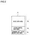
- FIG. 2 shows a memory map of the memory 4.
- reference numeral 4a denotes an area for storing voice data, and occupies a greater part of the memory 4.
- Reference numeral 4b denotes a system control data area for storing the volume level of the speaker 2, the display color of the LCD 11 such as red, green, and the like, the initial values of such settings, the telephone number of the phone unit itself, and the like.
- Reference numeral 4c denotes an incoming call alert melody data area for storing the information representing an incoming call alert melody.
- the operation of the portable phone can be switched into a composing mode by sequentially pressing the buttons of the dial keys 13 in a predetermined order. Since a pitch or a length of a note is assigned to every button of the dial keys 13 in the composing mode, an incoming call alert melody is composed by pressing a button according to a melody.
- the CPU 9 converts the key input information into a digital signal using the signal conversion circuit 15 for converting the key input information into a digital signal in accordance with the generated melody, and stores the digital signal in the incoming call alert melody data area 4c of the memory 4.
- the signal conversion circuit 15 is a circuit such as a truth table that assigns different key numbers to different digital signals one to one.
- the CPU 9 can perform a similar process using software.
- FIG. 3 shows a protocol used in communicating the incoming call alert melody signal stored in the incoming call alert melody data area 4c with a correspondent.
- step S1 one of a transmitter and a receiver calls the other, and the transmitter is connected to the receiver, thereby entering a communicating state.
- step S2 the transmitter and the receiver both press the incoming call alert melody transmission switch 14, and enter the incoming call alert melody transmission mode.
- the CPU 9 awaits input of a transmission instruction or a reception instruction based on a push tone while remaining in the communication state with the correspondent.
- the "#" button 13a indicating transmission is pushed.
- the CPU 9 for which the button 13a has been pushed awaits a reception start pattern which is a pattern tone announcing the start of reception from the receiver.
- Any communication control pattern such as the above mentioned reception start pattern is communicated as voice in the incoming call alert melody transmission mode.
- the base band engine IC 5 of the transmitter writes the voice data of the reception start pattern to the memory 4.
- the CPU 9 determines whether or not the received voice data is the reception start pattern by comparing the reception start pattern with a pattern having been stored in the memory 4 by the signal conversion circuit 15.
- the signal conversion circuit 15 converts signals generated by operation of the keys 13 into tones and stores them in the memory 4.
- the "*" button 13b indicating reception is pushed.
- the CPU 9 for which the button 13b has been pushed transmits a reception start pattern to the transmitter in step S3.
- the CPU 9 automatically issues an instruction and transmits a transmission start pattern in step S4.
- the CPU 9 of the receiver determines whether or not the transmission start pattern has been received from the transmitter in the method similar to the above mentioned method.
- the CPU 9 compares the voice data stored in and received from the memory 4 with the transmission start pattern stored in the memory 4. If they match each other, it is determined that the transmission start pattern has been received. Other control patterns are determined similarly.
- the receiver When the receiver receives the transmission start pattern, it transmits a transmission OK data to the transmitter in step S5, and awaits incoming call alert melody data.
- a transmission start pattern, and a transmission OK data the tone of their respective pattern may be transmitted either once or a plurality of times. It is preferable that these control patterns be such as are not included in voice data so that a control pattern cannot be confused with voice data.
- the transmitter When the transmitter receives a transmission OK data, it transmits a data transmission pattern in step S6, transmits the information about an incoming call alert melody with a CRC (Cyclic Redundancy Check) code for error detection in step S7, and finally transmits a data transmission end pattern in step S8.
- CRC Cyclic Redundancy Check
- a data transmission pattern refers to, for example, a tone of which the voice data retrieved by the base band engine IC 5 have “1"s in continuous 100 bits, and then a "0" in the 101st bit.
- the receiver When the receiver is receiving the "1"s of a data transmission pattern, it does not write data to the incoming call alert melody data area 4c, and starts writing data after receiving the "0" to the incoming call alert melody data area 4c. Thus, the receiver checks the timing of writing data to the incoming call alert melody data area 4c according to the data transmission pattern.
- a data transmission end pattern can also be a tone having "1"s in continuous 100 bits.
- the transmitter uses the base band engine IC 5 to process incoming call alert melody data stored in the incoming call alert melody data area 4c, uses the modulation/demodulation circuit 6 to modulate the data, and uses the high-frequency circuit 7 to convert the data into a high-frequency signal, thereby transmitting the data over the air.
- the receiver uses the high-frequency circuit 7 to convert a received signal into an intermediate frequency signal, uses the modulation/demodulation circuit 6 to demodulate the signal, and uses the base band engine IC 5 to retrieve voice data, thereby successfully writing the incoming call alert melody data to the incoming call alert melody data area 4c.
- the portable phone can establish communication of incoming call alert melody data in substantially the same procedure as the procedure for the voice communication. Accordingly, the contents of the data stored in the incoming call alert melody data area 4c of the receiver are the same as the contents of the incoming call alert melody data stored in the incoming call alert melody data area 4c of the transmitter.
- the receiver checks whether or not there is a data error in the information about received incoming call alert melody using a CRC code. If there are no errors, then the reception end pattern is transmitted in step S9 after the data transmission end pattern is received, the incoming call alert melody transmission mode is terminated, and control is returned to the normal communication state. When the transmitter receives a reception end pattern, the incoming call alert melody transmission mode is terminated, and control is returned to the normal communication mode.
- the receiver transmits a re-transmission request pattern instead of the reception end pattern in step S9 after the data transmission end pattern is received, and maintains the incoming call alert melody transmission mode.
- the transmitter transmits a transmission start pattern after returning control to step S4, and re-transmits the incoming call alert melody data.
- a portable phone receives a control signal which requests communication from a base station when it is not in the communication state, then the CPU 9 is notified that the control signal is received from the base band engine IC 5. Therefore, the CPU 9 instructs to transmit the incoming call alert melody data stored in the incoming call alert melody data area 4c of the memory 4 to the PCMCODEC 3 through the base band engine IC 5.
- the incoming call alert melody data is converted into an analog signal by the PCMCODEC 3, and reproduced by the speaker 2. Thus, the melody announces the reception of a call.
- the CPU 9 instructs to notify the base station that the control signal has been received, communication is established by some control signals communicated between the portable phone and the base station, and voice data is transmitted from the base station to the portable phone.
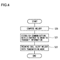
- the user when a user tries to transmit incoming call alert melody data using the portable phone according to the present embodiment, the user composes an incoming call alert melody using the composing function in step S20 as shown in FIG. 4. Then, in step S21, the user enters the communication state with a correspondent to whom information is to be transmitted. In step S22, the user presses the incoming call alert melody transmission switch 14 to enter the incoming call alert melody transmission mode, thereby transmitting the information about the incoming call alert melody to the correspondent. As a result, the information about an incoming call alert melody can be easily transmitted.
- a specific button such as the button "1" among the dial keys 13 can be pressed for several seconds in the communication state to make the CPU 9 switch the operation into the incoming call alert melody transmission mode on a software basis.
- the incoming call alert melody data can be easily transmitted.
- the operation of the portable phone can be switched into the incoming call alert melody transmission mode by pressing the buttons in the order of "1,” "2,” “3,” “4,” “5,” “6,” “7,” “8,” “9,” and "#.”
- a melody can be composed using a personal computer.
- the personal computer is connected to a telephone cable through a modem, and the personal computer functions as a transmitter while a portable phone functions as a receiver, thereby successfully transmitting incoming call alert melody data from the personal computer to the portable phone.
- the protocol shown in FIG. 3 can be designed not to use a CRC code when the transmitter transmits incoming call alert melody data in step S7.
- the receiver cannot check whether or not there are errors in the received incoming call alert melody data, but the transmitter can return control to the normal communication state by canceling the incoming call alert melody transmission mode immediately after transmitting the data transmission end pattern in step S8, and the receiver can return control to the normal communication state by canceling the incoming call alert melody reception mode immediately after receiving the data transmission end pattern.
- communication using a CRC code added to the incoming call alert melody data as in the embodiment offers higher reliability.
- the receiver can also determine the end of the received incoming call alert melody data. Therefore, the protocol does not require a data transmission end pattern. For example, since the length of a piece of music is variable, 10 kilobits of information is transmitted from a transmitter to a receiver whenever incoming call alert melody data is transmitted even if, whereas the incoming call alert melody data area 4c has a capacity of 10 kilobits, the actual data is 6 kilobits long.
- the protocol does not require a data transmission end pattern.
- the "#" button indicates transmission while the "*” button indicates reception.
- other buttons may be used for these purposes.
- incoming call alert melody data to a correspondent through data communication, i.e. non-voice communication, such as conforming to the PIAFS (PHS Internet Access Forum Standard) that permits a PHS unit to communicate on the Internet, but it is more convenient to communicate incoming call alert melody data using the normal voice communication according to the present embodiment, and it is easier to transfer data between models having different melody-data input systems.
- data communication i.e. non-voice communication, such as conforming to the PIAFS (PHS Internet Access Forum Standard) that permits a PHS unit to communicate on the Internet, but it is more convenient to communicate incoming call alert melody data using the normal voice communication according to the present embodiment, and it is easier to transfer data between models having different melody-data input systems.
- PIAFS PHS Internet Access Forum Standard
- the present embodiment has been described above about the portable phone, it is not limited to such application; that is, it can be applied to a wireless communication terminal such as a PHS, a transceiver, etc., and a wired communication terminal such as a cable phone.
- an incoming call alert melody data composed by a user can be easily transmitted.
- incoming call alert melody data composed by another person can be stored in the communication terminal without composing an incoming call alert melody by operating a communication terminal while referring to a memo as in the conventional method. This permits easy changing of the incoming call alert melody.
Landscapes
- Engineering & Computer Science (AREA)
- Signal Processing (AREA)
- Mobile Radio Communication Systems (AREA)
- Telephone Function (AREA)
- Reverberation, Karaoke And Other Acoustics (AREA)
- Telephonic Communication Services (AREA)
- Electrophonic Musical Instruments (AREA)
Abstract
Description
Claims (10)
- A communication terminal, comprising:a memory for storing incoming call alert melody data;means for reading out the incoming call alert melody data from said memory when a call is received; andincoming call alert melody data communication means for communicating the incoming call alert melody data with a counterpart communication terminal.
- A communication terminal according to claim 1,
wherein said incoming call alert melody data communication is established in an incoming call alert melody data communication mode; andsaid incoming call alert melody data communication mode is established with a transmitter side and a receiver side in a communicating state. - A communication terminal, comprising:a composing function of composing an incoming call alert melody by operating a key provided in the communication terminal;a memory for storing information corresponding to said composed incoming call alert melody;means for reading out a melody data from said memory when a call is received;a speaker for converting said read melody data into voice; andmeans for transmitting the melody data in said memory to another communication device.
- The communication terminal according to claim 3,
wherein said incoming call alert melody data communication is established in an incoming call alert melody data communication mode; andsaid incoming call alert melody data communication mode is established with a transmitter side and a receiver side in a communicating state. - A portable phone device, comprising:a telephone circuit having a microphone, speaker means, memory, a CODEC circuit, a base band engine circuit, a modulation/demodulation circuit, a high-frequency circuit, and dial keys;a transmission function of converting a voice signal input from the microphone into a digital signal by the CODEC circuit, storing the signal in the memory, reading the signal stored in the memory, converting the signal into a predetermined data format by the base band engine circuit, modulating the signal by the modulation/demodulation circuit, and transmitting the modulated signal through the high-frequency circuit and the antenna;a reception function of demodulating by the modulation/demodulation circuit a high-frequency signal received through the antenna to extract a signal in a predetermined format, retrieving a voice signal by the base band engine circuit, storing the signal in the memory, reading the signal from the memory, converting the signal into an analog signal by the CODEC circuit, and outputting voice by the speaker means;a call notification function of reading an incoming call alert melody from the memory when a reception start control signal is received, D/A converting the melody by the CODEC circuit, and outputting voice by the speaker means; andan incoming call alert melody data transmission function of reading incoming call alert melody data from the memory, and transmitting the data through the base band engine circuit, the modulation/demodulation circuit, the high-frequency circuit, and the antenna.
- The portable phone device according to claim 5, further comprising an incoming call alert melody data reception function of reading the melody data caught by the antenna into the memory through the high-frequency circuit, the modem circuit, and the base band engine circuit.
- The portable phone device according to claim 5, further comprising a switch for setting an incoming call alert melody data communication mode.
- The portable phone device according to claim 7, wherein said incoming call alert melody data communication mode is set in a state in which a transmitter and a receiver enter a communication state.
- The portable phone device according to claim 5, wherein said speaker means is used both for voice communication and for incoming call alert melody reproduction.
- The portable phone device according to claim 5, wherein said speaker means has a first speaker for voice communication and a second speaker for incoming call alert melody reproduction.
Applications Claiming Priority (2)
| Application Number | Priority Date | Filing Date | Title |
|---|---|---|---|
| JP19997699 | 1999-07-14 | ||
| JP11199976A JP2001028617A (en) | 1999-07-14 | 1999-07-14 | Communication terminal |
Publications (2)
| Publication Number | Publication Date |
|---|---|
| EP1069753A2 true EP1069753A2 (en) | 2001-01-17 |
| EP1069753A3 EP1069753A3 (en) | 2002-05-15 |
Family
ID=16416724
Family Applications (1)
| Application Number | Title | Priority Date | Filing Date |
|---|---|---|---|
| EP00115229A Withdrawn EP1069753A3 (en) | 1999-07-14 | 2000-07-13 | Communication terminal |
Country Status (2)
| Country | Link |
|---|---|
| EP (1) | EP1069753A3 (en) |
| JP (1) | JP2001028617A (en) |
Cited By (2)
| Publication number | Priority date | Publication date | Assignee | Title |
|---|---|---|---|---|
| EP1255418A3 (en) * | 2001-03-02 | 2003-09-10 | Nokia Corporation | Method and apparatus for combining properties in mobile station |
| EP1542436A1 (en) * | 2003-12-08 | 2005-06-15 | Dialog Semiconductor GmbH | Light show ASIC |
Families Citing this family (2)
| Publication number | Priority date | Publication date | Assignee | Title |
|---|---|---|---|---|
| JP2002323897A (en) * | 2001-04-25 | 2002-11-08 | Noritz Corp | Reporting sound generator |
| JP2002346035A (en) * | 2001-05-25 | 2002-12-03 | Samii Kk | Game machine, portable information terminal and program used therefor |
Family Cites Families (7)
| Publication number | Priority date | Publication date | Assignee | Title |
|---|---|---|---|---|
| CN1192557C (en) * | 1996-12-06 | 2005-03-09 | 皇家菲利浦电子有限公司 | Telecommunication device and a method for providing ringing information |
| FI105308B (en) * | 1996-12-30 | 2000-07-14 | Nokia Mobile Phones Ltd | Programming a phone's ringtones |
| JP3602322B2 (en) * | 1997-08-25 | 2004-12-15 | 株式会社日立製作所 | Mobile phone equipment |
| JP3496481B2 (en) * | 1997-10-24 | 2004-02-09 | 株式会社デンソー | Wireless communication device |
| JPH11187084A (en) * | 1997-12-19 | 1999-07-09 | Oki Electric Ind Co Ltd | Ring back tone registering method, receiver and ring back tone registering device |
| JPH11215249A (en) * | 1998-01-29 | 1999-08-06 | Denso Corp | Telephone equipment |
| JP2000106685A (en) * | 1998-09-28 | 2000-04-11 | Ntt Mobil Communication Network Inc | Wireless terminal |
-
1999
- 1999-07-14 JP JP11199976A patent/JP2001028617A/en active Pending
-
2000
- 2000-07-13 EP EP00115229A patent/EP1069753A3/en not_active Withdrawn
Cited By (3)
| Publication number | Priority date | Publication date | Assignee | Title |
|---|---|---|---|---|
| EP1255418A3 (en) * | 2001-03-02 | 2003-09-10 | Nokia Corporation | Method and apparatus for combining properties in mobile station |
| US7835771B2 (en) | 2001-03-02 | 2010-11-16 | Nokia Corporation | Method and apparatus for combining properties in mobile station |
| EP1542436A1 (en) * | 2003-12-08 | 2005-06-15 | Dialog Semiconductor GmbH | Light show ASIC |
Also Published As
| Publication number | Publication date |
|---|---|
| JP2001028617A (en) | 2001-01-30 |
| EP1069753A3 (en) | 2002-05-15 |
Similar Documents
| Publication | Publication Date | Title |
|---|---|---|
| CA2205581C (en) | Incoming calling system | |
| JPH0685745A (en) | Dual mode wireless communication device | |
| US7123903B2 (en) | Wireless telephone and wireless telephone system | |
| US5893032A (en) | Mobile communication subscriber apparatus and method for setting a function of answering machine | |
| KR100312032B1 (en) | Character service method for cellular phone | |
| EP1069753A2 (en) | Communication terminal | |
| JP2003069700A (en) | Communication terminal | |
| JP3551455B2 (en) | Communication system, network management device, and communication terminal device | |
| JP3201245B2 (en) | Cordless phone system | |
| JP2003110678A (en) | Mobile radio terminal | |
| JPH0345072A (en) | Facsimile equipment | |
| JPH11187084A (en) | Ring back tone registering method, receiver and ring back tone registering device | |
| JPH10145510A (en) | Communication terminal equipment | |
| JPH0345070A (en) | facsimile machine | |
| KR20030071247A (en) | Transmit and Receive Method for a phone book each other the mobile phone using blue-tooth technique | |
| JP2003115920A (en) | Communication terminal | |
| JPH0619228Y2 (en) | Wireless phone | |
| JP2001044946A (en) | Communication terminal device | |
| KR100247045B1 (en) | Mobile communication terminal including speech unit and radiotransmission and reception unit | |
| KR100217225B1 (en) | Mobile terminal having function to be capable of directly connecting with pstn | |
| JPH0352441A (en) | Radio telephone system | |
| JP3377425B2 (en) | Wireless telephone | |
| KR100238523B1 (en) | How to control a fixed device using a mobile device in a cordless phone | |
| JPH10200647A (en) | Wireless telephone | |
| JPH06112891A (en) | Portable telephone set, on-vehicle radio equipment and on-vehicle portable telephone set |
Legal Events
| Date | Code | Title | Description |
|---|---|---|---|
| PUAI | Public reference made under article 153(3) epc to a published international application that has entered the european phase |
Free format text: ORIGINAL CODE: 0009012 |
|
| AK | Designated contracting states |
Kind code of ref document: A2 Designated state(s): AT BE CH CY DE DK ES FI FR GB GR IE IT LI LU MC NL PT SE |
|
| AX | Request for extension of the european patent |
Free format text: AL;LT;LV;MK;RO;SI |
|
| PUAL | Search report despatched |
Free format text: ORIGINAL CODE: 0009013 |
|
| AK | Designated contracting states |
Kind code of ref document: A3 Designated state(s): AT BE CH CY DE DK ES FI FR GB GR IE IT LI LU MC NL PT SE |
|
| AX | Request for extension of the european patent |
Free format text: AL;LT;LV;MK;RO;SI |
|
| 17P | Request for examination filed |
Effective date: 20020912 |
|
| AKX | Designation fees paid |
Designated state(s): DE FR GB |
|
| STAA | Information on the status of an ep patent application or granted ep patent |
Free format text: STATUS: THE APPLICATION HAS BEEN WITHDRAWN |
|
| 18W | Application withdrawn |
Effective date: 20070618 |