EP1069718B1 - Conversion of seamless concatenation into virtual concatenation in a synchronous digital data transmission network - Google Patents
Conversion of seamless concatenation into virtual concatenation in a synchronous digital data transmission network Download PDFInfo
- Publication number
- EP1069718B1 EP1069718B1 EP00440200A EP00440200A EP1069718B1 EP 1069718 B1 EP1069718 B1 EP 1069718B1 EP 00440200 A EP00440200 A EP 00440200A EP 00440200 A EP00440200 A EP 00440200A EP 1069718 B1 EP1069718 B1 EP 1069718B1
- Authority
- EP
- European Patent Office
- Prior art keywords
- multiplex units
- multiplex
- payload data
- units
- concatenation
- Prior art date
- Legal status (The legal status is an assumption and is not a legal conclusion. Google has not performed a legal analysis and makes no representation as to the accuracy of the status listed.)
- Expired - Lifetime
Links
- 230000001360 synchronised effect Effects 0.000 title claims abstract description 35
- 230000005540 biological transmission Effects 0.000 title claims description 30
- 238000006243 chemical reaction Methods 0.000 title claims description 13
- 230000002093 peripheral effect Effects 0.000 claims abstract description 20
- 238000000034 method Methods 0.000 claims description 12
- 230000007274 generation of a signal involved in cell-cell signaling Effects 0.000 claims 1
- 238000012546 transfer Methods 0.000 abstract description 2
- 238000004891 communication Methods 0.000 description 19
- 238000012545 processing Methods 0.000 description 15
- 239000011159 matrix material Substances 0.000 description 11
- RGNPBRKPHBKNKX-UHFFFAOYSA-N hexaflumuron Chemical compound C1=C(Cl)C(OC(F)(F)C(F)F)=C(Cl)C=C1NC(=O)NC(=O)C1=C(F)C=CC=C1F RGNPBRKPHBKNKX-UHFFFAOYSA-N 0.000 description 4
- 238000007726 management method Methods 0.000 description 4
- 230000006835 compression Effects 0.000 description 3
- 238000007906 compression Methods 0.000 description 3
- 238000010586 diagram Methods 0.000 description 3
- 230000006870 function Effects 0.000 description 3
- 230000002457 bidirectional effect Effects 0.000 description 2
- 238000001514 detection method Methods 0.000 description 2
- 230000007704 transition Effects 0.000 description 2
- 241001370750 Echinopsis oxygona Species 0.000 description 1
- 230000000712 assembly Effects 0.000 description 1
- 238000000429 assembly Methods 0.000 description 1
- 230000001419 dependent effect Effects 0.000 description 1
- 238000011156 evaluation Methods 0.000 description 1
- 239000000945 filler Substances 0.000 description 1
- 238000002372 labelling Methods 0.000 description 1
- 230000003287 optical effect Effects 0.000 description 1
- 238000012856 packing Methods 0.000 description 1
- 230000009993 protective function Effects 0.000 description 1
- 238000011144 upstream manufacturing Methods 0.000 description 1
Images

Classifications
-
- H—ELECTRICITY
- H04—ELECTRIC COMMUNICATION TECHNIQUE
- H04J—MULTIPLEX COMMUNICATION
- H04J3/00—Time-division multiplex systems
- H04J3/16—Time-division multiplex systems in which the time allocation to individual channels within a transmission cycle is variable, e.g. to accommodate varying complexity of signals, to vary number of channels transmitted
- H04J3/1605—Fixed allocated frame structures
- H04J3/1611—Synchronous digital hierarchy [SDH] or SONET
-
- H—ELECTRICITY
- H04—ELECTRIC COMMUNICATION TECHNIQUE
- H04J—MULTIPLEX COMMUNICATION
- H04J2203/00—Aspects of optical multiplex systems other than those covered by H04J14/05 and H04J14/07
- H04J2203/0001—Provisions for broadband connections in integrated services digital network using frames of the Optical Transport Network [OTN] or using synchronous transfer mode [STM], e.g. SONET, SDH
- H04J2203/0089—Multiplexing, e.g. coding, scrambling, SONET
- H04J2203/0094—Virtual Concatenation
-
- Y—GENERAL TAGGING OF NEW TECHNOLOGICAL DEVELOPMENTS; GENERAL TAGGING OF CROSS-SECTIONAL TECHNOLOGIES SPANNING OVER SEVERAL SECTIONS OF THE IPC; TECHNICAL SUBJECTS COVERED BY FORMER USPC CROSS-REFERENCE ART COLLECTIONS [XRACs] AND DIGESTS
- Y10—TECHNICAL SUBJECTS COVERED BY FORMER USPC
- Y10S—TECHNICAL SUBJECTS COVERED BY FORMER USPC CROSS-REFERENCE ART COLLECTIONS [XRACs] AND DIGESTS
- Y10S370/00—Multiplex communications
- Y10S370/901—Wide area network
- Y10S370/902—Packet switching
- Y10S370/903—Osi compliant network
- Y10S370/907—Synchronous optical network, SONET
Definitions
- the invention relates to a method for transmitting user data via a synchronous digital communication network according to the preamble of Claim 1 and a multiplexer for a synchronous digital Communication network according to the preamble of claim 5 and a Peripheral device according to the preamble of claim 6.
- a synchronous digital message transmission network such as in SDH or SONET systems
- messages to be transmitted are transmitted as a payload by multiplex units.
- multiplex units are referred to as virtual containers, in SONET as virtual tributaries .
- STM-N 1, 4, 16, 64
- the largest multiplex unit is the virtual container VC-4 with a payload capacity of 149.760 Mbit.
- the VC-4 is referred to as AU-4 ( Administrative Unit ).
- the largest multiplex unit at SONET is a VT-3 with a capacity of 48.384 Mbit, which together with a corresponding pointer is referred to as AU-3. If payload signals whose bit rate is greater than the payload of the largest multiplex unit are to be transmitted, a chain of several multiplex units is formed.
- peripheral devices e.g. for IP routers that are synchronous use digital communications network as a backbone network that is seamless Chaining is preferred because it is easier to handle from a network perspective preferred virtual linking because of the greater flexibility.
- the Conversion from seamless chaining to virtual chaining is in itself known.
- the individual multiplex units are each with one provide your own pointer.
- An identification in the head area (overhead) of the Multiplex units refer to the concatenation. For labeling currently uses bits 1 and 2 of the H4 byte, using others However, overhead bytes are also conceivable.
- the virtually chained Multiplex units can then be in separate transport modules be transported.
- an SDH multiplexer is used for the purpose of transportation an ATM data stream (Asynchronous Transfer Mode) a conversion of runs seamless chaining in virtual chaining and that in seamless Concatenation contained ATM data stream by inverse multiplexing into a number divides slower parallel data streams, which are then used as the respective payload in the individual virtually chained multiplex units can be transported.
- ATM data stream Asynchronous Transfer Mode
- peripheral devices such as e.g. IP router preferred the seamless chaining.
- IP router preferred the seamless chaining.
- the device optionally with a OC-3c / STM-1c interface or with an OC-12c / STM-4c interface can be equipped.
- Both types of interfaces use seamless Concatenation of multiplex units. Because the number of seamlessly chained Multiplex units depends on the interface type of the router regardless of the bandwidth actually used for IP payload transmit the same number of multiplex units.
- the object of the invention is a method for the transmission of user data to specify via a synchronous digital communications network, at the number of chained multiplex units to the actually required Bandwidth can be adjusted.
- Another object of the invention consists of a multiplexer for a synchronous digital Communication network and a peripheral specify that are suitable for carrying out the method according to the invention.
- a basic idea of the invention is to provide seamless peripheral equipment Generate concatenation of multiplex units, but only a part of the concatenated multiplex units to use for payload and the rest leave blank or fill up with a fill pattern.
- Another The basic idea of the invention is that the multiplexer on Transition to a synchronous digital communications network Performs the seamless chaining to virtual chaining and omits those multiplex units that are not included in the conversion Payload are filled. Thus an adjustment of the number of chained Multiplex units to the bandwidth actually required at the Conversion from seamless chaining to virtual chaining performed.
- the transmission can also be bidirectional.
- FIG. 1 shows how one from a first peripheral device 10 Payload over a synchronous digital communications network SDH too is transmitted to a second peripheral device 16.
- the peripheral devices are IP router and the payload consists of data packets that follow the Internet protocol are structured.
- the first IP router 10 is a synchronous Message signal 11 generated. It is a frame-structured multiplex signal of the type STM-4.
- the STM-4 frame consists of four byte-by-nested transport modules of type STM-1. Each of the four STM-1 frames contains a multiplex unit VC-4.
- IP router 10, 16 are part of a data network and use the synchronous digital SDH communication network as a backbone network.
- the synchronous message signal 11 arrives from the first IP router 10 a multiplexer 12 of the synchronous digital communications network SDH.
- each of the four multiplex units has its own Provide pointer and there is a marking in the head area (overhead) of the multiplex units inserted, which indicates the chaining.
- the four Virtually chained multiplex units VC-4 can now be used independently of each other in separate smaller or common larger ones Transport modules are transmitted through the SDH communications network. in the Embodiment is indicated that each of the four virtually chained Multiplex units is transmitted over its own path 13a-d.
- the virtual chaining is called VC-4-4v.
- the virtual concatenated multiplex units are now replaced by the SDH data transmission network for data sink, a second multiplexer 14 transferred. This converts the virtual chain back into a seamless one Chaining and transmits the four seamlessly linked multiplex units in a message signal 15 structured into STM-4 frames to the second IP router 16.
- the multiplexers can be so-called add / drop multiplexers or are terminal multiplexers, the individual or all paths terminate that in the received frame structured multiplex signals are included.
- the IP router 10 only packs three of the four concatenated multiplex units VC-4-4c.
- the fourth multiplex unit remains empty.
- the message signal 11 that the IP router 10 sends to the multiplexer 12 transmits, but still has the same structure, namely an STM-4 frame with four seamlessly linked multiplex units VC-4-4c.
- Multiplexer 12 will seamlessly chain into virtual chaining converted.
- the fourth is not packed with data packets Multiplex unit omitted. This creates a virtual chain three multiplex units VC-4-3v, which via paths 13a-c to the second Multiplexer 14 is transmitted. There the virtual chaining becomes closed again converted into a seamless chain and with an empty multiplex unit added to VC-4-4c transmitted to the second IP router 16.
- the IP router Because the STM-4 frame consists of four STM-1 frames nested in bytes , it is extremely easy for the IP router to free a multiplex unit leave: He simply inserts a filler byte (e.g. hex00) after three bytes.
- the Multiplexer needed to convert seamless chaining of four Multiplex units in a virtual chain of three multiplex units Information which and which of the four multiplex units should be omitted.
- the IP router provides the information. This can either be via a dedicated control channel in the head area of the Multiplex units or transport modules or via a higher-level Network management system. Another option is that in the multiplexer automatically e.g.
- the automatic detection can Monitor the payload in the multiplexer, or else in that unused multiplex units from the IP router in the header be marked.
- IP packets are in HDLC frames framed. Bytes between the HDLC frames are fill patterns.
- the invention is not restricted to a chaining of virtual containers from Type VC-4.
- VC-12 containers with a Payload of 2 Mbit can be used.
- the conversion to a small number of virtually chained Multiplex units can also be predefined so that e.g. To determine Times the full bandwidth of all multiplex units is available, too other times only a reduced capacity. For example, from 8:00 to 10:00 and from 16:00 to 18:00 a chain of three VC-4 be selected, a virtual one at peak times from 10 a.m. to 4 p.m. Chaining of all four VC-4 and in non-productive times from 6:00 p.m. to 8:00 a.m. from just one or two VC-4. So the actually transmitted payload can the statistical utilization of the data network can be adjusted. Alternatively, you can also a dynamic adjustment after a determined Traffic around every 10 minutes. respectively. Will be a preset used, the transmission of the information is omitted Multiplex units currently used for data packets are used by the IP router the multiplexer.
- Another preferred use of the method according to the invention is for Transmission of data packets according to the protocol for asynchronous Transport mode (ATM) are structured.
- ATM asynchronous Transport mode
- Ethernet frames are framed in HDLC frames and are transported transparently in linked SDH containers. Between A fill pattern can be inserted in HDLC frames Compression according to the invention is removed, so the number of to reduce linked containers.
- the IP router 40 of the exemplary embodiment is in one in FIG Block diagram shown schematically. It has several LAN interfaces 45 (LAN: local area network), which corresponds to the standard for Ethernet IEEE 802.3 using an asynchronous transmission method Collision detection work. There is a local one on each of the LAN interfaces Data network connected and the IP router 40 receives data packets IP structured according to the internet protocol. The data packets are from the LAN interfaces to an IP matrix 41. This decides based on the destination address of each data packet, where it should be sent. Data packets for another data network connected to the IP router are sent to the corresponding LAN interface. The other data packets, i.e.
- the data packets that are not for one of the to the LAN interfaces connected local data networks are determined, are switched from the IP matrix 41 to a processing unit 42.
- There four multiplex units of the type VC-4 are formed and with the Packed data packets.
- the packed multiplex units are sent to one Processing unit 43 for transport modules of type STM-4 forwarded, where by seamless chaining and byte-by-byte nesting of the four A frame-structured multiplex signal of the type STM-4, VC-4-4c is formed, which is then on the interface I / O 44 as synchronous Message signal is sent.
- a pointer determines and in the head area of the transport modules written, which points to the beginning of the first multiplex unit.
- the Interface I / O 44 is an optical interface.
- the IP router 40 also has a control device 46, which is connected to the IP matrix 41 and the processing unit 42 for multiplex units VC-4 connected is.
- a current traffic volume is recorded in the IP matrix 41 determined and passed to the control device 46. This decides then at regular intervals in accordance with the Traffic volume or alternatively according to a given Schedule how many of the four multiplex units are packed with data packets and communicates this to the VC-4 processor 42. Accordingly, only the selected multiplex units are packed, the rest are packed with a Fill pattern filled. They are not in the processing unit 42 packed multiplex units marked in the header. For this one of the reserved overhead bytes used for proprietary purposes.
- the IP router can also be configured so that only two or three of the four seamlessly linked multiplex units can be filled with user data. In this case, a control device 46 is not necessary.
- the Processing unit 42 is then set so that only the predetermined ones Multiplex units are packed with IP packets and the rest are always free stay.
- the IP matrix 41 has a filter function executes since only such IP packets from the matrix to the VC-4 processing unit be routed through the synchronous digital Message transmission network transported to other local data networks should not be directly on a LAN interface of the IP router are connected.
- the IP matrix 41 can also have a further filter function execute by sending data packets whose delivery via the synchronous digital communication network is not possible, discards or with a sends the corresponding error message back to the sender.
- Such Filter function can be done by making appropriate entries in the routing table IP matrix can be executed. So nonexistent or due incorrect IP addresses are filtered out due to a configuration error.
- a protective function in the manner of a firewall can be achieved in this way will be realized.
- the multiplexer 50 which receives the synchronous message signal, the converts seamless chaining into virtual chaining and that Multiplex units via the synchronous message transmission system is shown schematically in Figure 5. He receives on a first Interface I / O 51 the synchronous message signal from the Peripheral. In a first processing unit 52 for transport modules of type STM-4 the byte-by-byte interleaving is resolved and the pointer evaluated on the first multiplex unit. According to the pointer value the four linked multiplex units are read out and sent to a first one Processing unit 53 for multiplex units of the type VC-4 directed. There the head area of the individual multiplex units is evaluated. A Mark indicating that the corresponding multiplex unit is not is filled with user data, is recognized and the corresponding multiplex unit then discarded.
- the information about this is also sent to a Control device 55 forwarded.
- the remaining multiplex units are buffered in a buffer memory 54.
- the second VC-4 processing unit receives from the control unit 56 the information, which and how many Multiplex units can be combined into a virtual chain should.
- the virtual chaining is done by a corresponding one Identification in the head area of the multiplex units. This is currently the H4 byte used.
- the concatenated multiplex units then become a second one Processing unit 57 for transport modules of type STM-4 fed where they are each packed in their own STM-1 frame.
- the STM-1 frame are interleaved byte by byte to create a transport module from Type STM-4 to form an existing synchronous message signal, which then at a second interface I / O 58 in dos synchronous digital Message transmission network is sent.
- the second STM-4 processing unit 56 also determines a pointer for each of the Multiplex units, which points to the beginning of the respective multiplex unit and written in the header of the respective STM-1 transport modules becomes.
- the input signal of the multiplexer contains one Seamless interlinking VC-4-4c from four multiplex units of the type VC-4.
- the four multiplex units are not for transport, for example used by user data and identified as such in the header area.
- So an output signal is formed that a virtual chain VC-4-3v contains three multiplex units VC-4.
- the rest Transmission capacity can be used for additional traffic, for example for a Bundle of telephone connections can be used.
- the Multiplexer the network management system with how many multiplex units the virtual chain includes, therefore, via the network management system the free transmission capacity can be allocated for other purposes.
- the header area can indicate which of the chained Multiplex units are used for the transport of user data, too via the network management system from the peripheral device to the Multiplexers are forwarded.
- the multiplexer Evaluation of the payload contained in each multiplex unit takes place in order to determine which of the multiplex units are packed with user data and which are unused.
- the multiplexer can be a terminal multiplexer, a Add / drop multiplexer or a digital cross-connect. He can also further assemblies such as a time and space switching matrix for Multiplex units and other interfaces to the Have communication network.
- Type VC-4 multiplex units can also do other, smaller ones Sub-units from the multiplex hierarchy of the transmission system are used, such as VC-12 or VC-3.
- An alternative embodiment of the peripheral device is an ATM switch. This is constructed similarly to the IP router in Figure 4, but has corresponding ATM interfaces instead of the LAN interfaces and instead the IP matrix is a switching matrix for ATM cells.
Landscapes
- Engineering & Computer Science (AREA)
- Computer Networks & Wireless Communication (AREA)
- Signal Processing (AREA)
- Data Exchanges In Wide-Area Networks (AREA)
- Time-Division Multiplex Systems (AREA)
- Mobile Radio Communication Systems (AREA)
- Communication Control (AREA)
Abstract
Description
Die Erfindung betrifft ein Verfahren zum Übertragen von Nutzdaten über ein synchrones digitales Nachrichtenübertragungsnetz nach dem Oberbegriff des Anspruchs 1 sowie einen Multiplexer für ein synchrones digitales Nachrichtenübertragungsnetz nach dem Oberbegriff des Anspruchs 5 und ein Peripheriegerät nach dem Oberbegriff des Anspruchs 6.The invention relates to a method for transmitting user data via a synchronous digital communication network according to the preamble of Claim 1 and a multiplexer for a synchronous digital Communication network according to the preamble of claim 5 and a Peripheral device according to the preamble of claim 6.
In einem synchronen digitalen Nachrichtenübertragungsnetz wie beispielsweise in SDH- oder SONET-Systemen werden zu übertragende Nachrichten als Nutzlast von Multiplexeinheiten übertragen. In SDH-Systemen werden solche Multiplexeinheiten als virtuelle Container bezeichnet, bei SONET als Virtual Tributaries. Die Multiplexeinheiten werden in synchronen Transportmodulen STM-N (N=1, 4, 16, 64) übertragen, in denen sie frei positioniert sein können. Bei SDH ist die größte Multiplexeinheit der virtuelle Container VC-4 mit einer Nutzlast-Kapazität von 149,760 Mbit. Zusammen mit einem Zeiger im Kopfbereich des Transportmoduls STM-1, der auf den Beginn des Containers zeigt, wird der VC-4 als AU-4 (Administrative Unit) bezeichnet. Bei SONET ist die größte Multiplexeinheit ein VT-3 mit einer Kapazität von 48,384 Mbit, der zusammen mit einem entsprechenden Zeiger als AU-3 bezeichnet wird. Sollen Nutzlastsignale, deren Bitrate größer als die Nutzlast der größten Multiplexeinheit ist, übertragen werden, so wird eine Verkettung mehrerer Multiplexeinheiten gebildet. In a synchronous digital message transmission network, such as in SDH or SONET systems, messages to be transmitted are transmitted as a payload by multiplex units. In SDH systems, such multiplex units are referred to as virtual containers, in SONET as virtual tributaries . The multiplex units are transmitted in synchronous transport modules STM-N (N = 1, 4, 16, 64), in which they can be freely positioned. At SDH, the largest multiplex unit is the virtual container VC-4 with a payload capacity of 149.760 Mbit. Together with a pointer in the head area of the transport module STM-1, which points to the beginning of the container, the VC-4 is referred to as AU-4 ( Administrative Unit ). The largest multiplex unit at SONET is a VT-3 with a capacity of 48.384 Mbit, which together with a corresponding pointer is referred to as AU-3. If payload signals whose bit rate is greater than the payload of the largest multiplex unit are to be transmitted, a chain of several multiplex units is formed.
In ITU-T G.707 Kapitel 8.1.7 werden zwei Formen der Verkettung beschrieben, die alternativ verwendet werden können. Dies ist zum einem die nahtlose Verkettung, die im Englischen als "concatenation of contiguous AU-4s" oder als "contiguous concatenation" bezeichnet wird (Kapitel 8.1.7.1), und zum anderen die virtuelle Verkettung ("virtual concatenation", Kapitel 8.1.7.2). Bei der nahtlosen Verkettung werden aufeinanderfolgende Multiplexeinheiten verkettet, die gemeinsam in einem größeren Transportmodul transportiert werden, z.B. vier AU-4 in einem STM-4, sechzehn AU-4 in einem STM-16, drei AU-3 in einem STM-1 oder zwölf AU-3 in einem STM-4. Beim Zugriff auf die verketteten Multiplexeinheiten wird dabei stets nur der Zeiger auf die erste Multiplexeinheit der Verkettung ausgewertet und dieser Zeigerwert ebenfalls für alle in der Verkettung folgenden Multiplexeinheiten verwendet. Bei virtueller Verkettung werden die einzelnen Multiplexeinheiten unabhängig von einander transportiert und erst an der Datensenke, d.h. im Zielnetzelement, wieder zusammengeführt. Dabei können die einzelnen Multiplexeinheiten sogar über verschiedene Pfade übertragen werden und an der Datensenke Laufzeitunterschiede aufweisen, die dann durch Zwischenspeicherung auszugleichen sind. Üblicherweise werden nur gleichartige Multiplexeinheiten, d.h. Multiplexeinheiten gleicher Größe verkettet.ITU-T G.707 Chapter 8.1.7 describes two forms of concatenation described, which can be used alternatively. On the one hand, this is the seamless concatenation, known as "concatenation of contiguous AU-4s "or" contiguous concatenation "(Section 8.1.7.1), and on the other hand virtual concatenation (chapter 8.1.7.2). With seamless chaining, successive Multiplexed units chained together in a larger one Transport module are transported, e.g. four AU-4 in one STM-4, sixteen AU-4 in one STM-16, three AU-3 in one STM-1 or twelve AU-3 in an STM-4. When accessing the chained multiplex units, only the pointer to the first multiplex unit of the chain is evaluated and this pointer value also for all following in the chain Multiplex units used. With virtual chaining, the individual Multiplex units transported independently of each other and only at the Data sink, i.e. in the target network element, merged again. You can the individual multiplex units are even transmitted via different paths and have runtime differences at the data sink, which then must be compensated for by temporary storage. Usually only similar multiplex units, i.e. Multiplex units of the same size concatenated.
Während bei Peripheriegeräten, z.B. bei IP-Routern, die ein synchrones digitales Nachrichtenübertragungsnetz als Backbone-Netz nutzen, die nahtlose Verkettung bevorzugt wird, da sie einfacher zu handhaben ist, ist aus Netzsicht die virtuelle Verknüpfung wegen der größeren Flexibilität bevorzugt. Die Umwandlung von nahtloser Verkettung in virtuelle Verkettung ist an sich bekannt. Dabei werden die einzelnen Multiplexeinheiten mit einem jeweils eigenen Zeiger versehen. Eine Kennzeichnung im Kopfbereich (Overhead) der Multiplexeinheiten verweist auf die Verkettung. Für die Kennzeichnung werden derzeit die Bits 1 und 2 des H4-Bytes verwendet, die Verwendung anderer Overhead-Bytes sind jedoch ebenfalls denkbar. Die virtuell verketteten Multiplexeinheiten können anschließend in separaten Transportmodulen transportiert werden. While peripheral devices, e.g. for IP routers that are synchronous use digital communications network as a backbone network that is seamless Chaining is preferred because it is easier to handle from a network perspective preferred virtual linking because of the greater flexibility. The Conversion from seamless chaining to virtual chaining is in itself known. The individual multiplex units are each with one provide your own pointer. An identification in the head area (overhead) of the Multiplex units refer to the concatenation. For labeling currently uses bits 1 and 2 of the H4 byte, using others However, overhead bytes are also conceivable. The virtually chained Multiplex units can then be in separate transport modules be transported.
Aus der WO 97/33398 ist ein SDH-Multiplexer, der zum Zwecke des Transports eines ATM-Datenstroms (Asynchronous Transfer Mode) eine Umwandlung von nahtloser Verkettung in virtuelle Verkettung ausführt und den in der nahtlosen Verkettung enthaltenen ATM-Datenstrom durch inverses Multiplexen in eine Anzahl langsamerer paralleler Datenströme aufteilt, die dann als jeweilige Nutzlast in den einzelnen virtuell verketteten Multiplexeinheiten transportiert werden. From WO 97/33398 an SDH multiplexer is used for the purpose of transportation an ATM data stream (Asynchronous Transfer Mode) a conversion of runs seamless chaining in virtual chaining and that in seamless Concatenation contained ATM data stream by inverse multiplexing into a number divides slower parallel data streams, which are then used as the respective payload in the individual virtually chained multiplex units can be transported.
Wie bereits erwähnt, verwenden Peripheriegeräte wie z.B. IP-Router bevorzugt die nahtlose Verkettung. So wird in einem Artikel über den 12008 Gigabit Switch Router der Fa. Cisco, abrufbar aus dem Internet unter der URL "http://www.cisco.com/univercd/cc/td/doc/product/core/cis12008/mfricg/productl .htm", beschrieben, daß das Gerät wahlweise mit einer OC-3c/STM-1c Schnittstelle oder mit einer OC-12c/STM-4c Schnittstelle ausgerüstet werden kann. Beide Schnittstellentypen verwenden nahtlose Verkettung von Multiplexeinheiten. Da die Anzahl der nahtlos verketteten Multiplexeinheiten von dem Schnittstellentyp des Routers abhängt, wird unabhängig von der tatsächlich für IP Nutzlast genutzten Bandbreite stets die gleiche Anzahl von Multiplexeinheiten übertragen.As already mentioned, peripheral devices such as e.g. IP router preferred the seamless chaining. So in an article about the 12008 gigabit Switch router from Cisco, available from the Internet at the URL "http://www.cisco.com/univercd/cc/td/doc/product/core/cis12008/mfricg/productl .htm", described that the device optionally with a OC-3c / STM-1c interface or with an OC-12c / STM-4c interface can be equipped. Both types of interfaces use seamless Concatenation of multiplex units. Because the number of seamlessly chained Multiplex units depends on the interface type of the router regardless of the bandwidth actually used for IP payload transmit the same number of multiplex units.
Aufgabe der Erfindung ist es, ein Verfahren zur Übertragung von Nutzdaten über ein synchrones digitales Nachrichtenübertragungsnetz anzugeben, bei dem die Anzahl der verketteten Multiplexeinheiten an die tatsächlich benötigte Bandbreite angepaßt werden kann. Eine weitere Aufgabe der Erfindung besteht darin, einen Multiplexer für ein synchrones digitales Nachrichtenübertragungsnetz und ein Peripheriegerät anzugeben, die geeignet sind, das erfindungsgemäße Verfahren durchzuführen.The object of the invention is a method for the transmission of user data to specify via a synchronous digital communications network, at the number of chained multiplex units to the actually required Bandwidth can be adjusted. Another object of the invention consists of a multiplexer for a synchronous digital Communication network and a peripheral specify that are suitable for carrying out the method according to the invention.
Die Aufgabe wird hinsichtlich des Verfahrens gelöst durch die Merkmale des Anspruchs 1, hinsichtlich des Multiplexers durch die Merkmale des Anspruchs 5 und hinsichtlich des Peripheriegerätes durch die Merkmale des Anspruchs 6. Vorteilhafte Ausgestaltungen sind den abhängigen Ansprüchen zu entnehmen.The task is solved with regard to the method by the features of Claim 1, with respect to the multiplexer by the features of the claim 5 and with regard to the peripheral device by the features of claim 6. Advantageous configurations can be found in the dependent claims.
Im folgenden wird die Erfindung anhand der Figuren 1 bis 5 in einem Ausführungsbeispiel näher erläutert. Es zeigen:
- Figuren 1 bis 3:
- Einen IP-Router, der an ein synchrones digitales Nachrichtenübertragungsnetz angeschlossen ist und ein synchrones Nachrichtensignal mit nahtlos verketteten Multiplexeinheiten erzeugt, wobei die nahtlose Verkettung in einem Multiplexer des Nachrichtenübertragungsnetzes in virtuelle Verkettung umgewandelt wird,
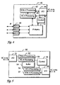
- Figur 4:
- ein Blockdiagramm von einem IP-Router als Peripheriegerät für ein synchrones Nachrichtenübertragungsnetz und
- Figur 5:
- ein Blockdiagramm von einem Multiplexer des Nachrichtenübertragungsnetzes, der die Umwandlung durchführt.
- Figures 1 to 3:
- An IP router which is connected to a synchronous digital communications network and generates a synchronous message signal with seamlessly chained multiplex units, the seamless concatenation in a multiplexer of the communications network being converted into virtual concatenation,
- Figure 4:
- a block diagram of an IP router as a peripheral device for a synchronous communication network and
- Figure 5:
- a block diagram of a multiplexer of the communications network that performs the conversion.
Ein Grundgedanke der Erfindung liegt darin, im Peripheriegerät eine nahtlose Verkettung von Multiplexeinheiten zu erzeugen, jedoch nur einen Teil der verketteten Multiplexeinheiten für Nutzlast zu verwenden und den übrigen Teil frei zu lassen oder mit einem Füllmuster aufzufüllen. Ein weiterer Grundgedanke der Erfindung besteht darin, daß der Multiplexer am Übergang zu einem synchronen digitalen Nachrichtenübertragungsnetzes eine Umwandlung der nahtlosen Verkettung in eine virtuelle Verkettung durchführt und bei der Umwandlung solche Multiplexeinheiten wegläßt, die nicht mit Nutzlast gefüllt sind. Somit wird eine Anpassung der Anzahl von verketteten Multiplexeinheiten an die tatsächlich benötigte Bandbreite bei der Umwandlung von nahtloser Verkettung in virtuelle Verkettung durchgeführt.A basic idea of the invention is to provide seamless peripheral equipment Generate concatenation of multiplex units, but only a part of the concatenated multiplex units to use for payload and the rest leave blank or fill up with a fill pattern. Another The basic idea of the invention is that the multiplexer on Transition to a synchronous digital communications network Performs the seamless chaining to virtual chaining and omits those multiplex units that are not included in the conversion Payload are filled. Thus an adjustment of the number of chained Multiplex units to the bandwidth actually required at the Conversion from seamless chaining to virtual chaining performed.
Bei der Erläuterung des erfindungsgemäßen Übertragungsverfahrens wird der Übersichtlichkeit halber im folgenden nur eine Übertragungsrichtung betrachtet. Gleichwohl kann die Übertragung auch bidirektional erfolgen.In the explanation of the transmission method according to the invention For the sake of clarity, only one direction of transmission in the following considered. Nevertheless, the transmission can also be bidirectional.
In Figur 1 ist dorgestellt, wie von einem ersten Peripheriegerät 10 eine
Nutzlast über ein synchrones digitales Nachrichtenübertragungsnetz SDH zu
einem zweiten Peripheriegerät 16 übertragen wird. Die Peripheriegeräte sind
IP-Router und die Nutzlast besteht aus Datenpaketen, die nach dem Internet-Protokoll
strukturiert sind. In dem ersten IP-Router 10 wird ein synchrones
Nachrichtensignal 11 erzeugt. Es handelt sich dabei um ein
rahmenstrukturiertes Multiplexsignal vom Typ STM-4. Der STM-4-Rahmen
besteht aus vier byteweise verschachtelten Transportmodulen vom Typ STM-1.
Jeder der vier STM-1-Rahmen enthält jeweils eine Multiplexeinheit VC-4. Die
vier Multiplexeinheiten VC-4 sind nahtlos verkettet. Dadurch ergibt sich eine
maximale Nutzlast von 4 x 149 Mbit = 596 Mbit, die von dem IP-Router mit
den zu übertragenden IP-Paketen gefüllt wird. Um die IP-Pakete in die
Multiplexeinheiten zu verpacken kann z.B. das PPP-Protokoll verwendet
werden, das von IETF (Internet Engineering Task Force) festgelegt wurde. Die
beschriebene Art der Verkettung wird als VC-4-4c bezeichnet. Die IP-Router
10, 16 sind Teil eines Datennetzwerkes und nutzen das synchrone digitale
Nachrichtenübertragungsnetz SDH als Backbone-Netz.FIG. 1 shows how one from a first
Von dem ersten IP-Router 10 gelangt das synchrone Nachrichtensignal 11 zu
einem Multiplexer 12 des synchronen digitalen Nachrichtennetzes SDH. Dieser
stellt den Übergang vom synchronen Nachrichtennetz SDH zum Datennetz
dar. In dem Multiplexer 12 wird die nahtlose Verkettung der vier
Multiplexeinheiten VC-4 in eine virtuelle Verkettung umgewandelt. Dazu wird
wie eingangs erwähnt jeder der vier Multiplexeinheiten mit einem eigenen
Zeiger versehen und es wird eine Kennzeichnung im Kopfbereich (Overhead)
der Multiplexeinheiten eingefügt, die auf die Verkettung hinweist. Die vier
virtuell verketteten Multiplexeinheiten VC-4 können nun unabhängig von
einander in separaten kleineren oder gemeinsamen größeren
Transportmodulen durch das Nachrichtennetz SDH übertragen werden. Im
Ausführungsbeispiel ist angedeutet, daß jede der vier virtuell verketteten
Multiplexeinheiten über einen eigenen Pfad 13a-d übertragen wird. Die
virtuelle Verkettung wird als VC-4-4v bezeichnet.The
Die virtuell verketteten Multiplexeinheiten werden nun durch das
Nachrichtenübertragungsnetz SDH zur Datensenke, einem zweiten Multiplexer
14 übertragen. Dieser wandelt die virtuelle Verkettung wieder in eine nahtlose
Verkettung um und überträgt die vier nahtlos verketteten Multiplexeinheiten in
einem zu STM-4-Rahmen strukturierten Nachrichtensignal 15 zu dem zweiten
IP-Router 16.The virtual concatenated multiplex units are now replaced by the
SDH data transmission network for data sink, a
Bei den Multiplexern kann es sich um sogenannte Add/Drop-Multiplexer oder um Terminalmultiplexer handeln, die einzelne oder auch alle Pfade terminieren, die in den empfangenen rahmenstrukturierten Multiplexsignalen enthalten sind.The multiplexers can be so-called add / drop multiplexers or are terminal multiplexers, the individual or all paths terminate that in the received frame structured multiplex signals are included.
Zu Zeiten hoher Auslastung des Datennetzes sind alle Multiplexeinheiten voll
mit IP-Paketen bepackt und die beschriebene Datenübertragung über das als
Backbone-Netz fungierende synchrone digitale Nachrichtenübertragungsnetz
ist schnell und effizient. Bei der Paketdatenübertragung treten jedoch auch
längere Zeitabschnitte auf, in denen nicht ausreichend zu übertragende IP-Pakete
anfallen, um alle vier Multiplexeinheiten voll zu bepacken.
Erfindungsgemäß werden in dem IP-Router 10 dann nur ein Teil der
Multiplexeinheiten für den Transport von Datenpaketen verwendet und die
übrigen Multiplexeinheiten bleiben leer oder werden mit einem Füllmuster
gefüllt.At times of high utilization of the data network, all multiplex units are full
packed with IP packets and the data transmission described as
Backbone network acting synchronous digital communication network
is fast and efficient. However, packet data transmission also occurs
Longer periods of time in which the IP packets are insufficient to transmit
to fully load all four multiplex units.
According to the invention, only part of the
Diese Situation ist in Figur 2 dargestellt. Der IP-Router 10 bepackt nur drei der
vier verketteten Multiplexeinheiten VC-4-4c. Die vierte Multiplexeinheit bleibt
leer. Das Nachrichtensignal 11, das der IP-Router 10 an den Multiplexer 12
sendet, weist jedoch nach wie vor dieselbe Struktur auf, nämlich einen STM-4-Rahmen
mit vier nahtlos verketteten Multiplexeinheiten VC-4-4c. In dem
Multiplexer 12 wird die nahtlose Verkettung in die virtuelle Verkettung
umgewandelt. Dabei wird die vierte, mit Datenpoketen nicht bepackte
Multiplexeinheit weggelassen. Es entsteht also eine virtuelle Verkettung aus
drei Multiplexeinheiten VC-4-3v, die über die Pfade 13a-c zu dem zweiten
Multiplexer 14 übertragen wird. Dort wird die virtuelle Verkettung wieder zu
einer nahtlosen Verkettung umgewandelt und mit einer leeren Multiplexeinheit
ergänzt zu VC-4-4c an den zweiten IP-Router 16 übertragen.This situation is shown in Figure 2. The
Da der STM-4-Rahmen aus vier byteweise verschachtelten STM-1-Rahmen besteht, ist es äußerst einfach für den IP-Router, eine Multiplexeinheit frei zu lassen: Er fügt einfach nach drei Bytes jeweils ein Füllbyte (z.B. hex00) ein. Der Multiplexer benötigt für die Umwandlung der nahtlosen Verkettung von vier Multiplexeinheiten in eine virtuelle Verkettung von drei Multiplexeinheiten die Information, das und welche der vier Multiplexeinheiten entfallen soll. Eine Möglichkeit besteht darin, daß der IP-Router die Information bereitstellt. Dies kann entweder über einen dedizierten Steuerkanal im Kopfbereich der Multiplexeinheiten oder Transportmodule oder über ein übergeordnetes Netzwerkmanagementsystem erfolgen. Eine andere Möglichkeit besteht darin, daß in dem Multiplexer selbsttätig z.B. anhand des Füllmusters oder anhand fehlender IP-Header erkannt wird, daß eine der Multiplexeinheiten nicht mit IP-Paketen bepackt ist und diese freie Multiplexeinheit bei der Umwandlung dann weggelassen wird. Entweder kann die selbsttätige Erkennung durch Überwachen der Nutzlast in dem Multiplexer ausgeführt werden, oder auch dadurch daß unbenutzte Multiplexeinheiten von dem IP-Router im Kopfbereich markiert werden.Because the STM-4 frame consists of four STM-1 frames nested in bytes , it is extremely easy for the IP router to free a multiplex unit leave: He simply inserts a filler byte (e.g. hex00) after three bytes. The Multiplexer needed to convert seamless chaining of four Multiplex units in a virtual chain of three multiplex units Information which and which of the four multiplex units should be omitted. A One possibility is that the IP router provides the information. This can either be via a dedicated control channel in the head area of the Multiplex units or transport modules or via a higher-level Network management system. Another option is that in the multiplexer automatically e.g. based on the filling pattern or based on missing IP header is recognized that one of the multiplex units is not with IP packets are packed and this free multiplex unit during conversion then left out. Either the automatic detection can Monitor the payload in the multiplexer, or else in that unused multiplex units from the IP router in the header be marked.
Bei Verwendung einer Variante des PPP-Protokolls (Point-to-Point Protocol, IETF) oder eine ähnlichen Variante, werden IP-Pakete in HDLC-Frames eingerahmt. Bytes zwischen den HDLC-Frames sind Füllmuster.When using a variant of the PPP protocol (Point-to-Point Protocol, IETF) or a similar variant, IP packets are in HDLC frames framed. Bytes between the HDLC frames are fill patterns.
In Figur 3 ist nun gezeigt, daß nur zwei der vier Multiplexeinheiten zum Transport von IP-Paketen verwendet werden und daß der Multiplexer bei der Umwandlung zu virtueller Verkettung die zwei unbenutzten Multiplexeinheiten wegläßt und lediglich zwei der ursprünglich vier Multiplexeinheiten über das Nachrichtenübertragungsnetz SDH überträgt. Diese Verkettung wird dann als VC-4-2v bezeichnet. Ähnlich kann die nahtlose Verkettung auch durch weglassen dreier leerer Multiplexeinheiten in eine einzige Multiplexeinheit überführt werden.In Figure 3 it is now shown that only two of the four multiplex units for Transport of IP packets are used and that the multiplexer at Conversion to virtual concatenation the two unused multiplex units omits and only two of the originally four multiplex units via the SDH communications network. This chaining is then called VC-4-2v designated. Similarly, seamless chaining can also be done by omit three empty multiplex units into a single multiplex unit be transferred.
Die Erfindung ist nicht beschränkt auf eine Verkettung virtueller Container vom Typ VC-4. Ebenso können beispielsweise Container vom Typ VC-12 mit einer Nutzlast von 2 Mbit verwendet werden. Möglich ist auch der Einsatz in SONET-Systemen mit Containern vom Typ VC-3 oder VC-11 (VT-1,5). Ebenso sind größere Verkettungen von beispielsweise 8, 16 oder 64 Containern möglich.The invention is not restricted to a chaining of virtual containers from Type VC-4. VC-12 containers with a Payload of 2 Mbit can be used. Use in SONET systems with containers of type VC-3 or VC-11 (VT-1.5). As well are larger concatenations of 8, 16 or 64 containers, for example possible.
Die Umwandlung in eine kleiner Anzahl von virtuell verketteten Multiplexeinheiten kann auch vordefiniert sein, so daß z.B. zu bestimmten Zeiten die volle Bandbreite aller Multiplexeinheiten zur Verfügung steht, zu anderen Zeiten jedoch nur eine reduzierte Kapazität. Beispielsweise kann von 8:00 bis 10:00 und von 16:00 bis 18:00 Uhr eine Verkettung von drei VC-4 gewählt werden, in Hauptzeiten von 10:00-16:00 Uhr eine virtuelle Verkettung von allen vier VC-4 und in Nebenzeiten von 18:00 bis 8:00 Uhr von nur ein oder zwei VC-4. So kann die tatsächlich übertragene Nutzlast an die statistische Ausnutzung des Datennetzes angepaßt werden. Alternativ kann auch eine dynamische Anpassung nach einem ermittelten Verkehrsaufkommen etwa alle 10 min. erfolgen. Wird eine Voreinstellung verwendet, so entfällt die Übermittlung der Information, welche Multiplexeinheiten aktuell für Datenpakete genutzt werden vom IP-Router an den Multiplexer.The conversion to a small number of virtually chained Multiplex units can also be predefined so that e.g. To determine Times the full bandwidth of all multiplex units is available, too other times only a reduced capacity. For example, from 8:00 to 10:00 and from 16:00 to 18:00 a chain of three VC-4 be selected, a virtual one at peak times from 10 a.m. to 4 p.m. Chaining of all four VC-4 and in non-productive times from 6:00 p.m. to 8:00 a.m. from just one or two VC-4. So the actually transmitted payload can the statistical utilization of the data network can be adjusted. Alternatively, you can also a dynamic adjustment after a determined Traffic around every 10 minutes. respectively. Will be a preset used, the transmission of the information is omitted Multiplex units currently used for data packets are used by the IP router the multiplexer.
Auf diese Weise ergibt sich ein erheblicher Vorteil für den Betreiber des Datennetzes, da er Gebühren nur für die tatsächlich übertragenen Multiplexeinheiten an den Betreiber des synchronen Nachrichtenübertragungsnetzes, das er als Backbone nutzt, entrichten muß.In this way, there is a considerable advantage for the operator of the Data network since it charges only for the actually transmitted Multiplex units to the operator of the synchronous Communication network that he uses as a backbone must pay.
Ein weiterer bevorzugter Einsatz des erfindungsgemäßen Verfahrens ist zur Übertragung von Datenpaketen, die nach dem Protokoll für asynchronen Transportmodus (ATM) strukturiert sind. Als Peripheriegerät dient in diesem Fall ein ATM-Switch, der die aus ATM-Zellen bestehende Nutzlast in nahtlos verkettete Multiplexeinheiten verpackt und an den Multiplexer des synchronen Nachrichtennetzes überträgt.Another preferred use of the method according to the invention is for Transmission of data packets according to the protocol for asynchronous Transport mode (ATM) are structured. This serves as a peripheral device Case an ATM switch that seamlessly transforms the payload consisting of ATM cells concatenated multiplex units packed and to the multiplexer of the synchronous Transmits news network.
Ein weiterer bevorzugter Einsatz des erfindungsgemäßen Verfahrens ist zur Übertragung von Datenpaketen, die nach dem Protokoll für Ethernet strukturiert sind. Die Ethernet-Frames sind in HDLC-Frames eingerahmt und werden transparent in verketteten SDH-Containern transportiert. Zwischen den HDLC-Frames kann ein Füllmuster eingefügt werden, das bei der erfindungsgemäßen Kompression entfernt wird, um so die Anzahl der verketteten Container zu reduzieren.Another preferred use of the method according to the invention is for Transmission of data packets according to the protocol for Ethernet are structured. The Ethernet frames are framed in HDLC frames and are transported transparently in linked SDH containers. Between A fill pattern can be inserted in HDLC frames Compression according to the invention is removed, so the number of to reduce linked containers.
Bislang wurde nur eine Übertragungsrichtung berücksichtigt. Bei bidirektionalen Verbindungen ergibt sich jedoch ein weiterer vorteilhafter Einsatzbereich. Bei klassischen Gesprächsverbindungen war stets in beiden Richtungen (,upstream' und ,downstream') die gleiche Übertragungsrate erforderlich. Dies ändert sich jedoch bei Datenübertragung. So wird erwartet, daß in zukünftigen Datennetzen der Verkehr stark asymmetrisch ausfällt wie z.B. bei ADSL (Asymmetrical Digital Subscriber Line). Die erfindungsgemäße Kompression kann daher vorteilhaft in nur einer Übertragungsrichtung eingesetzt werden, während in der anderen Übertragungsrichtung die volle Kapazität aller verketteten Multiplexeinheiten zur Verfügung steht. Hierbei ist die erfindungsgemäße Kompression von besonderem Vorteil, da in der Regel die physikalischen Schnittstellen der Peripheriegeräte die gleiche Bandbreite in beide Richtungen anbieten. Somit kann die Übertragungskapazität auch bei solchen symmetrischen Schnittstellen an ein asymmetrisches Verkehrsaufkommen angepaßt werden.So far, only one direction of transmission has been taken into account. at However, bidirectional connections result in a further advantageous one Application. With classic conversation connections was always in both Directions (upstream and downstream) have the same transmission rate required. However, this changes with data transmission. So it is expected that in future data networks the traffic will be very asymmetrical like e.g. at ADSL (Asymmetrical Digital Subscriber Line). The invention Compression can therefore be advantageous in only one direction of transmission be used while in the other direction of transmission the full Capacity of all chained multiplex units is available. Here is the compression according to the invention is particularly advantageous since, as a rule the physical interfaces of the peripheral devices in the same bandwidth offer both directions. Thus, the transmission capacity can also such symmetrical interfaces to an asymmetrical Traffic volume can be adjusted.
Der IP-Router 40 des Ausführungsbeispieles ist in Figur 4 in einem
Blockdiagramm schematisch gezeigt. Er weist mehrere LAN-Schnittstellen 45
(LAN: local area network), die entsprechend dem Standard für Ethernet IEEE
802.3 nach einem asynchronen Übertragungsverfahren mit
Kollisionserkennung arbeiten. An jeder der LAN-Schnittstellen ist ein lokales
Datennetz angeschlossen und der IP-Router 40 empfängt jeweils Datenpakete
IP, die nach dem Internetprotokoll strukturiert sind. Die Datenpakete werden
von den LAN-Schnittstellen an eine IP-Matrix 41 geleitet. Diese entscheidet
anhand der Zieladresse jedes Datenpaketes, wohin es gesendet werden soll.
Datenpakete, die für ein anderes an den IP-Router angeschlossenes Datennetz
bestimmt sind, werden an der entsprechenden LAN-Schnittstelle gesendet. Die
übrigen Datenpakete, d.h. die Datenpakete, die nicht für eines der an den
LAN-Schnittstellen angeschlossenen lokalen Datennetze bestimmt sind,
werden von der IP-Matrix 41 zu einer Verarbeitungseinheit 42 geschaltet. Dort
werden vier Multiplexeinheiten vom Typ VC-4 gebildet und mit den
Datenpaketen bepackt. Die bepackten Multiplexeinheiten werden an eine
Verarbeitungseinheit 43 für Transportmodule vom Typ STM-4 weitergeleitet,
wo durch nahtloses Verketten und byteweises Verschachteln der vier
Multiplexeinheiten ein rahmenstrukturiertes Multiplexsignal vom Type STM-4,
VC-4-4c gebildet wird, das dann an der Schnittstelle I/O 44 als synchrones
Nachrichtensignal gesendet wird. In der STM-4-Verarbeitungseinheit wird
auch ein Zeiger bestimmt und in den Kopfbereich der Transportmodule
geschrieben, der auf den Beginn der ersten Multiplexeinheit zeigt. Bei der
Schnittstelle I/O 44 handelt es sich um eine optische Schnittstelle. The
Der IP-Router 40 weist weiterhin eine Steuerungseinrichtung 46 auf, die mit
der IP-Matrix 41 und der Verarbeitungseinheit 42 für Multiplexeinheiten VC-4
verbunden ist. In der IP-Matrix 41 wird ein aktuelles Verkehrsaufkommen
bestimmt und an die Steuerungseinrichtung 46 geleitet. Diese entscheidet
daraufhin in regelmäßigen Abständen entsprechend dem
Verkehrsaufkommen oder wahlweise auch nach einem vorgegebenen
Zeitplan, wieviele der vier Multiplexeinheiten mit Datenpaketen bepackt
werden sollen und teilt dies der VC-4-Verarbeitungseinrichtung 42 mit.
Dementsprechend werden in der Verarbeitungseinrichtung 42 nur die
ausgewählten Multiplexeinheiten bepackt, die übrigen werden mit einem
Füllmuster aufgefüllt. In der Verarbeitungseinheit 42 werden die nicht
bepackten Multiplexeinheiten im Kopfbereich markiert. Hierfür kann eines der
für proprietäre Zwecke reservierten Overhead-Bytes verwendet werden.The
Der IP-Router kann auch so konfiguriert sein, daß stets nur zwei oder drei der
vier nahtlos verketteten Multiplexeinheiten mit Nutzdaten gefüllt werden. In
diesem Fall ist eine Steuerungseinrichtung 46 nicht notwendig. Die
Verarbeitungseinheit 42 ist dann so eingestellt, daß nur die vorbestimmten
Multiplexeinheiten mit IP-Paketen bepackt werden und die übrigen stets frei
bleiben.The IP router can also be configured so that only two or three of the
four seamlessly linked multiplex units can be filled with user data. In
In this case, a
Aus dem Beispiel wird deutlich, daß die IP-Matrix 41 eine Filterfunktion
ausführt, da nur solche IP-Pakete von der Matrix zu der VC-4-Verarbeitungseinheit
geleitet werden, die über das synchrone digitale
Nachrichtenübertragungsnetz zu anderen lokolen Datennetzen transportiert
werden sollen, die nicht direkt an einer LAN-Schnittstelle des IP-Routers
angeschlossen sind. Die IP-Matrix 41 kann auch eine weitere Filterfunktion
ausführen, indem sie Datenpakete, deren Zustellung über das synchrone
digitale Nachrichtenübertragungsnetz nicht möglich ist, verwirft oder mit einer
entsprechenden Fehlermeldung an den Absender zurückschickt. Eine solche
Filterfunktion kann durch entsprechende Einträge in der Routing-Tabelle der
IP-Matrix ausgeführt werden. So können nicht existierende oder aufgrund
eines Konfigurationsfehlers fehlerhafte IP-Adressen herausgefiltert werden.
Zudem kann auf diese Weise eine Schutzfunktion in der Art eines Firewalls
realisiert werden.From the example it is clear that the
Der Multiplexer 50, der das synchrone Nachrichtensignal empfängt, die
nahtlose Verkettung in virtuelle Verkettung umwandelt und die
Multiplexeinheiten über das synchrone Nachrichtenübertragungssystem
überträgt ist, in Figur 5 schematisch dargestellt. Er empfängt an einer ersten
Schnittstelle I/O 51 das synchrone Nachrichtensignal von dem
Peripheriegerät. In einer ersten Verarbeitungseinheit 52 für Transportmodule
vom Typ STM-4 wird die byteweise Verschachtelung aufgelöst und der Zeiger
auf die erste Multiplexeinheit ausgewertet. Entsprechend dem Zeigerwert
werden die vier verketteten Multiplexeinheiten ausgelesen und an eine erste
Verarbeitungseinheit 53 für Multiplexeinheiten vom Typ VC-4 geleitet. Dort
wird der Kopfbereich der einzelnen Multiplexeinheiten ausgewertet. Eine
Markierung, die daraufhinweist, daß die entsprechende Multiplexeinheit nicht
mit Nutzdaten gefüllt ist, wird erkannt und die entsprechende Multiplexeinheit
daraufhin ausgesondert. Die Information darüber wird auch an eine
Steuerungseinrichtung 55 weitergeleitet. Die übrigen Multiplexeinheiten
werden in einem Pufferspeicher 54 zwischengespeichert. Von dort aus werden
sie von einer zweiten Verarbeitungseinheit 56 für Multiplexeinheiten vom Typ
VC-4 wieder ausgelesen. Von der Steuerungseinheit erhält die zweite VC-4-Verarbeitungseinheit
56 die Information, welche und wieviele
Multiplexeinheiten zu einer virtuellen Verkettung zusammengefügt werden
sollen. Die virtuelle Verkettung erfolgt durch eine entsprechende
Kennzeichnung im Kopfbereich der Multiplexeinheiten. Dazu wird derzeit das
H4-Byte verwendet.The multiplexer 50, which receives the synchronous message signal, the
converts seamless chaining into virtual chaining and that
Multiplex units via the synchronous message transmission system
is shown schematically in Figure 5. He receives on a first
Interface I /
Die verketteten Multiplexeinheiten werden dann einer zweiten
Verarbeitungseinheit 57 für Transportmodule vom Typ STM-4 zugeleitet, wo
sie in jeweils einen eigenen STM-1-Rahmen verpackt werden. Die STM-1-Rahmen
werden byteweise verschachtelt, um ein aus Transportmodulen vom
Type STM-4 bestehendes synchrones Nachrichtensignal zu bilden, das dann
an einer zweiten Schnittstelle I/O 58 in dos synchrone digitale
Nachrichtenübertragungsnetz gesendet wird. Die zweite STM-4-Verarbeitungseinheit
56 bestimmt auch einen Zeiger für jede der
Multiplexeinheiten, der auf den Beginn der jeweiligen Multiplexeinheit zeigt
und in den Kopfbereich der jeweiligen STM-1-Transportmodule geschrieben
wird.The concatenated multiplex units then become a second
Im Ausführungsbeispiel enthält das Eingangssignal des Multiplexers eine nahtlose Verkettung VC-4-4c aus vier Multiplexeinheiten vom Type VC-4. Eine der vier Multiplexeinheiten ist jedoch beispielsweise nicht für den Transport von Nutzdaten genutzt und als solche im Kopfbereich gekennzeichnet. In der ersten VC-4-Verarbeitungseinheit wird diese Multiplexeinheit ausgesondert. Über die Steuerungseinrichtung wird die Information, daß die übrigen drei Multiplexeinheiten virtuell verkettet werden sollen an die zweite VC-4-Verarbeitungseinheit weitergeleitet. Diese führt die entsprechende Verkettung durch. So wird ein Ausgangssignal gebildet, daß eine virtuelle Verkettung VC-4-3v aus drei Multiplexeinheiten VC-4 enthält. Die übrige Übertragungskapazität kann für zusätzlichen Verkehr, beispielsweise für ein Bündel von Telefonverbindungen genutzt werden. Vorteilhafterweise teilt der Multiplexer dem Netzwerkmanagementsystem mit, wieviele Multiplexeinheiten die virtuelle Verkettung umfaßt, damit über das Netzwerkmanagementsystem die freie Übertragungskapazität für andere Zwecke vergeben werden kann.In the exemplary embodiment, the input signal of the multiplexer contains one Seamless interlinking VC-4-4c from four multiplex units of the type VC-4. A however, the four multiplex units are not for transport, for example used by user data and identified as such in the header area. In the This multiplex unit is discarded in the first VC-4 processing unit. The information that the remaining three Multiplex units are to be virtually chained to the second VC-4 processing unit forwarded. This leads the corresponding chaining by. So an output signal is formed that a virtual chain VC-4-3v contains three multiplex units VC-4. The rest Transmission capacity can be used for additional traffic, for example for a Bundle of telephone connections can be used. Advantageously, the Multiplexer the network management system with how many multiplex units the virtual chain includes, therefore, via the network management system the free transmission capacity can be allocated for other purposes.
Anstelle ungenutzte Multiplexeinheiten der nahtlosen Verkettung im Kopfbereich zu markieren, kann die Information, welche der verketteten Multiplexeinheiten für den Transport von Nutzdaten verwendet werden, auch über das Netzwerkmanagementsystem von dem Peripheriegerät zu dem Multiplexer weitergeleitet werden. Alternativ findet in dem Multiplexer eine Auswertung der in jeder Multiplexeinheit enthaltenen Nutzlast statt, um zu ermitteln, welche der Multiplexeinheiten mit Nutzdaten bepackt sind und welche ungenutzt sind.Instead of unused multiplex units of seamless chaining in the Marking the header area can indicate which of the chained Multiplex units are used for the transport of user data, too via the network management system from the peripheral device to the Multiplexers are forwarded. Alternatively, one can be found in the multiplexer Evaluation of the payload contained in each multiplex unit takes place in order to determine which of the multiplex units are packed with user data and which are unused.
Bei dem Multiplexer kann es sich um einen Terminalmultiplexer, einen Add/Drop-Multiplexer oder auch um einen digitalen Crossconnect handeln. Er kann auch weiter Baugruppen wie eine Zeit- und Raumschaltmatrix für Multiplexeinheiten und weitere Schnittstellen zum Nachrichtenübertragungsnetz aufweisen. Die einzelnen Multiplexeinheiten der virtuellen Verkettung können in diesem Fall über verschiedene Schnittstellen und verschiedene Pfade zum Zielnetzelement übertragen werden. Anstelle von Multiplexeinheiten vom Type VC-4 können auch andere, kleinere Untereinheiten aus der Multiplexhierarchie des Übertragungssystems eingesetzt werden, wie beispielsweise VC-12 oder VC-3.The multiplexer can be a terminal multiplexer, a Add / drop multiplexer or a digital cross-connect. He can also further assemblies such as a time and space switching matrix for Multiplex units and other interfaces to the Have communication network. The individual multiplex units of the In this case, virtual chaining can be done via different interfaces and different paths are transmitted to the target network element. Instead of Type VC-4 multiplex units can also do other, smaller ones Sub-units from the multiplex hierarchy of the transmission system are used, such as VC-12 or VC-3.
Eine alternative Ausführungsform des Peripheriegerätes ist ein ATM-Switch. Dieser ist ähnlich aufgebaut wie der IP-Router in Figur 4, besitzt jedoch anstelle der LAN-Schnittstellen entsprechende ATM-Schnittstellen und anstelle der IP-Matrix eine Schaltmatrix für ATM-Zellen.An alternative embodiment of the peripheral device is an ATM switch. This is constructed similarly to the IP router in Figure 4, but has corresponding ATM interfaces instead of the LAN interfaces and instead the IP matrix is a switching matrix for ATM cells.
Claims (8)
- Method of transmitting payload data via a synchronous digital message transmission network (SDH), the payload data being packed into multiplex units, multiple multiplex units (VC-4-4c) being contiguously concatenated, the contiguously concatenated multiplex units (VC-4-4c) being transmitted in a common transport module (STM-4), and the contiguous concatenation of multiplex units (VC-4-4c) being converted into a virtual concatenation of multiplex units (VC-4-4v, VC-4-3v, VC-4-2v, VC-4-Nv),
characterized in that
at least one of the multiplex units is not filled with payload data, and in the conversion those multiplex units which are not filled with payload data are omitted. - Method according to Claim 1, in which the payload data are data packets which are structured according to the Internet protocol, the data packets being packed into the multiplex units in an IP router (10; 40), the contiguous concatenation (VC-4-4c) being converted into the virtual concatenation (VC-4-Nv) in a multiplexer (12; 50) of the synchronous digital message transmission network (SDH), and the IP router (10; 40) informing the multiplexer (12; 50) about which of the concatenated multiplex units are filled with data packets.
- Method according to Claim 1, the payload data being data packets which are structured according to the protocol for Asynchronous Transport Mode, the data packets being packed into the multiplex units in an ATM switch, the contiguous concatenation being converted into the virtual concatenation in a multiplexer (12; 50) of the synchronous digital message transmission network (SDH), and the ATM switch informing the multiplexer (12; 50) about which of the concatenated multiplex units are filled with data packets.
- Method according to Claim 1, the virtual concatenation then being converted back into a contiguous concatenation, and the omitted multiplex units being replenished by empty multiplex units.
- Multiplexer (12; 50) for a synchronous digital message transmission network (SDH),characterized in thatwith a first interface (51) to receive a first message signal which is structured into transport modules (STM-4), containing multiple contiguously concatenated multiplex units (VC-4-4c) containing payload data to be transmitted,with a conversion unit (53, 54, 55, 56) to convert the contiguous concatenation (VC-4-4c) into a virtual concatenation of the multiplex units (VC-4-4v, VC-4-3v, VC-4-2v, VC-4-Nv), andwith at least one second interface (58) to send at least one second message signal which is structured into transport modules, and in which the virtually concatenated multiplex units (VC-4-4v, VC-4-3v, VC-4-2v, VC-4-Nv) are contained,
the conversion unit (53, 54, 55, 56) is adapted, for the case that at least one of the contiguously concatenated multiplex units is not filled with payload data, to omit those multiplex units which are not filled with payload data in the conversion of the contiguous concatenation (VC-4-4c) into the virtual concatenation (VC-4-4v, VC-4-3v, VC-4-2v, VC-4-Nv). - Peripheral device (10,40) to transmit payload data via a synchronous digital message transmission network, the peripheral device (10; 40) having a signal generation device (43) to generate a message signal which is structured into transport modules, containing multiple contiguously concatenated multiplex units (VC-4-4c) containing payload data to be transmitted, and a multiplexing device (42) to pack the payload data into the multiplex units,
characterized in that
the multiplexing device (42) is suitable for always filling only selected multiplex units of the contiguous concatenation (VC-4-4c) with payload data, and always not filling at least one multiplex unit which has not been selected with payload data. - Peripheral device (10, 40) according to Claim 6, with a control device (46), which is in a form to decide how many of the multiplex units are to be filled with data packets, and to control the multiplexing device (42) in such a way that it fills only the thus selected multiplex units with payload data, whereas the others are not filled with payload data.
- Peripheral device (10, 40) according to Claim 6, the multiplexing device (42) being configurable in such a way that it is possible to predefine which multiplex units are selected to be filled with payload data, and which are always not filled with payload data.
Applications Claiming Priority (2)
| Application Number | Priority Date | Filing Date | Title |
|---|---|---|---|
| DE19932739A DE19932739A1 (en) | 1999-07-14 | 1999-07-14 | Conversion from seamless chaining to virtual chaining in a synchronous digital communications network |
| DE19932739 | 1999-07-14 |
Publications (3)
| Publication Number | Publication Date |
|---|---|
| EP1069718A2 EP1069718A2 (en) | 2001-01-17 |
| EP1069718A3 EP1069718A3 (en) | 2003-03-19 |
| EP1069718B1 true EP1069718B1 (en) | 2003-11-12 |
Family
ID=7914634
Family Applications (1)
| Application Number | Title | Priority Date | Filing Date |
|---|---|---|---|
| EP00440200A Expired - Lifetime EP1069718B1 (en) | 1999-07-14 | 2000-06-30 | Conversion of seamless concatenation into virtual concatenation in a synchronous digital data transmission network |
Country Status (5)
| Country | Link |
|---|---|
| US (2) | US6842455B1 (en) |
| EP (1) | EP1069718B1 (en) |
| JP (1) | JP4423759B2 (en) |
| AT (1) | ATE254365T1 (en) |
| DE (2) | DE19932739A1 (en) |
Families Citing this family (18)
| Publication number | Priority date | Publication date | Assignee | Title |
|---|---|---|---|---|
| EP1158710B1 (en) * | 2000-05-26 | 2003-11-05 | Alcatel | Method for transmitting of synchronous transport modules over a synchronous transport network |
| US7260099B1 (en) * | 2000-07-14 | 2007-08-21 | Nortel Networks Limited | Processing of arbitrarily formatted client signals to achieve compatibility with existing transport networks |
| DE10047510A1 (en) * | 2000-09-26 | 2002-04-11 | Alcatel Sa | Transport module for SDH / SONET |
| EP1248399A1 (en) * | 2001-04-02 | 2002-10-09 | Lucent Technologies Inc. | Transporting a gigabit per second datastream over a SONET/SDH network |
| CA2356572A1 (en) * | 2001-08-30 | 2003-02-28 | Heng Liao | Transmit virtual concatenation processor |
| JP2003078496A (en) * | 2001-08-31 | 2003-03-14 | Fujitsu Ltd | Path control method |
| US20030074449A1 (en) * | 2001-10-12 | 2003-04-17 | Rory Smith | Bandwidth allocation in a synchronous transmission network for packet oriented signals |
| US8543681B2 (en) * | 2001-10-15 | 2013-09-24 | Volli Polymer Gmbh Llc | Network topology discovery systems and methods |
| US8868715B2 (en) * | 2001-10-15 | 2014-10-21 | Volli Polymer Gmbh Llc | Report generation and visualization systems and methods and their use in testing frameworks for determining suitability of a network for target applications |
| CA2416659C (en) * | 2002-01-22 | 2007-01-16 | Nippon Telegraph And Telephone Corporation | Capacity variable link apparatus and capacity variable link setting method |
| EP1367751A1 (en) * | 2002-05-28 | 2003-12-03 | Alcatel | Fallback in transmission of data signals through a synchronous digital network using virtual concatenated containers |
| US20050147106A1 (en) * | 2002-09-26 | 2005-07-07 | Kazumasa Sonoda | Transmission system |
| DE10245638A1 (en) * | 2002-09-30 | 2004-04-15 | Siemens Ag | Method for the transmission of data signals by means of virtually linked partial signals over synchronous data networks |
| US8204085B1 (en) * | 2003-12-15 | 2012-06-19 | Ciena Corporation | Virtual concatenation for parallel data streams |
| US7298744B1 (en) * | 2003-12-30 | 2007-11-20 | Intel Corporation | Method and apparatus for centralized processing of contiguously and virtually concatenated payloads |
| JP2008538456A (en) * | 2005-01-21 | 2008-10-23 | アール・エム・アイ コーポレーション | Network system and central authentication service execution method |
| JP2010273016A (en) * | 2009-05-20 | 2010-12-02 | Nec Corp | Data transmission system, and data transmission method and device |
| WO2014147743A1 (en) | 2013-03-19 | 2014-09-25 | 富士通株式会社 | Transmission device, transmission system, and transmission method |
Family Cites Families (9)
| Publication number | Priority date | Publication date | Assignee | Title |
|---|---|---|---|---|
| US4513884A (en) | 1982-04-05 | 1985-04-30 | Enviro-Spray Systems, Inc. | Dispensing system and a refill pouch |
| FI90297C (en) * | 1992-04-02 | 1994-01-10 | Nokia Telecommunications Oy | Network interface procedure and network interface for a digital data network |
| GB9604619D0 (en) * | 1996-03-04 | 1996-05-01 | Plessey Telecomm | Combined multiplexer |
| US5765640A (en) * | 1996-03-07 | 1998-06-16 | Baker Hughes Incorporated | Multipurpose tool |
| US5764645A (en) * | 1996-06-12 | 1998-06-09 | Microsoft Corporation | IP/ATM network adaptation |
| GB9718831D0 (en) * | 1997-09-05 | 1997-11-12 | Plessey Telecomm | Data transmission in an sdh network |
| US6014708A (en) * | 1998-02-19 | 2000-01-11 | Alcatel | Adaptor and method for mapping a fast ethernet payload input signal to a synchronous payload envelope, as well as a clock selector for use therewith |
| JP3490611B2 (en) * | 1998-07-02 | 2004-01-26 | 富士通株式会社 | Virtual concatenation channel management method and transmission device used therefor |
| US6584118B1 (en) * | 1998-08-27 | 2003-06-24 | Nortel Networks Limited | Payload mapping in synchronous networks |
-
1999
- 1999-07-14 DE DE19932739A patent/DE19932739A1/en not_active Withdrawn
-
2000
- 2000-06-30 DE DE50004402T patent/DE50004402D1/en not_active Expired - Lifetime
- 2000-06-30 EP EP00440200A patent/EP1069718B1/en not_active Expired - Lifetime
- 2000-06-30 JP JP2000197780A patent/JP4423759B2/en not_active Expired - Fee Related
- 2000-06-30 AT AT00440200T patent/ATE254365T1/en not_active IP Right Cessation
- 2000-07-13 US US09/615,700 patent/US6842455B1/en not_active Ceased
-
2007
- 2007-01-10 US US11/651,626 patent/USRE40809E1/en not_active Expired - Lifetime
Also Published As
| Publication number | Publication date |
|---|---|
| JP2001060931A (en) | 2001-03-06 |
| DE19932739A1 (en) | 2001-01-18 |
| EP1069718A2 (en) | 2001-01-17 |
| US6842455B1 (en) | 2005-01-11 |
| DE50004402D1 (en) | 2003-12-18 |
| ATE254365T1 (en) | 2003-11-15 |
| EP1069718A3 (en) | 2003-03-19 |
| USRE40809E1 (en) | 2009-06-30 |
| JP4423759B2 (en) | 2010-03-03 |
Similar Documents
| Publication | Publication Date | Title |
|---|---|---|
| EP1069718B1 (en) | Conversion of seamless concatenation into virtual concatenation in a synchronous digital data transmission network | |
| EP1158710B1 (en) | Method for transmitting of synchronous transport modules over a synchronous transport network | |
| EP0903959B1 (en) | Method for transmitting data packets and network elements suitable for the execution of this method | |
| DE69827349T2 (en) | Gigabit Ethernet interface for a synchronous network (SONET) | |
| DE60036062T2 (en) | Semitransparent subunits for synchronous transmission | |
| DE69917871T2 (en) | Flow control of frame-based data in a synchronous digital network | |
| DE69936697T2 (en) | Concatenation of containers in an SDH network | |
| DE69925548T2 (en) | Transmission of frame-based data over a synchronous hierarchical digital network | |
| DE60218284T2 (en) | METHOD AND DEVICE FOR TUNNING DATA IN A NETWORK | |
| DE69711053T2 (en) | METHOD AND DEVICE FOR TRANSMITTING LAN DATA OVER A SYNCHRONOUS WIDE RANGE NETWORK | |
| EP0429888B1 (en) | Method for transmitting a digital wide-band signal in a tributary group system over a network of a synchronous digital multiplex hierarchy | |
| DE60213430T2 (en) | STM-1 TO STM-64 SDH / SONET FRAME ADAPTER WITH DATA MULTIPLEXES FROM A SERIES OF CONFIGURABLE I / O PORTS | |
| DE60221178T2 (en) | Method and device for integrating Fast Ethernet packets into SONET containers via a radio system | |
| EP0902600A2 (en) | Method for establishing logical connections in a synchronous digital data communication network , network element and management system | |
| DE60037957T2 (en) | Transport system and method | |
| DE60037393T2 (en) | NEWS TRANSMISSION SYSTEM | |
| EP0598455B1 (en) | Transmission system for synchronous digital hierarchy | |
| EP1051057A2 (en) | Transport of concatenated containers in a synchronous transmission network | |
| DE60203690T2 (en) | Method and apparatus for transmitting an SDH / SONET client signal as a service | |
| DE60115144T2 (en) | Concatenation via independent pointer processors | |
| DE69431948T2 (en) | Packing arrangement for reducing competitive situations at the exit of a switching center | |
| DE602004012066T2 (en) | Time-multiplexed links between a switching matrix and a port in a network element | |
| DE10047510A1 (en) | Transport module for SDH / SONET | |
| DE19943625A1 (en) | Method and device for converting a SONET signal into an SDH signal | |
| DE60201167T2 (en) | Improved transport of Ethernet traffic over an SDH / SONET transport network |
Legal Events
| Date | Code | Title | Description |
|---|---|---|---|
| PUAI | Public reference made under article 153(3) epc to a published international application that has entered the european phase |
Free format text: ORIGINAL CODE: 0009012 |
|
| AK | Designated contracting states |
Kind code of ref document: A2 Designated state(s): AT BE CH CY DE DK ES FI FR GB GR IE IT LI LU MC NL PT SE |
|
| AX | Request for extension of the european patent |
Free format text: AL;LT;LV;MK;RO;SI |
|
| PUAL | Search report despatched |
Free format text: ORIGINAL CODE: 0009013 |
|
| AK | Designated contracting states |
Designated state(s): AT BE CH CY DE DK ES FI FR GB GR IE IT LI LU MC NL PT SE Kind code of ref document: A3 Designated state(s): AT BE CH CY DE DK ES FI FR GB GR IE IT LI LU MC NL PT SE |
|
| AX | Request for extension of the european patent |
Extension state: AL LT LV MK RO SI |
|
| 17P | Request for examination filed |
Effective date: 20030213 |
|
| GRAH | Despatch of communication of intention to grant a patent |
Free format text: ORIGINAL CODE: EPIDOS IGRA |
|
| 17Q | First examination report despatched |
Effective date: 20030328 |
|
| GRAS | Grant fee paid |
Free format text: ORIGINAL CODE: EPIDOSNIGR3 |
|
| GRAA | (expected) grant |
Free format text: ORIGINAL CODE: 0009210 |
|
| AK | Designated contracting states |
Kind code of ref document: B1 Designated state(s): AT BE CH CY DE DK ES FI FR GB GR IE IT LI LU MC NL PT SE |
|
| PG25 | Lapsed in a contracting state [announced via postgrant information from national office to epo] |
Ref country code: IE Free format text: LAPSE BECAUSE OF FAILURE TO SUBMIT A TRANSLATION OF THE DESCRIPTION OR TO PAY THE FEE WITHIN THE PRESCRIBED TIME-LIMIT Effective date: 20031112 Ref country code: NL Free format text: LAPSE BECAUSE OF FAILURE TO SUBMIT A TRANSLATION OF THE DESCRIPTION OR TO PAY THE FEE WITHIN THE PRESCRIBED TIME-LIMIT Effective date: 20031112 Ref country code: FI Free format text: LAPSE BECAUSE OF FAILURE TO SUBMIT A TRANSLATION OF THE DESCRIPTION OR TO PAY THE FEE WITHIN THE PRESCRIBED TIME-LIMIT Effective date: 20031112 Ref country code: CY Free format text: LAPSE BECAUSE OF FAILURE TO SUBMIT A TRANSLATION OF THE DESCRIPTION OR TO PAY THE FEE WITHIN THE PRESCRIBED TIME-LIMIT Effective date: 20031112 |
|
| REG | Reference to a national code |
Ref country code: GB Ref legal event code: FG4D Free format text: NOT ENGLISH |
|
| REG | Reference to a national code |
Ref country code: CH Ref legal event code: EP |
|
| AKX | Designation fees paid |
Designated state(s): AT BE CH CY DE DK ES FI FR GB GR IE IT LI LU MC NL PT SE |
|
| REF | Corresponds to: |
Ref document number: 50004402 Country of ref document: DE Date of ref document: 20031218 Kind code of ref document: P |
|
| GBT | Gb: translation of ep patent filed (gb section 77(6)(a)/1977) |
Effective date: 20031217 |
|
| REG | Reference to a national code |
Ref country code: IE Ref legal event code: FG4D Free format text: GERMAN |
|
| PG25 | Lapsed in a contracting state [announced via postgrant information from national office to epo] |
Ref country code: SE Free format text: LAPSE BECAUSE OF FAILURE TO SUBMIT A TRANSLATION OF THE DESCRIPTION OR TO PAY THE FEE WITHIN THE PRESCRIBED TIME-LIMIT Effective date: 20040212 Ref country code: DK Free format text: LAPSE BECAUSE OF FAILURE TO SUBMIT A TRANSLATION OF THE DESCRIPTION OR TO PAY THE FEE WITHIN THE PRESCRIBED TIME-LIMIT Effective date: 20040212 Ref country code: GR Free format text: LAPSE BECAUSE OF FAILURE TO SUBMIT A TRANSLATION OF THE DESCRIPTION OR TO PAY THE FEE WITHIN THE PRESCRIBED TIME-LIMIT Effective date: 20040212 |
|
| PG25 | Lapsed in a contracting state [announced via postgrant information from national office to epo] |
Ref country code: ES Free format text: LAPSE BECAUSE OF FAILURE TO SUBMIT A TRANSLATION OF THE DESCRIPTION OR TO PAY THE FEE WITHIN THE PRESCRIBED TIME-LIMIT Effective date: 20040223 |
|
| LTIE | Lt: invalidation of european patent or patent extension |
Effective date: 20031112 |
|
| NLV1 | Nl: lapsed or annulled due to failure to fulfill the requirements of art. 29p and 29m of the patents act | ||
| PG25 | Lapsed in a contracting state [announced via postgrant information from national office to epo] |
Ref country code: CH Free format text: LAPSE BECAUSE OF NON-PAYMENT OF DUE FEES Effective date: 20040630 Ref country code: AT Free format text: LAPSE BECAUSE OF NON-PAYMENT OF DUE FEES Effective date: 20040630 Ref country code: BE Free format text: LAPSE BECAUSE OF NON-PAYMENT OF DUE FEES Effective date: 20040630 Ref country code: LI Free format text: LAPSE BECAUSE OF NON-PAYMENT OF DUE FEES Effective date: 20040630 Ref country code: MC Free format text: LAPSE BECAUSE OF NON-PAYMENT OF DUE FEES Effective date: 20040630 Ref country code: LU Free format text: LAPSE BECAUSE OF NON-PAYMENT OF DUE FEES Effective date: 20040630 |
|
| REG | Reference to a national code |
Ref country code: IE Ref legal event code: FD4D |
|
| ET | Fr: translation filed | ||
| PLBE | No opposition filed within time limit |
Free format text: ORIGINAL CODE: 0009261 |
|
| STAA | Information on the status of an ep patent application or granted ep patent |
Free format text: STATUS: NO OPPOSITION FILED WITHIN TIME LIMIT |
|
| 26N | No opposition filed |
Effective date: 20040813 |
|
| BERE | Be: lapsed |
Owner name: *ALCATEL Effective date: 20040630 |
|
| REG | Reference to a national code |
Ref country code: CH Ref legal event code: PL |
|
| REG | Reference to a national code |
Ref country code: GB Ref legal event code: 732E |
|
| REG | Reference to a national code |
Ref country code: FR Ref legal event code: TP |
|
| PG25 | Lapsed in a contracting state [announced via postgrant information from national office to epo] |
Ref country code: PT Free format text: LAPSE BECAUSE OF NON-PAYMENT OF DUE FEES Effective date: 20040412 |
|
| REG | Reference to a national code |
Ref country code: GB Ref legal event code: 746 Effective date: 20091130 |
|
| PGFP | Annual fee paid to national office [announced via postgrant information from national office to epo] |
Ref country code: DE Payment date: 20120622 Year of fee payment: 13 |
|
| PGFP | Annual fee paid to national office [announced via postgrant information from national office to epo] |
Ref country code: FR Payment date: 20120705 Year of fee payment: 13 Ref country code: GB Payment date: 20120622 Year of fee payment: 13 |
|
| PGFP | Annual fee paid to national office [announced via postgrant information from national office to epo] |
Ref country code: IT Payment date: 20120627 Year of fee payment: 13 |
|
| GBPC | Gb: european patent ceased through non-payment of renewal fee |
Effective date: 20130630 |
|
| REG | Reference to a national code |
Ref country code: FR Ref legal event code: ST Effective date: 20140228 |
|
| REG | Reference to a national code |
Ref country code: DE Ref legal event code: R119 Ref document number: 50004402 Country of ref document: DE Effective date: 20140101 |
|
| PG25 | Lapsed in a contracting state [announced via postgrant information from national office to epo] |
Ref country code: DE Free format text: LAPSE BECAUSE OF NON-PAYMENT OF DUE FEES Effective date: 20140101 Ref country code: GB Free format text: LAPSE BECAUSE OF NON-PAYMENT OF DUE FEES Effective date: 20130630 |
|
| PG25 | Lapsed in a contracting state [announced via postgrant information from national office to epo] |
Ref country code: FR Free format text: LAPSE BECAUSE OF NON-PAYMENT OF DUE FEES Effective date: 20130701 Ref country code: IT Free format text: LAPSE BECAUSE OF NON-PAYMENT OF DUE FEES Effective date: 20130630 |