EP1069657A1 - Rotary connector - Google Patents
Rotary connector Download PDFInfo
- Publication number
- EP1069657A1 EP1069657A1 EP00114896A EP00114896A EP1069657A1 EP 1069657 A1 EP1069657 A1 EP 1069657A1 EP 00114896 A EP00114896 A EP 00114896A EP 00114896 A EP00114896 A EP 00114896A EP 1069657 A1 EP1069657 A1 EP 1069657A1
- Authority
- EP
- European Patent Office
- Prior art keywords
- flat cable
- strap
- rotary connector
- housing
- wall
- Prior art date
- Legal status (The legal status is an assumption and is not a legal conclusion. Google has not performed a legal analysis and makes no representation as to the accuracy of the status listed.)
- Granted
Links
- 238000010304 firing Methods 0.000 abstract description 2
- 238000010276 construction Methods 0.000 description 10
- 239000011347 resin Substances 0.000 description 5
- 229920005989 resin Polymers 0.000 description 5
- 230000007935 neutral effect Effects 0.000 description 4
- 230000001154 acute effect Effects 0.000 description 2
- 239000004020 conductor Substances 0.000 description 2
- 241000282326 Felis catus Species 0.000 description 1
- 239000000853 adhesive Substances 0.000 description 1
- 230000001070 adhesive effect Effects 0.000 description 1
- 230000008878 coupling Effects 0.000 description 1
- 238000010168 coupling process Methods 0.000 description 1
- 238000005859 coupling reaction Methods 0.000 description 1
- 239000000463 material Substances 0.000 description 1
- 238000000034 method Methods 0.000 description 1
- -1 polyethylene terephthalate Polymers 0.000 description 1
- 229920000139 polyethylene terephthalate Polymers 0.000 description 1
- 239000005020 polyethylene terephthalate Substances 0.000 description 1
Images

Classifications
-
- H—ELECTRICITY
- H01—ELECTRIC ELEMENTS
- H01R—ELECTRICALLY-CONDUCTIVE CONNECTIONS; STRUCTURAL ASSOCIATIONS OF A PLURALITY OF MUTUALLY-INSULATED ELECTRICAL CONNECTING ELEMENTS; COUPLING DEVICES; CURRENT COLLECTORS
- H01R35/00—Flexible or turnable line connectors, i.e. the rotation angle being limited
- H01R35/04—Turnable line connectors with limited rotation angle with frictional contact members
-
- H—ELECTRICITY
- H01—ELECTRIC ELEMENTS
- H01R—ELECTRICALLY-CONDUCTIVE CONNECTIONS; STRUCTURAL ASSOCIATIONS OF A PLURALITY OF MUTUALLY-INSULATED ELECTRICAL CONNECTING ELEMENTS; COUPLING DEVICES; CURRENT COLLECTORS
- H01R35/00—Flexible or turnable line connectors, i.e. the rotation angle being limited
- H01R35/02—Flexible line connectors without frictional contact members
Definitions
- the present invention relates to a rotary connector through which electric power is supplied to an air bag or the like provided, for example, at a pad of a steering wheel of an automobile.
- This type of air bag particularly the one provided at the pad of the steering wheel, requires electric power to be supplied from the vehicle side through a rotatable portion of the steering wheel to the inflater of the air bag system mounted on the pad side.
- One commonly used means for supplying electric power is a rotary connector that incorporates a flat cable usually wound in a spiral fashion.
- Japanese Utility Model No. 1-161589 discloses a rotary connector that calls a cable reel.
- This rotary connector includes a stator housing, a rotor housing rotatably assembled to the stator housing, and a flat cable accommodated in a spiral fashion in a space defined by the stator housing and the rotor housing.
- the rotary connector further includes a cutter and a cutting element provided at an end of the flat cable, the cutter and cutting element being used to cut the flat cable.
- a rotary connector is assembled at a neutral position thereof from which the steering wheel can be rotated by two rotations leftward and rightward, respectively. If the rotary connector is assembled off the neutral position by mistake, the steering wheel cannot be rotated by two rotations leftward and rightward, respectively. This prevents the driver from steering the vehicle with maximum operability.
- the aforementioned cutter and cutting member are used to cut off the flat cable, ensuring that the steering wheel can be rotated by two rotations leftward and rightward, respectively, from the neutral position.
- the aforementioned conventional rotary connector suffers from the problem that even if the rotary connector is assembled correctly to the steering wheel, the cutter and cutting member used for cutting the cable still remain in contact with the flat cable and therefore may damage the flat cable.
- An object of the present invention is to provide a rotary connector in which the flat cable is not damaged when the rotary connector is assembled correctly and the flat cable can be cut off easily if the user operates the steering wheel to which the rotary connector is assembled incorrectly.
- the present invention was made in order to achieve the aforementioned objects.
- the present invention of the aforementioned construction offers the following advantages.
- the invention defined in Claim 1 is directed to a rotary connector having a flat cable with one end connected to a terminal strap and the other end connected to a supporting member, the flat cable being in the shape of a spiral and being accommodated in a space defined by a stator housing and a rotor housing rotatably assembled to the stator housing.
- the terminal strap is located between an inner wall of the stator housing and a guide disposed near the inner wall;
- the flat cable is pulled taut at both ends thereof, so that a stress is concentrated on the contact portion at which the flat cable is in contact with the small-width strap. As a result, the flat cable is cut off at the contact portion.
- the small-width strap will cut off the flat cable at the connection of the flat cable so that the user is allowed to operate the steering wheel in the same manner when the rotary connector has been assembled correctly.
- the invention of Claim 2 further defines the rotary connector according to Claim 1, wherein the stator housing has a projection formed on the inner wall near the small-width strap.
- This construction allows the flat cable, which has been cut off, to strike the projection, thereby preventing the short-circuit of the cut end of flat cable to the terminal of the terminal strap which would otherwise inadvertently fire the air bag.
- the invention of Claim 3 further defines the rotary connector according to Claim 1 or Claim 2, wherein the stator housing has a projection formed on the inner wall between the terminal strap and the small-width strap. Therefore, the construction prevents the cut end of the connection of the flat cable from entering the gap between the small-width strap and the inner wall to reach the terminal strap. Thus, the construction prevents the short-circuit of the conductive wires of the cut-off flat cable to the terminals of the terminal strap which would otherwise inadvertently fire the air bag.
- the invention of Claim 4 further defines the rotary connector according to Claim 1, Claim 2, or claim 3, wherein the guide has a recess near a location facing the projection.
- the projection cooperates with the recess to change the direction of the flat cable, thereby preventing the cut end of the flat cable from entering the gap beyond the guide to come into contact with the terminal.
- the construction prevents the short-circuit of the conductive wires of the cut-off flat cable to the terminals of the terminal strap which would otherwise inadvertently fire the air bag.
- the invention of Claim 5 further defines the rotary connector according to Claim 2 or Claim 4, wherein the projection has an inclined surface on a side remote from the terminal strap.
- the construction allows the cut end of the flat cable to move to the center of the rotary connector while rotating, after the flat cable has been cut off.
- the construction prevents the cat end of the flat cable from entering the gap between the guide and the inner wall of the side housing.
- reference numerals 1,2,3, and 4 denote a stator housing, rotor housing, attachment, and fiat cable.
- Reference numerals 5 and 6 denote connectors.
- a rotary connector includes the stator housing 1, rotor housing 2 rotatably assembled to the stator housing 1, and the flat cable 4 in the shape of a spiral.
- the flat cable 4 is housed in a space G defined by the stator housing 1 and the rotor housing 2.
- the stator housing 1 is a stationary component that is screwed down on the combination switch (not shown) of, for example, an automobile.
- the stator housing 1 includes a side housing 7 and a bottom housing 8 combined with the side housing 7.
- the side housing 7 has a fitting hole 7a and the bottom housing has a fitting projection 8a.
- the fitting projection 8a is fitted into the fitting hole 7a, thereby assembling the bottom housing 8 to the side housing 7.
- the side housing 7 and bottom housing 8 may be formed in one piece, thereby providing a single piece stator housing 1.
- the side housing 7 and the bottom housing 8 have base portions 7b and 8b, respectively, that are flush with each other when they are assembled together.
- both the base portions 7b and 8b abut the combination switch. Therefore, if an external force is exerted on the bottom housing 8 in a direction shown by arrow A of Fig. 2, the base portion 8b abuts the combination switch, so that the bottom housing 8 is prevented from being deformed in the direction shown by the arrow A as well as the fitting projection 8a of the bottom housing 8 is prevented from dropping out of the fitting hole 7a of the side housing 7.
- the bottom housing 8 has a guide 9 that holds an end of the flat cable 4 and guides the flat cable 4 in a space G defined by the stator housing 1 and the rotor housing 2. There is provided a slide sheet 15 on top of the bottom housing 8.
- the rotor housing 2 is rotatably fitted into the stator housing 1 and is coupled to the steering wheel (not shown) by means of a coupling pin 10 having a resilient cover 10a fitted thereover.
- the rotor housing 2 has projections 2b and a stepped portion 2c on its inner circumferential surface 2a.
- the projections 2b fit into fitting portions 3a formed on an attachment 3.
- the stepped portions 2c abut projecting straps 3b formed on the attachment 3.
- the rotor housing 2 has a cord cover 12 that covers cords 6a of connectors 6 led out of the rotor housing 2 and secures a later-described supporting member 11 to the rotor housing 2.
- the cord cover 12 is inserted into the top surface of the rotor housing 2 and is fixed by heat bonding or ultrasonic bonding.
- the rotor housing 2 has a caution label 13 stuck on the top surface of the rotor housing 2 as shown in Fig. 2.
- the caution label 13 lists cautions about the handling of the rotary connector.
- the supporting member 11 is a component that supports one end of the flat cable 4 as shown in Fig. 2.
- the supporting member 11 is also a member that prevents the flat cable 4 from buckling, thereby protecting the flat cable 4 from breakage and damage.
- the attachment 3 is a member that couples the stator housing 1 to the rotor housing 2.
- the attachment 3 has the fitting portions 3a and projecting straps 3b.
- the fitting portions 3a resiliently engage the projections 2b of the rotor housing 2, and the projecting straps 3b abut the stepped portions 2c of the rotor housing 2.
- the attachment 3 slides on the inner surface of the bottom housing 8, serving as a radial (direction of radius) bearing.
- the flat cable 4 includes a plurality of conductive wires 4a and sheets of resin film 4b between which the plurality of conductive wires 4a are sandwiched.
- the plurality of conductive belt-shaped wires 4a are arranged at predetermined intervals and are sandwiched between two sheets of insulating resin film 4b.
- the flat cable 4 has one end fixed to a terminal strap 14 that is electrically connected to a connector 5 and the other end fixed to the supporting member 11 mounted to the rotor housing 2.
- the conductive wires 4a have front and back surfaces bonded to two sheets of resin film 4b.
- the conductive wires 4a are flat belt-shaped and have one ends thereof connected to the air bag apparatus accommodated in the steering wheel and the other ends thereof electrically connected to a power supply and sensors of the air bag apparatus.
- the conductive wires 4a include a total of three wires; two wires for the air bag and one wire for a horn. The number of conductive wires is not limited to three and may be selected in accordance with the design purpose.
- the resin film 4b is of the construction in which two laminated films of, for example, polyethylene terephthalate are contact bonded by heat or bonded by an adhesive such that the plurality of conductive wires 4a are insulated from each other.
- the flat cable 4 is housed in a doughnut-shaped space G defined by the stator housing 1 and the rotor housing 2.
- the flat cable 4 is rotatable leftward and rightward, at least two complete rotations in each direction.
- One end of the flat cable 4 is electrically connected to the connector 5 of the stator housing 1 via the terminal strap 14, and the other end of the flat cable 4 is connected to the connectors 6 of the rotor housing 2 via the supporting member 11.
- the supporting member 11 connected to the flat cable 4 is fastened to the outer wall of a hollow shaft 2d of the rotor housing 2.
- the terminal strap 14 located at the other end of the flat cable 4 is disposed between an inner wall 7c of the side housing 7 and the guide 9 near the upper outer periphery of the bottom housing 8.
- the terminal strap 14 is an resin material in which conductors (not shown) are insert molded.
- the conductors have lateral ends connected to the respective conductive wires 4a and downward ends connected to the respective ends of the terminals (not shown) of the connector 5.
- the terminal strap 14 is mounted to the bottom surface of the bottom housing 8. As shown in Figs. 3 and 4, the terminal strap 14 engages a bottom surface 9a of a recess formed in the guide 9 and is received between projections 7d and 7e formed on the inner wall 7c of the side housing 7.
- the projections 7d, 7e, and 7f are vertically extending on the inner wall 7c of the side housing 7. As shown in Figs. 3 and 4, the projection 7d cooperates with the bottom surface 9a of the guide 9 to support the terminal strap 14 therebetween.
- a projection 7e opposes a guide strap 9b of the guide 9 and is aligned with an edge of a recess 9c formed in a surface of the guide strap 9b facing the inner wall 7c.
- the projection 7e cooperates with the guide strap 9b to support the end of the flat cable 4, and cooperates with the recess 9c to prevent the cut end of the flat cable 4 from again entering a gap between the guide 9 and the inner wall 7c after the flat cable 4 has been cut off at the connection C connected to the terminal strap 14. In this manner, the construction prevents the cut end of the flat cable 4 from short-circuiting.
- the projection 7e has a side surface 7g closer to the small-width strap 9d.
- the side surface 7g is inclined to make an acute angle with the flat cable 4.
- a flat cable 4c that has been cut off enters a space between the inner wall 7c and the guide strap 9b
- the cut end of the flat cable 4c strikes the side surface 7g and slips to a base portion 7h of the projection 7e where the tip of the flat cable 4c is finally stopped. In this manner, the flat cable 4c is prevented from entering the gap between the guide 9 and the inner wall 7c.
- the projection 7f prevents a flat cable 4e from again entering the gap between the guide 9 and inner wall 7c after the flat cable 4 has been cut off, ensuring that the flat cable 4e will not be short-circuited to inadvertently fire the air bag.
- the projection 7f should be provided at a location near the small-width strap 9d, including a location 7i shown by a phantom line adjacent to the small-width strap 9d and a location 7j further away from the small-width strap 9d as shown in Fig. 5.
- the projections 7f, 7i, and 7j may have inclined side surfaces such as a surface 7k formed on the projection 7j shown by phantom lines in Fig. 5.
- the surface 7k guides the flat cable 4e, which moves toward the guide 9 in a direction shown by arrow I, toward the center of the rotary connector.
- the side surface 7k is formed on a side of the projections 7f, 7i, and 7j remote from the guide 9.
- the side surface 7k may be a flat surface or a curved surface.
- the guide 9 is a projected strap provided at a location over the connector 5 of the bottom housing 8.
- the guide 9 includes guide strap 9b, recess 9c, small-width strap 9d, and the recess having the bottom surface 9a.
- the guide 9 extends along the inner wall 7c of the side housing 7, generally describing an arc.
- the bottom surface 9a of the recess is a bottom surface of a groove with which the projection 7d and the terminal strap 14 are engaged.
- the guide strap 9b guides the flat cable 4 in such a way that the flat cable 4 connected to the terminal strap 14 expands or contracts within the side housing 7 while maintaining its spiral shape.
- the recess 9c serves to prevent the reentering of the flat cable 4 between the inner wall 7c and the guide 9 which would otherwise cause a short-circuit.
- the recess 9c is a substantially U-shaped groove having a side wall 9e. The side wall 9e is closer to the terminal strap 14 and is aligned with the tip of the side surface 7g of the projection 7e.
- the side wall 9e is inclined such that the side wall 9e makes an acute angle with the flat cable 4.
- the small-width strap 9d is a projecting strap formed at the lower end of the guide strap 9b and is in contact with the flat cable 4.
- the small-width strap 9d has a shorter vertical width than the guide strap 9b.
- the small-width strap 9d exerts a concentrated stress on the flat cable 4 that is in contact with the small-width strap 9d, thereby cutting off the flat cable 4 at the connection C connected to the terminal strap 14.
- the small-width strap 9d has a rounded tip portion such that the friction resistance between the flat cable 4 and the small-width strap 9d is small when the rotary connector is assembled correctly.
- the small-width strap 9d may be at a vertically upper end or middle of the guide strap 9b, provided that the small-width strap 9d is at the tip of the guide strap 9b.
- the small-width strap 9d should be located where the small-width strap 9d presses the conductive wires 4a hard, so that the flat cable 4 can be cut off efficiently at the connection C connected to the terminal strap 14.
- the rotary connector having the flat cable 4 operates as follows:
- the rotary connector has the connectors 6 connected to, for example, an air bag apparatus (not shown) on the steering wheel side and the other connector 5 to, for example, air bag controller (not shown) on the vehicle side.
- the electrical signal generated by the air bag controller is sent to the air bag apparatus provided at the steering pad via the fiat cable 4 of the rotary connector, thereby firing the inflater to inflate the air bag.
- the steering wheel rotates together with the rotor housing 2 and attachment 3, so that the flat cable 4 slides.
- the rotary connector is correctly mounted to the steering wheel, the steering wheel and flat cable 4 rotate leftward and rightward from the position at which the vehicle runs straightly, rotating through two complete rotations in each direction. No load is exerted on the contact portion D between the flat cable 4 and the small-width strap 9d of the guide 9. Additionally, the flat cable 4 is not damaged because the small-width strap 9d has a curved surface.
- Fig. 4 illustrates the rotary connector when the user operates the steering wheel rightward in the direction shown by arrow E more than one rotation, if the rotary connector has been inadvertently assembled with the steering wheel rotated rightward by one complete rotation from the neutral position.
- Rotating the steering wheel causes the flat cable 4 to be taut.
- the flat cable 4 near the guide 9 is pulled in the direction shown by arrow B as shown in Figs. 3 and 4, so that a stress is concentrated on the contact portion D at which the flat cable 4 is in contact with the small-width strap 9d.
- the small-width strap 9d has a shorter vertical dimension than the guide 9, so that the stress exerted on the flat cable 4 at the contact portion D is large.
- the flat cable 4 is cut off at the weakest portion, i.e., the connection portion C connected to the terminal strap 14. Since the flat cable 4 is cut off, the steering wheel can be operated in the same manner that the rotary connector is assembled correctly.
- connection portion C is pulled in the direction shown by arrow B, passing between the guide 9 and the inner wall 7c to the space G in the side housing 7.
- connection portion C of the flat cable 4 When the user rotates the steering wheel in a direction shown by arrow F shown in Fig. 4, the cut end of the connection portion C of the flat cable 4 also moves in the direction shown by arrow F. The cut end of the connection portion C of the flat cable 4 strikes the projection 7f, which prevents the flat cable 4 from entering the gap between the guide 9 and the inner wall 7c.
- the projection 7e cooperates with the recess 9c to prevent the cut end of the connection portion C from entering further through the gap to a position where the cut end of the connection portion C may reach the terminal strap 14.
- the construction prevents the short-circuit of the conductive wires 4a of the flat cable 4 to the terminals of the terminal strap 14, which would otherwise cause the air bag system to go off spontaneously.
Landscapes
- Steering Controls (AREA)
- Air Bags (AREA)
- Electric Cable Arrangement Between Relatively Moving Parts (AREA)
- Coupling Device And Connection With Printed Circuit (AREA)
Abstract
Description
- The present invention relates to a rotary connector through which electric power is supplied to an air bag or the like provided, for example, at a pad of a steering wheel of an automobile.
- Recently, a technique has been implemented in which when an accident occurs, an air bag pops out to protect the passenger from the impact. This type of air bag, particularly the one provided at the pad of the steering wheel, requires electric power to be supplied from the vehicle side through a rotatable portion of the steering wheel to the inflater of the air bag system mounted on the pad side. One commonly used means for supplying electric power is a rotary connector that incorporates a flat cable usually wound in a spiral fashion.
- A variety of this type of rotary connectors have been proposed. For example, Japanese Utility Model No. 1-161589 discloses a rotary connector that calls a cable reel. This rotary connector includes a stator housing, a rotor housing rotatably assembled to the stator housing, and a flat cable accommodated in a spiral fashion in a space defined by the stator housing and the rotor housing. The rotary connector further includes a cutter and a cutting element provided at an end of the flat cable, the cutter and cutting element being used to cut the flat cable.
- A rotary connector is assembled at a neutral position thereof from which the steering wheel can be rotated by two rotations leftward and rightward, respectively. If the rotary connector is assembled off the neutral position by mistake, the steering wheel cannot be rotated by two rotations leftward and rightward, respectively. This prevents the driver from steering the vehicle with maximum operability. In order to solve the problem, the aforementioned cutter and cutting member are used to cut off the flat cable, ensuring that the steering wheel can be rotated by two rotations leftward and rightward, respectively, from the neutral position.
- However, the aforementioned conventional rotary connector suffers from the problem that even if the rotary connector is assembled correctly to the steering wheel, the cutter and cutting member used for cutting the cable still remain in contact with the flat cable and therefore may damage the flat cable.
- An object of the present invention is to provide a rotary connector in which the flat cable is not damaged when the rotary connector is assembled correctly and the flat cable can be cut off easily if the user operates the steering wheel to which the rotary connector is assembled incorrectly.
- The present invention was made in order to achieve the aforementioned objects.
- The present invention of the aforementioned construction offers the following advantages.
- The invention defined in
Claim 1 is directed to a rotary connector having a flat cable with one end connected to a terminal strap and the other end connected to a supporting member, the flat cable being in the shape of a spiral and being accommodated in a space defined by a stator housing and a rotor housing rotatably assembled to the stator housing. - The terminal strap is located between an inner wall of the stator housing and a guide disposed near the inner wall;
- the guide has a small-width strap with a curved surface in contact with the flat cable; and
- the flat cable is routed passing between the inner wall of the stator housing and a small-width strap into the space.
-
- Therefore, when the user operates the steering wheel to which the rotary connector is incorrectly assembled, the flat cable is pulled taut at both ends thereof, so that a stress is concentrated on the contact portion at which the flat cable is in contact with the small-width strap. As a result, the flat cable is cut off at the contact portion. When the user operates the steering wheel of an automobile to which the rotary connector has been incorrectly assembled, the small-width strap will cut off the flat cable at the connection of the flat cable so that the user is allowed to operate the steering wheel in the same manner when the rotary connector has been assembled correctly.
- The invention of
Claim 2 further defines the rotary connector according toClaim 1, wherein the stator housing has a projection formed on the inner wall near the small-width strap. This construction allows the flat cable, which has been cut off, to strike the projection, thereby preventing the short-circuit of the cut end of flat cable to the terminal of the terminal strap which would otherwise inadvertently fire the air bag. - The invention of
Claim 3 further defines the rotary connector according toClaim 1 orClaim 2, wherein the stator housing has a projection formed on the inner wall between the terminal strap and the small-width strap. Therefore, the construction prevents the cut end of the connection of the flat cable from entering the gap between the small-width strap and the inner wall to reach the terminal strap. Thus, the construction prevents the short-circuit of the conductive wires of the cut-off flat cable to the terminals of the terminal strap which would otherwise inadvertently fire the air bag. - The invention of
Claim 4 further defines the rotary connector according toClaim 1,Claim 2, orclaim 3, wherein the guide has a recess near a location facing the projection. The projection cooperates with the recess to change the direction of the flat cable, thereby preventing the cut end of the flat cable from entering the gap beyond the guide to come into contact with the terminal. Thus, the construction prevents the short-circuit of the conductive wires of the cut-off flat cable to the terminals of the terminal strap which would otherwise inadvertently fire the air bag. - The invention of
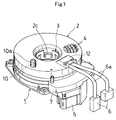
Claim 5 further defines the rotary connector according toClaim 2 orClaim 4, wherein the projection has an inclined surface on a side remote from the terminal strap. The construction allows the cut end of the flat cable to move to the center of the rotary connector while rotating, after the flat cable has been cut off. Thus, the construction prevents the cat end of the flat cable from entering the gap between the guide and the inner wall of the side housing. Attached drawings illustrate an embodiment of the present invention, in which: - Fig. 1 is a partially cross-sectional perspective view of an embodiment of the invention;
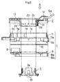
- Fig. 2 is a cross-sectional view of the embodiment of the invention taken along the diameter;
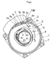
- Fig. 3 is an enlarged perspective view of a stator housing having a flat cable according to the embodiment of the invention;
- Fig. 4 is a top plan view of the stator housing having the flat cable according to the embodiment of the invention and.
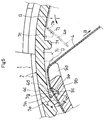
- Fig. 5 is an enlarged view of a part depicted at H of Fig. 4.
-
- Referring to the drawings,
reference numerals Reference numerals - A rotary connector includes the
stator housing 1,rotor housing 2 rotatably assembled to thestator housing 1, and theflat cable 4 in the shape of a spiral. Theflat cable 4 is housed in a space G defined by thestator housing 1 and therotor housing 2. - The
stator housing 1 is a stationary component that is screwed down on the combination switch (not shown) of, for example, an automobile. Thestator housing 1 includes aside housing 7 and abottom housing 8 combined with theside housing 7. For more detail, theside housing 7 has afitting hole 7a and the bottom housing has afitting projection 8a. Thefitting projection 8a is fitted into thefitting hole 7a, thereby assembling thebottom housing 8 to theside housing 7. Theside housing 7 andbottom housing 8 may be formed in one piece, thereby providing a singlepiece stator housing 1. - The side housing 7 and the
bottom housing 8 havebase portions 7b and 8b, respectively, that are flush with each other when they are assembled together. Thus, when thestator housing 1 has been fixed to the combination switch, both thebase portions 7b and 8b abut the combination switch. Therefore, if an external force is exerted on thebottom housing 8 in a direction shown by arrow A of Fig. 2, the base portion 8b abuts the combination switch, so that thebottom housing 8 is prevented from being deformed in the direction shown by the arrow A as well as thefitting projection 8a of thebottom housing 8 is prevented from dropping out of thefitting hole 7a of theside housing 7. - As shown in Fig. 2, the
bottom housing 8 has aguide 9 that holds an end of theflat cable 4 and guides theflat cable 4 in a space G defined by thestator housing 1 and therotor housing 2. There is provided aslide sheet 15 on top of thebottom housing 8. - The
rotor housing 2 is rotatably fitted into thestator housing 1 and is coupled to the steering wheel (not shown) by means of acoupling pin 10 having aresilient cover 10a fitted thereover. Therotor housing 2 hasprojections 2b and astepped portion 2c on its inner circumferential surface 2a. Theprojections 2b fit intofitting portions 3a formed on anattachment 3. The steppedportions 2cabut projecting straps 3b formed on theattachment 3. - The
rotor housing 2 has acord cover 12 that coverscords 6a ofconnectors 6 led out of therotor housing 2 and secures a later-described supportingmember 11 to therotor housing 2. Thecord cover 12 is inserted into the top surface of therotor housing 2 and is fixed by heat bonding or ultrasonic bonding. Therotor housing 2 has acaution label 13 stuck on the top surface of therotor housing 2 as shown in Fig. 2. Thecaution label 13 lists cautions about the handling of the rotary connector. - The supporting
member 11 is a component that supports one end of theflat cable 4 as shown in Fig. 2. The supportingmember 11 is also a member that prevents theflat cable 4 from buckling, thereby protecting theflat cable 4 from breakage and damage. - The
attachment 3 is a member that couples thestator housing 1 to therotor housing 2. Theattachment 3 has thefitting portions 3a and projectingstraps 3b. Thefitting portions 3a resiliently engage theprojections 2b of therotor housing 2, and the projectingstraps 3b abut the steppedportions 2c of therotor housing 2. Theattachment 3 slides on the inner surface of thebottom housing 8, serving as a radial (direction of radius) bearing. - As shown in Fig. 4, the
flat cable 4 includes a plurality ofconductive wires 4a and sheets of resin film 4b between which the plurality ofconductive wires 4a are sandwiched. The plurality of conductive belt-shapedwires 4a are arranged at predetermined intervals and are sandwiched between two sheets of insulating resin film 4b. Theflat cable 4 has one end fixed to aterminal strap 14 that is electrically connected to aconnector 5 and the other end fixed to the supportingmember 11 mounted to therotor housing 2. - The
conductive wires 4a have front and back surfaces bonded to two sheets of resin film 4b. Theconductive wires 4a are flat belt-shaped and have one ends thereof connected to the air bag apparatus accommodated in the steering wheel and the other ends thereof electrically connected to a power supply and sensors of the air bag apparatus. Theconductive wires 4a include a total of three wires; two wires for the air bag and one wire for a horn. The number of conductive wires is not limited to three and may be selected in accordance with the design purpose. - The resin film 4b is of the construction in which two laminated films of, for example, polyethylene terephthalate are contact bonded by heat or bonded by an adhesive such that the plurality of
conductive wires 4a are insulated from each other. - The
flat cable 4 is housed in a doughnut-shaped space G defined by thestator housing 1 and therotor housing 2. Theflat cable 4 is rotatable leftward and rightward, at least two complete rotations in each direction. One end of theflat cable 4 is electrically connected to theconnector 5 of thestator housing 1 via theterminal strap 14, and the other end of theflat cable 4 is connected to theconnectors 6 of therotor housing 2 via the supportingmember 11. - As shown in Figs. 2 and 4, the supporting
member 11 connected to theflat cable 4 is fastened to the outer wall of ahollow shaft 2d of therotor housing 2. As shown in Figs. 3 and 4, theterminal strap 14 located at the other end of theflat cable 4 is disposed between aninner wall 7c of theside housing 7 and theguide 9 near the upper outer periphery of thebottom housing 8. - The
terminal strap 14 is an resin material in which conductors (not shown) are insert molded. The conductors have lateral ends connected to the respectiveconductive wires 4a and downward ends connected to the respective ends of the terminals (not shown) of theconnector 5. Theterminal strap 14 is mounted to the bottom surface of thebottom housing 8. As shown in Figs. 3 and 4, theterminal strap 14 engages abottom surface 9a of a recess formed in theguide 9 and is received betweenprojections inner wall 7c of theside housing 7. - The
projections inner wall 7c of theside housing 7. As shown in Figs. 3 and 4, theprojection 7d cooperates with thebottom surface 9a of theguide 9 to support theterminal strap 14 therebetween. - As shown in Figs. 3, 4, and 5, a
projection 7e opposes aguide strap 9b of theguide 9 and is aligned with an edge of arecess 9c formed in a surface of theguide strap 9b facing theinner wall 7c. Theprojection 7e cooperates with theguide strap 9b to support the end of theflat cable 4, and cooperates with therecess 9c to prevent the cut end of theflat cable 4 from again entering a gap between theguide 9 and theinner wall 7c after theflat cable 4 has been cut off at the connection C connected to theterminal strap 14. In this manner, the construction prevents the cut end of theflat cable 4 from short-circuiting. - The
projection 7e has a side surface 7g closer to the small-width strap 9d. The side surface 7g is inclined to make an acute angle with theflat cable 4. As shown in Fig. 5, when a flat cable 4c that has been cut off enters a space between theinner wall 7c and theguide strap 9b, the cut end of the flat cable 4c strikes the side surface 7g and slips to abase portion 7h of theprojection 7e where the tip of the flat cable 4c is finally stopped. In this manner, the flat cable 4c is prevented from entering the gap between theguide 9 and theinner wall 7c. - As shown in Fig. 5, the
projection 7f prevents aflat cable 4e from again entering the gap between theguide 9 andinner wall 7c after theflat cable 4 has been cut off, ensuring that theflat cable 4e will not be short-circuited to inadvertently fire the air bag. Theprojection 7f should be provided at a location near the small-width strap 9d, including alocation 7i shown by a phantom line adjacent to the small-width strap 9d and a location 7j further away from the small-width strap 9d as shown in Fig. 5. - The
projections surface 7k formed on the projection 7j shown by phantom lines in Fig. 5. Thesurface 7k guides theflat cable 4e, which moves toward theguide 9 in a direction shown by arrow I, toward the center of the rotary connector. Theside surface 7k is formed on a side of theprojections guide 9. Theside surface 7k may be a flat surface or a curved surface. - The
guide 9 is a projected strap provided at a location over theconnector 5 of thebottom housing 8. Theguide 9 includesguide strap 9b,recess 9c, small-width strap 9d, and the recess having thebottom surface 9a. Theguide 9 extends along theinner wall 7c of theside housing 7, generally describing an arc. - The
bottom surface 9a of the recess is a bottom surface of a groove with which theprojection 7d and theterminal strap 14 are engaged. When the user rotates the steering wheel, theguide strap 9b guides theflat cable 4 in such a way that theflat cable 4 connected to theterminal strap 14 expands or contracts within theside housing 7 while maintaining its spiral shape. - Just like the
projections flat cable 4 has been cut off at the connection C connected to theterminal strap 14, therecess 9c serves to prevent the reentering of theflat cable 4 between theinner wall 7c and theguide 9 which would otherwise cause a short-circuit. Therecess 9c is a substantially U-shaped groove having aside wall 9e. Theside wall 9e is closer to theterminal strap 14 and is aligned with the tip of the side surface 7g of theprojection 7e. - The
side wall 9e is inclined such that theside wall 9e makes an acute angle with theflat cable 4. When a flat cable 4d again enters the gap between theinner wall 7c and theguide strap 9b as shown in Fig. 5 after theflat cable 4 has been cut, the tip of the flat cable 4d strikes theside wall 9e and slides on theside wall 9e toward arecess 9c. The tip of the cable 4d is stopped at therecess 9c. Thus, the flat cable 4d is prevented from entering the gap between theguide 9 and theinner wall 7c. - The small-
width strap 9d is a projecting strap formed at the lower end of theguide strap 9b and is in contact with theflat cable 4. The small-width strap 9d has a shorter vertical width than theguide strap 9b. When the user operates the steering wheel to which the rotary connector is incorrectly assembled, the small-width strap 9d exerts a concentrated stress on theflat cable 4 that is in contact with the small-width strap 9d, thereby cutting off theflat cable 4 at the connection C connected to theterminal strap 14. The small-width strap 9d has a rounded tip portion such that the friction resistance between theflat cable 4 and the small-width strap 9d is small when the rotary connector is assembled correctly. The small-width strap 9d may be at a vertically upper end or middle of theguide strap 9b, provided that the small-width strap 9d is at the tip of theguide strap 9b. The small-width strap 9d should be located where the small-width strap 9d presses theconductive wires 4a hard, so that theflat cable 4 can be cut off efficiently at the connection C connected to theterminal strap 14. - The rotary connector having the
flat cable 4 operates as follows:
The rotary connector has theconnectors 6 connected to, for example, an air bag apparatus (not shown) on the steering wheel side and theother connector 5 to, for example, air bag controller (not shown) on the vehicle side. Thus, in the event of crash of the vehicle, the electrical signal generated by the air bag controller is sent to the air bag apparatus provided at the steering pad via thefiat cable 4 of the rotary connector, thereby firing the inflater to inflate the air bag. - When the user operates the steering wheel, the steering wheel rotates together with the
rotor housing 2 andattachment 3, so that theflat cable 4 slides. When the rotary connector is correctly mounted to the steering wheel, the steering wheel andflat cable 4 rotate leftward and rightward from the position at which the vehicle runs straightly, rotating through two complete rotations in each direction. No load is exerted on the contact portion D between theflat cable 4 and the small-width strap 9d of theguide 9. Additionally, theflat cable 4 is not damaged because the small-width strap 9d has a curved surface. - For example, Fig. 4 illustrates the rotary connector when the user operates the steering wheel rightward in the direction shown by arrow E more than one rotation, if the rotary connector has been inadvertently assembled with the steering wheel rotated rightward by one complete rotation from the neutral position. Rotating the steering wheel causes the
flat cable 4 to be taut. Theflat cable 4 near theguide 9 is pulled in the direction shown by arrow B as shown in Figs. 3 and 4, so that a stress is concentrated on the contact portion D at which theflat cable 4 is in contact with the small-width strap 9d. The small-width strap 9d has a shorter vertical dimension than theguide 9, so that the stress exerted on theflat cable 4 at the contact portion D is large. - When the user operates the steering wheel further in the direction shown by arrow E, for example, to make a right turn, the
flat cable 4 is cut off at the weakest portion, i.e., the connection portion C connected to theterminal strap 14. Since theflat cable 4 is cut off, the steering wheel can be operated in the same manner that the rotary connector is assembled correctly. - When the steering wheel has been rotated more than one complete rotation rightward in the direction shown by arrow E after the
flat cable 4 has been cut off, the cut end of the connection portion C is pulled in the direction shown by arrow B, passing between theguide 9 and theinner wall 7c to the space G in theside housing 7. - When the user rotates the steering wheel in a direction shown by arrow F shown in Fig. 4, the cut end of the connection portion C of the
flat cable 4 also moves in the direction shown by arrow F. The cut end of the connection portion C of theflat cable 4 strikes theprojection 7f, which prevents theflat cable 4 from entering the gap between theguide 9 and theinner wall 7c. - Thus, even if the cut end of the connection portion C passes between the small-
width strap 9d and theinner wall 7c into the space between theside wall 9e and theinner wall 7c, theprojection 7e cooperates with therecess 9c to prevent the cut end of the connection portion C from entering further through the gap to a position where the cut end of the connection portion C may reach theterminal strap 14. - Thus, the construction prevents the short-circuit of the
conductive wires 4a of theflat cable 4 to the terminals of theterminal strap 14, which would otherwise cause the air bag system to go off spontaneously. -
- 1: stator housing,
- 2: rotor housing
- 4. 4c, 4d, 4e: flat cables
- 7c: inner wall
- 7e, 7f, 7i, 7j: projections
- 7g, 7k: side surfaces
- 9: guide
- 9c: recess
- 9d: small-width strap
- 11: supporting member
- 14: terminal strap
- G: space
-
Claims (5)
- A rotary connector having a flat cable (4) with one end connected to a terminal strap (14) and the other end connected to a supporting member (11), the flat cable (4) being in the shape of a spiral and being accommodated in a space (G) defined by a stator housing (1) and a rotor housing (2) rotatably assembled to the stator housing (1), characterized in that:the terminal strap (14) is located between an inner wall (7c) of the stator housing (1) and a guide (9) disposed near the inner wall (7c);the guide (9) has a small-width strap (9d) with a curved surface in contact with the flat cable (4); andthe flat cable (4) is routed to pass through a gap between the inner wall (7c) of the stator housing (1) and a small-width strap (9d) into the space (G) in the stator housing.
- The rotary connector according to Claim 1, wherein the stator housing (1) has a projection (7f, 7i, 7j) formed on the inner wall (7c) near the small-width strap (9d).
- The rotary connector according to Claim 1 or Claim 2, wherein the stator housing (1) has a projection (7e) formed on the inner wall (7c) between the terminal strap (14) and the small-width strap (9d).
- The rotary connector according to Claim 3, wherein the guide (9) has a recess (9c) near a location facing the projection (7e).
- The rotary connector according to Claim 2 or Claim 4, wherein the projection (7e, 7j) has an inclined surface on a side thereof remote from the terminal strap (14).
Applications Claiming Priority (2)
| Application Number | Priority Date | Filing Date | Title |
|---|---|---|---|
| JP20114499 | 1999-07-15 | ||
| JP20114499A JP3693859B2 (en) | 1999-07-15 | 1999-07-15 | Rotating connector device |
Publications (2)
| Publication Number | Publication Date |
|---|---|
| EP1069657A1 true EP1069657A1 (en) | 2001-01-17 |
| EP1069657B1 EP1069657B1 (en) | 2004-11-03 |
Family
ID=16436137
Family Applications (1)
| Application Number | Title | Priority Date | Filing Date |
|---|---|---|---|
| EP00114896A Expired - Lifetime EP1069657B1 (en) | 1999-07-15 | 2000-07-12 | Rotary connector |
Country Status (6)
| Country | Link |
|---|---|
| US (1) | US6343946B1 (en) |
| EP (1) | EP1069657B1 (en) |
| JP (1) | JP3693859B2 (en) |
| KR (1) | KR100646542B1 (en) |
| DE (1) | DE60015444T2 (en) |
| TW (1) | TW508607B (en) |
Cited By (2)
| Publication number | Priority date | Publication date | Assignee | Title |
|---|---|---|---|---|
| US7038139B2 (en) * | 2002-04-26 | 2006-05-02 | Toyoda Koki Kabushiki Kaisha | Spiral cable device |
| CN103515820A (en) * | 2012-06-21 | 2014-01-15 | 耐力株式会社 | Rotary connector device |
Families Citing this family (13)
| Publication number | Priority date | Publication date | Assignee | Title |
|---|---|---|---|---|
| JP2004031188A (en) * | 2002-06-27 | 2004-01-29 | Sumitomo Wiring Syst Ltd | Cable reel |
| US6854977B2 (en) * | 2002-09-13 | 2005-02-15 | Trw Inc. | Steering wheel rotary connector |
| US7104821B2 (en) * | 2004-09-16 | 2006-09-12 | Alps Electric Co., Ltd. | Rotary connector |
| JP4152414B2 (en) | 2006-02-09 | 2008-09-17 | 矢崎総業株式会社 | Rotating connector device |
| DE102006013434A1 (en) * | 2006-03-14 | 2007-09-20 | Valeo Schalter Und Sensoren Gmbh | Connecting device for transmitting electric power, in particular for a steering wheel heating of a vehicle |
| JP4891701B2 (en) * | 2006-08-23 | 2012-03-07 | ナイルス株式会社 | Rotating connector device |
| JP4797002B2 (en) * | 2007-08-10 | 2011-10-19 | ナイルス株式会社 | Cord member locking structure |
| JP5871437B2 (en) * | 2013-12-03 | 2016-03-01 | 古河電気工業株式会社 | Rotating connector |
| CN104518388B (en) * | 2015-01-06 | 2017-08-29 | 江苏飞锦达科技有限公司 | A kind of connection transfer device being used between rotary part and static component |
| CN104875985B (en) * | 2015-04-13 | 2017-08-25 | 江苏飞锦达科技有限公司 | A kind of Equipotential connection device and floating roof tank |
| KR102520052B1 (en) * | 2018-10-17 | 2023-04-11 | 후루카와 덴키 고교 가부시키가이샤 | swivel connector device |
| JP7303985B2 (en) * | 2019-12-02 | 2023-07-06 | 株式会社オートネットワーク技術研究所 | connector |
| KR102882374B1 (en) * | 2020-03-25 | 2025-11-07 | 후루카와 덴키 고교 가부시키가이샤 | Rotating connector device |
Citations (5)
| Publication number | Priority date | Publication date | Assignee | Title |
|---|---|---|---|---|
| US4824396A (en) * | 1987-05-27 | 1989-04-25 | Alps Electric Co., Ltd. | Electrical connection apparatus |
| US4936782A (en) * | 1988-05-23 | 1990-06-26 | Alps Electric Co., Ltd. | Flat cable for steering device of vehicle |
| EP0758596A2 (en) * | 1995-08-11 | 1997-02-19 | Yazaki Corporation | Electrical connecting device for connecting rotor with stator through cable |
| US5657940A (en) * | 1995-01-12 | 1997-08-19 | Yazaki Corporation | Relay device for rotating members |
| US5772456A (en) * | 1995-03-28 | 1998-06-30 | Niles Parts Co., Ltd. | Housing structure for rotary connectors |
Family Cites Families (6)
| Publication number | Priority date | Publication date | Assignee | Title |
|---|---|---|---|---|
| DE3728387A1 (en) | 1987-08-26 | 1989-03-09 | Voith Gmbh J M | EXPANDING BODY |
| JP2575481Y2 (en) * | 1991-08-21 | 1998-06-25 | 古河電気工業株式会社 | Fixing structure of flat cable connection part in rotary connector |
| JP3373966B2 (en) * | 1995-02-10 | 2003-02-04 | アルプス電気株式会社 | Rotating connector |
| US5674082A (en) * | 1995-02-21 | 1997-10-07 | Niles Parts Co., Ltd. | Rotary connector device |
| US5645441A (en) * | 1995-05-18 | 1997-07-08 | Niles Parts Co., Ltd. | Rotary connector device |
| DE19702538B4 (en) * | 1996-01-25 | 2004-12-02 | Alps Electric Co., Ltd. | rotary connector |
-
1999
- 1999-07-15 JP JP20114499A patent/JP3693859B2/en not_active Expired - Fee Related
-
2000
- 2000-06-12 TW TW089111443A patent/TW508607B/en not_active IP Right Cessation
- 2000-07-12 EP EP00114896A patent/EP1069657B1/en not_active Expired - Lifetime
- 2000-07-12 DE DE60015444T patent/DE60015444T2/en not_active Expired - Lifetime
- 2000-07-13 US US09/616,368 patent/US6343946B1/en not_active Expired - Lifetime
- 2000-07-14 KR KR1020000040477A patent/KR100646542B1/en not_active Expired - Fee Related
Patent Citations (5)
| Publication number | Priority date | Publication date | Assignee | Title |
|---|---|---|---|---|
| US4824396A (en) * | 1987-05-27 | 1989-04-25 | Alps Electric Co., Ltd. | Electrical connection apparatus |
| US4936782A (en) * | 1988-05-23 | 1990-06-26 | Alps Electric Co., Ltd. | Flat cable for steering device of vehicle |
| US5657940A (en) * | 1995-01-12 | 1997-08-19 | Yazaki Corporation | Relay device for rotating members |
| US5772456A (en) * | 1995-03-28 | 1998-06-30 | Niles Parts Co., Ltd. | Housing structure for rotary connectors |
| EP0758596A2 (en) * | 1995-08-11 | 1997-02-19 | Yazaki Corporation | Electrical connecting device for connecting rotor with stator through cable |
Cited By (3)
| Publication number | Priority date | Publication date | Assignee | Title |
|---|---|---|---|---|
| US7038139B2 (en) * | 2002-04-26 | 2006-05-02 | Toyoda Koki Kabushiki Kaisha | Spiral cable device |
| CN103515820A (en) * | 2012-06-21 | 2014-01-15 | 耐力株式会社 | Rotary connector device |
| CN103515820B (en) * | 2012-06-21 | 2017-04-26 | 法雷奥日本株式会社 | Rotary connector device |
Also Published As
| Publication number | Publication date |
|---|---|
| JP3693859B2 (en) | 2005-09-14 |
| TW508607B (en) | 2002-11-01 |
| KR100646542B1 (en) | 2006-11-17 |
| US6343946B1 (en) | 2002-02-05 |
| JP2001028286A (en) | 2001-01-30 |
| EP1069657B1 (en) | 2004-11-03 |
| DE60015444T2 (en) | 2005-10-13 |
| KR20010015334A (en) | 2001-02-26 |
| DE60015444D1 (en) | 2004-12-09 |
Similar Documents
| Publication | Publication Date | Title |
|---|---|---|
| EP1069657B1 (en) | Rotary connector | |
| CA2142051C (en) | Two-piece clockspring with lock and wire harness assembly | |
| JP4155731B2 (en) | Fixture for wire harness | |
| US9882329B2 (en) | Rotating contactor for a motor vehicle steering column | |
| US6854977B2 (en) | Steering wheel rotary connector | |
| JP3416413B2 (en) | Rotating connector | |
| JP5802156B2 (en) | Rotating connector | |
| JP3305154B2 (en) | Housing structure in rotary connector device | |
| US5980285A (en) | Rotary connector apparatus | |
| EP1117161B1 (en) | Rotary connector | |
| EP1052743B1 (en) | Vehicle-mounted rotary connector | |
| US6770991B2 (en) | Roll connector structure for a vehicle | |
| JP5395687B2 (en) | Rotating connector | |
| US7097478B2 (en) | Electric connecting device | |
| JP3238843B2 (en) | Housing interference prevention structure in rotary connector device | |
| JP3238844B2 (en) | Mounting structure of sliding sheet in rotary connector device | |
| JP3595362B2 (en) | Housing structure in rotary connector device | |
| JP3345276B2 (en) | Housing structure in rotary connector device | |
| CN1319222C (en) | Rotary connector | |
| JP5872933B2 (en) | Rotating connector | |
| JPH08227779A (en) | Stator housing structure in rotary connector device | |
| JPH08227776A (en) | Cord fixing structure in rotary connector device | |
| JPH08227782A (en) | Grease basin structure in rotary connector device | |
| JP2000195639A (en) | Rotary connector device | |
| JPH07296927A (en) | Rotary connector device |
Legal Events
| Date | Code | Title | Description |
|---|---|---|---|
| PUAI | Public reference made under article 153(3) epc to a published international application that has entered the european phase |
Free format text: ORIGINAL CODE: 0009012 |
|
| AK | Designated contracting states |
Kind code of ref document: A1 Designated state(s): DE FR GB |
|
| AX | Request for extension of the european patent |
Free format text: AL;LT;LV;MK;RO;SI |
|
| 17P | Request for examination filed |
Effective date: 20010130 |
|
| AKX | Designation fees paid |
Free format text: DE FR GB |
|
| GRAP | Despatch of communication of intention to grant a patent |
Free format text: ORIGINAL CODE: EPIDOSNIGR1 |
|
| GRAA | (expected) grant |
Free format text: ORIGINAL CODE: 0009210 |
|
| GRAS | Grant fee paid |
Free format text: ORIGINAL CODE: EPIDOSNIGR3 |
|
| AK | Designated contracting states |
Kind code of ref document: B1 Designated state(s): DE FR GB |
|
| REG | Reference to a national code |
Ref country code: GB Ref legal event code: FG4D |
|
| REF | Corresponds to: |
Ref document number: 60015444 Country of ref document: DE Date of ref document: 20041209 Kind code of ref document: P |
|
| PLBE | No opposition filed within time limit |
Free format text: ORIGINAL CODE: 0009261 |
|
| STAA | Information on the status of an ep patent application or granted ep patent |
Free format text: STATUS: NO OPPOSITION FILED WITHIN TIME LIMIT |
|
| ET | Fr: translation filed | ||
| 26N | No opposition filed |
Effective date: 20050804 |
|
| REG | Reference to a national code |
Ref country code: DE Ref legal event code: R082 Ref document number: 60015444 Country of ref document: DE Representative=s name: MAI, OPPERMANN & PARTNER I. L., DE Ref country code: DE Ref legal event code: R082 Ref document number: 60015444 Country of ref document: DE Representative=s name: OANDO OPPERMANN & OPPERMANN LLP, DE |
|
| PGFP | Annual fee paid to national office [announced via postgrant information from national office to epo] |
Ref country code: DE Payment date: 20140709 Year of fee payment: 15 |
|
| PGFP | Annual fee paid to national office [announced via postgrant information from national office to epo] |
Ref country code: GB Payment date: 20140709 Year of fee payment: 15 Ref country code: FR Payment date: 20140708 Year of fee payment: 15 |
|
| REG | Reference to a national code |
Ref country code: DE Ref legal event code: R082 Ref document number: 60015444 Country of ref document: DE Representative=s name: MAI, OPPERMANN & PARTNER I. L., DE Ref country code: DE Ref legal event code: R082 Ref document number: 60015444 Country of ref document: DE Representative=s name: OANDO OPPERMANN & OPPERMANN LLP, DE |
|
| REG | Reference to a national code |
Ref country code: DE Ref legal event code: R082 Ref document number: 60015444 Country of ref document: DE Representative=s name: OANDO OPPERMANN & OPPERMANN LLP, DE |
|
| REG | Reference to a national code |
Ref country code: DE Ref legal event code: R119 Ref document number: 60015444 Country of ref document: DE |
|
| GBPC | Gb: european patent ceased through non-payment of renewal fee |
Effective date: 20150712 |
|
| PG25 | Lapsed in a contracting state [announced via postgrant information from national office to epo] |
Ref country code: DE Free format text: LAPSE BECAUSE OF NON-PAYMENT OF DUE FEES Effective date: 20160202 Ref country code: GB Free format text: LAPSE BECAUSE OF NON-PAYMENT OF DUE FEES Effective date: 20150712 |
|
| REG | Reference to a national code |
Ref country code: FR Ref legal event code: ST Effective date: 20160331 |
|
| PG25 | Lapsed in a contracting state [announced via postgrant information from national office to epo] |
Ref country code: FR Free format text: LAPSE BECAUSE OF NON-PAYMENT OF DUE FEES Effective date: 20150731 |