EP0758596A2 - Electrical connecting device for connecting rotor with stator through cable - Google Patents
Electrical connecting device for connecting rotor with stator through cable Download PDFInfo
- Publication number
- EP0758596A2 EP0758596A2 EP96111603A EP96111603A EP0758596A2 EP 0758596 A2 EP0758596 A2 EP 0758596A2 EP 96111603 A EP96111603 A EP 96111603A EP 96111603 A EP96111603 A EP 96111603A EP 0758596 A2 EP0758596 A2 EP 0758596A2
- Authority
- EP
- European Patent Office
- Prior art keywords
- rotor
- flat cable
- stator
- carrier
- movable member
- Prior art date
- Legal status (The legal status is an assumption and is not a legal conclusion. Google has not performed a legal analysis and makes no representation as to the accuracy of the status listed.)
- Withdrawn
Links
Images


Classifications
-
- B—PERFORMING OPERATIONS; TRANSPORTING
- B60—VEHICLES IN GENERAL
- B60R—VEHICLES, VEHICLE FITTINGS, OR VEHICLE PARTS, NOT OTHERWISE PROVIDED FOR
- B60R16/00—Electric or fluid circuits specially adapted for vehicles and not otherwise provided for; Arrangement of elements of electric or fluid circuits specially adapted for vehicles and not otherwise provided for
- B60R16/02—Electric or fluid circuits specially adapted for vehicles and not otherwise provided for; Arrangement of elements of electric or fluid circuits specially adapted for vehicles and not otherwise provided for electric constitutive elements
- B60R16/023—Electric or fluid circuits specially adapted for vehicles and not otherwise provided for; Arrangement of elements of electric or fluid circuits specially adapted for vehicles and not otherwise provided for electric constitutive elements for transmission of signals between vehicle parts or subsystems
- B60R16/027—Electric or fluid circuits specially adapted for vehicles and not otherwise provided for; Arrangement of elements of electric or fluid circuits specially adapted for vehicles and not otherwise provided for electric constitutive elements for transmission of signals between vehicle parts or subsystems between relatively movable parts of the vehicle, e.g. between steering wheel and column
Definitions
- the present invention relates to an electrical connecting device between a stator and a rotor rotatably arranged in the stator, which connects electrical elements on the stator's side of a steering apparatus of a vehicle with other electrical elements on the rotor's side through the intermediary of a flat cable arranged in an annular space defined between the stator and the rotor.
- an electrical connecting device which includes a rotor assembly consisting of a first rotor and a second rotor, into which a handle spindle of the vehicle is inserted and secured to the rotor assembly, and a stator consisting of an upper cover and an under cover.
- Both upper cover and under cover form a cylindrical housing in which the rotor assembly is accommodated so as to rotate and which is fixed to a member on the steering column's side of the vehicle.
- the FFC serves to connect electrical elements on the handle's side of the vehicle with other elements on the steering column's side.
- a carrier Fixed to the housing consisting of the upper cover and under cover is an internal gear in which the FFC is accommodated.
- a carrier mounted on both of a lower flange of the internal gear and a lower flange of the first rotor is a carrier as "a moving member" which is capable of rotating with respect to the internal gear and the first rotor relatively.
- the carrier is provided with one and only gap in the circumferential direction, providing C-shaped configuration.
- the FFC is wound along an annular space defined between the outer peripheral face of the first rotor and the inner peripheral face of the carrier and then looped around a circumferential end of the carrier, forming a turning part of the FFC.
- the remaining FFC is wound along another annular space defined between the inner peripheral face of the internal gear and the outer peripheral face of the carrier in the opposite direction to the winding direction about the first rotor.
- the FFC is drawn out of the internal gear through a notch formed in the internal gear.
- a top face of the carrier is brought into "surface” contact with the cover, while an under face of the carrier is brought into surface contact with the lower flanges of the first rotor and the internal gear. Further, the inner and outer peripheral faces of the carrier are brought into surface contact with the flat cable in the longitudinal direction.
- the inner and outer peripheral faces of the carrier are brought into "line” contact with the flat cable since the carrier has a projection formed on the outer peripheral face.
- the carrier is formed to have a large mass occupying the most part of the annular space.
- an electrical connecting device comprising:
- the stator comprises an upper cover and an under cover to be fitted to the upper cover.
- stator further comprises an internal gear fixed to the under cover, while the rotor has a gear portion formed on an outer periphery thereof.
- the movable member comprises a carrier and a plurality planetary gears rotatably carried by the carrier and that the planetary gears are arranged so as to mesh with the internal gear and the gear portion of the rotor.
- the internal gear is provided with a notch through which the flat cable is drawn out of the internal gear.
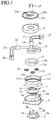
- Fig. 1 is a perspective view showing a disassembled electrical connecting device in accordance with an embodiment of the present invention.
- Fig. 2 is a plan view of the electrical connecting device of the embodiment, showing a flexible flat cable in the accommodated condition;
- Fig. 3 is a perspective view of a carrier which is used in the electrical connecting device of Fig. 1.
- FIG. 1 is a perspective view of an electrical connecting device in an exploded condition.
- the electrical connecting device includes a first rotor 1 and a second rotor 2 as "rotor" of the invention, into which a not-shown handle spindle of the vehicle is inserted and secured, and an upper cover 3 and an under cover 5 as “stator” of the invention, which constitute a cylindrical housing.
- the rotor In the housing, the rotor is carried so as to rotate therein.
- the housing is fixed to a not-shown member on the steering column's side of the vehicle.
- a flexible flat cable (FFC) 9 Accommodated in an annular space 7 defined between the rotor and the housing is a flexible flat cable (FFC) 9 which connects electrical elements (not shown) on the handle's side to other electrical elements on the steering column's side.
- FFC flexible flat cable
- an internal gear 11 Fixed in the housing consisting of the upper cover 3 and the under cover 5 is an internal gear 11 in which the FFC 9 is accommodated.
- a carrier 13 constituting "moving member" of the invention is arranged so as to rotate with respect to the first rotor 1 and the internal gear 11 relatively.
- the internal gear 11 is provided on a lower internal face thereof with a gear portion 11b, while the first rotor 1 is provided on a lower external face thereof with a gear portion 1b to be opposed to the gear portion 1b.
- the respective gears portions 11b, 1b are in mesh with a plurality of planetary gears 15 rotatably mounted on an under face of the carrier 13.
- the carrier 13 rotates and moves to the same direction as the first rotor's direction at the fixed deceleration ratio with respect to the first rotor 1 with revolutions of the planetary gears 15.
- the carrier 13 is provided in the circumferential direction with one and only opening (gap) 13a, providing C-shaped configuration.
- Figure 2 shows the FFC 9 in its accommodated condition in the annular space by a double-dotted line.
- the FFC 9 has a lapel part 9a adjacent to one end on the inner peripheral side, which is fixed to a fixing part 1c of the first rotor 1 and connected to a connector 17 through the intermediary of a molding part 19 and lead wires 21.
- the FFC 9 drawn out of the molding part 19 is wound along an annular space defined between the outer peripheral face of the first rotor 1 and the inner peripheral face of the carrier 13 and then looped around an end 13b of the carrier 13 to form a turning part 9b of the FFC 9.
- the FFC 9 is wound along an annular space defined between the inner peripheral face of the internal gear 11 and the outer peripheral face of the carrier 13 in the opposite direction and then drawn out of the internal gear 11 through a notch 11c, so that a molding part 22 attached to the other end of the FFC 9 is fixed in a swelling part 5a of the undercover 5.
- Connectors 24 are connected to the molding part 22 through lead wires 23.
- the under cover 5 is covered with an upper cover 25 which rotates together with the first and second rotors 1, 2.
- the molding part 19 of the FFC 9 is secured in a fixing part 25a formed on the upper cover 25.
- Three screw holes 25b are formed in the upper cover 25, while three boss parts 2a are formed on an upper face of the second rotor 2 for engagement with the holes 25b, respectively.
- Each boss part 2a is provided on an upper end thereof with a screw hole 2b.
- the boss parts 2a are inserted into insertion grooves 1d formed from the lower face of the first rotor 1 upwardly, so that respective leading ends of the parts 2a abut on an under face of an upper flange 1e of the first rotor 1.
- the upper flange 1e is provided with three screw holes 1f.
- the rotors and the housing can be assembled to each other by inserting three screws 27 into the screw holes 25 of the upper cover 25 and the screw holes 1f of the first rotor 1 and sequent screwing into the screw holes 2b of the second rotor 2, respectively.
- the FFC 9 has a length enough to follow several rotations of the handle with several rotations. Therefore, with the clockwise rotation of the first rotor 1 in Fig. 2, the FFC 9 (a part) wound about the outer periphery of the first rotor 1 can be undid, while such an undid part of the FFC 9 is gradually wound between the inner periphery of the internal gear 11 and the outer periphery of the carrier 13. On the contrary, when the first rotor 1 rotates in the counter-clockwise rotation in Fig. 2, the FFC 9 (a part) wound between the inner periphery of the internal gear 11 and the outer periphery of the carrier 13 is undid, while such an undid part of the FFC 9 is gradually wound about the first rotor 1. At this time, the turning part 9b of the FFC 9 moves in the circumferential direction of the housing together with the carrier 13.
- the carrier 13 has a pusher part 13e for pushing the FFC 9, which is arranged in the vicinity of an end 13c opposite to the end 13b defining the above gap 13a.
- the pusher part 13e is so formed as to project from an inner edge of the end 13c toward an inner edge of the end 13b, defining a through opening 13d for passing the FFC 9 therethrough.
- the inner peripheral face of the pusher part 13e is curved so as to form an identical surface together with the inner peripheral face of the carrier 13.
- the above-mentioned prevention of the FFC 9 from buckling can be carried out by a simple structure where the pusher part 13w is formed in integral with the carrier 13 of a C-shaped member, so that the increase in manufacturing cost can be minimized without an addition of any exclusive parts for preventing buckling and a deterioration in assembling workability.
- the pusher part 13e is constituted by an elastic member exhibiting an urging force directing the first rotor 1, it is possible to restrict an expansion of the FFC 9 wound about the outer periphery of the first rotor 1 toward the inner periphery of the carrier 13, so that the effect to prevent the FFC from buckling can be further improved.
Abstract
Description
- The present invention relates to an electrical connecting device between a stator and a rotor rotatably arranged in the stator, which connects electrical elements on the stator's side of a steering apparatus of a vehicle with other electrical elements on the rotor's side through the intermediary of a flat cable arranged in an annular space defined between the stator and the rotor.
- Recently, with the progress in electronic control technology for vehicles, a handle (or a steering wheel) in a steering apparatus of the vehicle has been provided with a variety of switches for electronic control and therefore, it has been required to connect such switches with electrical elements on the steering column's side of the vehicle by means of electrical wiring. Of course, since the handle of the vehicle is so constructed as to be rotatable in both clockwise and counter-clockwise directions at plural rotations, an electrical connection device having a flexible flat cable (FFC) has been used in order to connect a rotor shaft of the handle to a steering column electrically. In detail, the flexible flat cable is composed of a plurality of lead wires (or conductors) and arranged between the rotor secured to a handle spindle and a housing as the "stator" secured to the steering column, in a spiral manner or a "reversed" spiral manner where the flexible flat cable is turned back halfway. Note, the flexible flat cable will be also referred as "the FFC" for short, hereinafter.
- For instance, there is known an electrical connecting device which includes a rotor assembly consisting of a first rotor and a second rotor, into which a handle spindle of the vehicle is inserted and secured to the rotor assembly, and a stator consisting of an upper cover and an under cover. Both upper cover and under cover form a cylindrical housing in which the rotor assembly is accommodated so as to rotate and which is fixed to a member on the steering column's side of the vehicle. Being accommodated in an annular space defined between the rotor and the housing, the FFC serves to connect electrical elements on the handle's side of the vehicle with other elements on the steering column's side.
- Fixed to the housing consisting of the upper cover and under cover is an internal gear in which the FFC is accommodated. Mounted on both of a lower flange of the internal gear and a lower flange of the first rotor is a carrier as "a moving member" which is capable of rotating with respect to the internal gear and the first rotor relatively.
- The carrier is provided with one and only gap in the circumferential direction, providing C-shaped configuration. The FFC is wound along an annular space defined between the outer peripheral face of the first rotor and the inner peripheral face of the carrier and then looped around a circumferential end of the carrier, forming a turning part of the FFC. As a boundary of the turning part, the remaining FFC is wound along another annular space defined between the inner peripheral face of the internal gear and the outer peripheral face of the carrier in the opposite direction to the winding direction about the first rotor. Finally, the FFC is drawn out of the internal gear through a notch formed in the internal gear.
- By the way, it should be recognized that, in operation of the above-mentioned electrical connecting device, a top face of the carrier is brought into "surface" contact with the cover, while an under face of the carrier is brought into surface contact with the lower flanges of the first rotor and the internal gear. Further, the inner and outer peripheral faces of the carrier are brought into surface contact with the flat cable in the longitudinal direction. In connection, it is noted that in case of a carrier disclosed in Japanese Unexamined Patent Publication No. 4-333473, the inner and outer peripheral faces of the carrier are brought into "line" contact with the flat cable since the carrier has a projection formed on the outer peripheral face. In addition, the carrier is formed to have a large mass occupying the most part of the annular space.
- By the above-mentioned reasons, it will be understood that a frictional resistance of the carrier in moving is large.
- Hereat, when the first rotor is rotated so that the FFC is drawn from a space defined between the first rotor and the carrier into another space defined between the carrier and the internal gear, a part of the FFC wound about the periphery of the first rotor is inflated outwardly and urged against the inner peripheral face of the carrier. Therefore, also due to the above largesse in frictional resistance, it becomes difficult that the FFC moves to the outside of the carrier through the gap. Consequently, the FFC (part) wound about the first rotor is forced out of the gap of the carrier thereby causing the buckling of the FFC, so that it is impossible to pay out the FFC smoothly.
- In order to solve such a problem, Japanese Unexamined Patent Publication No. 4-328071 discloses a structure where a plurality of rollers, which are connected with each other through springs, are respectively arranged on the inner and outer peripheral faces of the carrier, so that the carrier is urged against the outer periphery of the first rotor and the inner periphery of the housing (internal gear).
- However, since the above structure requires many rollers and springs, the number of parts is increased to cause the workability in assembling for the worse and the manufacturing cost for the rise.
- It is therefore an object of the present invention to provide an electrical connecting device which is capable of preventing the flexible flat cable from buckling thereby to smooth the movement of the cable without increasing the number of parts.
- The object of the present invention described above can be accomplished by an electrical connecting device comprising:
- a stator in form of a substantially cylindrical housing;
- a rotor arranged in the stator so as to rotate therein;
- a flexible flat cable accommodated in an annular space defined between the rotor and the stator so that one end of the flat cable is fixed on the stator while the other end of the flat cable is fixed on the rotor thereby connecting elements on the rotor's side to other elements on the stator's side electrically, the flat cable being wound along the outer periphery of the rotor in one winding direction and wound along the inner periphery of the stator in the opposite winding direction through a turning part of the flat cable as a boundary; and
- a movable member arranged in the annular space so that spaces for accommodating the flat cable are defined between the movable member and the outer periphery of the rotor and between the movable member and the inner periphery of the stator, the movable member being constituted by a C-shaped member having a gap through which the turning part of the flat cable passes, whereby the movable member rotates relatively with respect to the rotation of the rotor while rotating and moving with respect to the stator with the circumferential movement of the turning part caused by winding the flat cable on the outer periphery of the rotor or winding the flat cable on the inner periphery of the stator;
- In this case, it is possible to restrict an expansion of the flexible flat cable wound about the outer periphery of the first rotor toward the inner periphery of the movable member, so that the effect to prevent the flexible flat cable from buckling can be further improved.
- More preferably, the stator comprises an upper cover and an under cover to be fitted to the upper cover.
- It is also preferable that the stator further comprises an internal gear fixed to the under cover, while the rotor has a gear portion formed on an outer periphery thereof.
- In addition, it is preferable that the movable member comprises a carrier and a plurality planetary gears rotatably carried by the carrier and that the planetary gears are arranged so as to mesh with the internal gear and the gear portion of the rotor.
- More preferably, the internal gear is provided with a notch through which the flat cable is drawn out of the internal gear.
- These and other objects and features of the present invention will become more fully apparent from the following description and appended claims taken in conjunction with the accompany drawing.
- Fig. 1 is a perspective view showing a disassembled electrical connecting device in accordance with an embodiment of the present invention.
- Fig. 2 is a plan view of the electrical connecting device of the embodiment, showing a flexible flat cable in the accommodated condition; and
- Fig. 3 is a perspective view of a carrier which is used in the electrical connecting device of Fig. 1.
- An embodiments of the present invention will be described with reference to the drawings. In figures, Fig. 1 is a perspective view of an electrical connecting device in an exploded condition.
- The electrical connecting device includes a
first rotor 1 and asecond rotor 2 as "rotor" of the invention, into which a not-shown handle spindle of the vehicle is inserted and secured, and anupper cover 3 and an undercover 5 as "stator" of the invention, which constitute a cylindrical housing. In the housing, the rotor is carried so as to rotate therein. The housing is fixed to a not-shown member on the steering column's side of the vehicle. Accommodated in an annular space 7 defined between the rotor and the housing is a flexible flat cable (FFC) 9 which connects electrical elements (not shown) on the handle's side to other electrical elements on the steering column's side. - Fixed in the housing consisting of the
upper cover 3 and the undercover 5 is aninternal gear 11 in which the FFC 9 is accommodated. On both of aflange 11a of theinternal gear 11 and a flange 1a of thefirst rotor 1, acarrier 13 constituting "moving member" of the invention is arranged so as to rotate with respect to thefirst rotor 1 and theinternal gear 11 relatively. Theinternal gear 11 is provided on a lower internal face thereof with agear portion 11b, while thefirst rotor 1 is provided on a lower external face thereof with agear portion 1b to be opposed to thegear portion 1b. Therespective gears portions planetary gears 15 rotatably mounted on an under face of thecarrier 13. That is, owing to rotations of theplanetary gears 15 with the rotation of thefirst rotor 1, thecarrier 13 rotates and moves to the same direction as the first rotor's direction at the fixed deceleration ratio with respect to thefirst rotor 1 with revolutions of theplanetary gears 15. - The
carrier 13 is provided in the circumferential direction with one and only opening (gap) 13a, providing C-shaped configuration. Figure 2 shows theFFC 9 in its accommodated condition in the annular space by a double-dotted line. TheFFC 9 has alapel part 9a adjacent to one end on the inner peripheral side, which is fixed to afixing part 1c of thefirst rotor 1 and connected to aconnector 17 through the intermediary of amolding part 19 andlead wires 21. TheFFC 9 drawn out of themolding part 19 is wound along an annular space defined between the outer peripheral face of thefirst rotor 1 and the inner peripheral face of thecarrier 13 and then looped around anend 13b of thecarrier 13 to form a turningpart 9b of theFFC 9. Next, the FFC 9 is wound along an annular space defined between the inner peripheral face of theinternal gear 11 and the outer peripheral face of thecarrier 13 in the opposite direction and then drawn out of theinternal gear 11 through anotch 11c, so that amolding part 22 attached to the other end of theFFC 9 is fixed in aswelling part 5a of the undercover 5.Connectors 24 are connected to themolding part 22 throughlead wires 23. - The under
cover 5 is covered with anupper cover 25 which rotates together with the first andsecond rotors molding part 19 of theFFC 9 is secured in a fixingpart 25a formed on theupper cover 25. Threescrew holes 25b are formed in theupper cover 25, while threeboss parts 2a are formed on an upper face of thesecond rotor 2 for engagement with theholes 25b, respectively. Eachboss part 2a is provided on an upper end thereof with ascrew hole 2b. Theboss parts 2a are inserted into insertion grooves 1d formed from the lower face of thefirst rotor 1 upwardly, so that respective leading ends of theparts 2a abut on an under face of an upper flange 1e of thefirst rotor 1. The upper flange 1e is provided with threescrew holes 1f. In assembly, the rotors and the housing can be assembled to each other by inserting threescrews 27 into the screw holes 25 of theupper cover 25 and the screw holes 1f of thefirst rotor 1 and sequent screwing into the screw holes 2b of thesecond rotor 2, respectively. - The
FFC 9 has a length enough to follow several rotations of the handle with several rotations. Therefore, with the clockwise rotation of thefirst rotor 1 in Fig. 2, the FFC 9 (a part) wound about the outer periphery of thefirst rotor 1 can be undid, while such an undid part of theFFC 9 is gradually wound between the inner periphery of theinternal gear 11 and the outer periphery of thecarrier 13. On the contrary, when thefirst rotor 1 rotates in the counter-clockwise rotation in Fig. 2, the FFC 9 (a part) wound between the inner periphery of theinternal gear 11 and the outer periphery of thecarrier 13 is undid, while such an undid part of theFFC 9 is gradually wound about thefirst rotor 1. At this time, the turningpart 9b of theFFC 9 moves in the circumferential direction of the housing together with thecarrier 13. - In the above-mentioned arrangement, according to the embodiment, the
carrier 13 has apusher part 13e for pushing theFFC 9, which is arranged in the vicinity of anend 13c opposite to theend 13b defining theabove gap 13a. In detail, thepusher part 13e is so formed as to project from an inner edge of theend 13c toward an inner edge of theend 13b, defining a throughopening 13d for passing theFFC 9 therethrough. - The inner peripheral face of the
pusher part 13e is curved so as to form an identical surface together with the inner peripheral face of thecarrier 13. - With the arrangement mentioned above, when the
first rotor 1 is rotated in the clockwise direction of Fig. 2 so that theFFC 9 is drawn out of a space defined between thefirst rotor 1 and thecarrier 13 into another space defined between theinternal gear 11 and thecarrier 13 through theopening 13d at thegap 13a and even though a part of theFFC 9 wound about thefirst rotor 1 is on the point of sticking out of thegap 13a since the part is swollen and urged against the inner peripheral face of thecarrier 13 frictionally, thepusher part 13e at thegap 13a serves to depress the swollen part of theFFC 9. Consequently, theFFC 9 can be moved smoothly without buckling. - That is, the above-mentioned prevention of the
FFC 9 from buckling can be carried out by a simple structure where the pusher part 13w is formed in integral with thecarrier 13 of a C-shaped member, so that the increase in manufacturing cost can be minimized without an addition of any exclusive parts for preventing buckling and a deterioration in assembling workability. - Furthermore, in case that the
pusher part 13e is constituted by an elastic member exhibiting an urging force directing thefirst rotor 1, it is possible to restrict an expansion of theFFC 9 wound about the outer periphery of thefirst rotor 1 toward the inner periphery of thecarrier 13, so that the effect to prevent the FFC from buckling can be further improved. - Finally, it will be understood by those skilled in the art that the foregoing description is one of preferred embodiments of the disclosed electrical connecting device, and that various changes and modifications may be made to the present invention without departing from the spirit and scope thereof.
whereby a through opening for passing through the flat cable is defined between the another circumferential end and the pusher part of the movable member. With the arrangement mentioned above, when the flexible flat cable is drawn out of a space defined between the first rotor and the movable member into another space defined between the stator and the movable member through the gap and even though a part of the flexible flat cable wound about the first rotor is on the point of sticking out of the gap since the part is swollen and urged against the inner peripheral face of the movable member frictionally, the pusher part at the gap serves to depress the swollen part of the flexible flat cable. Consequently, the flexible flat cable can be moved smoothly without buckling. In the present invention, preferably, the pusher part is constituted by an elastic member exhibiting an urging force directing the rotor.
Claims (6)
- An electrical connecting device comprising:a stator in form of a substantially cylindrical housing;a rotor arranged in said stator so as to rotate therein;a flexible flat cable accommodated in an annular space defined between said rotor and said stator so that one end of said flat cable is fixed on said stator while the other end of said flat cable is fixed on said rotor thereby connecting elements on said rotor's side to other elements on said stator's side electrically, said flat cable being wound along the outer periphery of said rotor in one winding direction and wound along the inner periphery of said stator in the opposite winding direction through a turning part of said flat cable as a boundary; anda movable member arranged in said annular space so that spaces for accommodating said flat cable are defined between said movable member and the outer periphery of said rotor and between said movable member and the inner periphery of said stator, said movable member being constituted by a C-shaped member having a gap through which said turning part of said flat cable passes, whereby said movable member rotates relatively with respect to the rotation of said rotor while rotating and moving with respect to said stator with the circumferential movement of said turning part caused by winding said flat cable on the outer periphery of said rotor or the inner periphery of said stator;wherein said movable member is provided with a pusher part for pushing said flat cable, said pusher part projecting from an inner edge of one circumferential end of said movable member toward another circumferential end around which said turning part of said flat cable is looped, both of said circumferential ends defining said gap,
whereby a through opening for passing through said flat cable is defined between said another circumferential end and said pusher part of said movable member. - An electrical connecting device as claimed in Claim 1, wherein said pusher part is constituted by an elastic member exhibiting an urging force directing said rotor.
- An electrical connecting device as claimed in Claim 2, wherein said stator comprises an upper cover and an under cover to be fitted to said upper cover.
- An electrical connecting device as claimed in Claim 3, wherein said stator further comprises an internal gear fixed to said under cover, while said rotor has a gear portion formed on an outer periphery thereof.
- An electrical connecting device as claimed in Claim 4, wherein said movable member comprises a carrier and a plurality planetary gears rotatably carried by said carrier, said planetary gears being arranged so as to mesh with said internal gear and said gear portion of said rotor.
- An electrical connecting device as claimed in Claim 5, wherein said internal gear is provided with a notch through which said flat cable is drawn out of said internal gear.
Applications Claiming Priority (2)
| Application Number | Priority Date | Filing Date | Title |
|---|---|---|---|
| JP7206043A JPH0955274A (en) | 1995-08-11 | 1995-08-11 | Electrical connection device between rotary body and fixed body |
| JP206043/95 | 1995-08-11 |
Publications (2)
| Publication Number | Publication Date |
|---|---|
| EP0758596A2 true EP0758596A2 (en) | 1997-02-19 |
| EP0758596A3 EP0758596A3 (en) | 1997-08-06 |
Family
ID=16516948
Family Applications (1)
| Application Number | Title | Priority Date | Filing Date |
|---|---|---|---|
| EP96111603A Withdrawn EP0758596A3 (en) | 1995-08-11 | 1996-07-18 | Electrical connecting device for connecting rotor with stator through cable |
Country Status (3)
| Country | Link |
|---|---|
| US (1) | US5690500A (en) |
| EP (1) | EP0758596A3 (en) |
| JP (1) | JPH0955274A (en) |
Cited By (2)
| Publication number | Priority date | Publication date | Assignee | Title |
|---|---|---|---|---|
| EP1069657A1 (en) * | 1999-07-15 | 2001-01-17 | Niles Parts Co., Ltd. | Rotary connector |
| EP0974493A3 (en) * | 1998-07-23 | 2001-03-21 | Sumitomo Wiring Systems, Ltd. | Cable reel and assembling method thereof |
Families Citing this family (5)
| Publication number | Priority date | Publication date | Assignee | Title |
|---|---|---|---|---|
| JP2002247746A (en) | 2001-02-15 | 2002-08-30 | Sumitomo Wiring Syst Ltd | Cable reel |
| JP5886148B2 (en) * | 2012-06-21 | 2016-03-16 | 株式会社ヴァレオジャパン | Rotating connector device |
| JP2014037210A (en) * | 2012-08-20 | 2014-02-27 | Alps Electric Co Ltd | Rotary connector |
| JP5833510B2 (en) * | 2012-08-23 | 2015-12-16 | アルプス電気株式会社 | Rotating connector |
| CN107532770B (en) * | 2015-12-10 | 2019-08-16 | 深圳市大疆灵眸科技有限公司 | Driving device, holder, capture apparatus and aircraft and movable equipment |
Citations (3)
| Publication number | Priority date | Publication date | Assignee | Title |
|---|---|---|---|---|
| EP0478455A1 (en) * | 1990-09-27 | 1992-04-01 | Jaeger | Device for the transmission of signals between two relatively rotatable members |
| US5409389A (en) * | 1991-12-24 | 1995-04-25 | Furukawa Electric Co., Ltd. | Transmission apparatus between rotatable body and fixed body |
| EP0659614A1 (en) * | 1993-12-22 | 1995-06-28 | Nihon Plast Co., Ltd. | Reel device for cable |
Family Cites Families (5)
| Publication number | Priority date | Publication date | Assignee | Title |
|---|---|---|---|---|
| US4540223A (en) * | 1984-03-19 | 1985-09-10 | General Motors Corporation | Positive electrical connecting mechanism |
| US5259775A (en) * | 1990-10-24 | 1993-11-09 | Kabushiki Kaisha Tokai Rika Denki Seisakusho | Flat cable connector |
| US5277604A (en) * | 1991-04-05 | 1994-01-11 | Alps Electric Co., Ltd. | Clock spring connector |
| JP3133371B2 (en) * | 1991-04-30 | 2001-02-05 | アルプス電気株式会社 | Cable reel |
| JP2752529B2 (en) * | 1991-05-09 | 1998-05-18 | アルプス電気株式会社 | Cable reel |
-
1995
- 1995-08-11 JP JP7206043A patent/JPH0955274A/en active Pending
-
1996
- 1996-07-18 EP EP96111603A patent/EP0758596A3/en not_active Withdrawn
- 1996-07-30 US US08/681,991 patent/US5690500A/en not_active Expired - Fee Related
Patent Citations (3)
| Publication number | Priority date | Publication date | Assignee | Title |
|---|---|---|---|---|
| EP0478455A1 (en) * | 1990-09-27 | 1992-04-01 | Jaeger | Device for the transmission of signals between two relatively rotatable members |
| US5409389A (en) * | 1991-12-24 | 1995-04-25 | Furukawa Electric Co., Ltd. | Transmission apparatus between rotatable body and fixed body |
| EP0659614A1 (en) * | 1993-12-22 | 1995-06-28 | Nihon Plast Co., Ltd. | Reel device for cable |
Cited By (3)
| Publication number | Priority date | Publication date | Assignee | Title |
|---|---|---|---|---|
| EP0974493A3 (en) * | 1998-07-23 | 2001-03-21 | Sumitomo Wiring Systems, Ltd. | Cable reel and assembling method thereof |
| US6305958B1 (en) | 1998-07-23 | 2001-10-23 | Sumitomo Wiring Systems, Ltd. | Cable reel and assembling method thereof |
| EP1069657A1 (en) * | 1999-07-15 | 2001-01-17 | Niles Parts Co., Ltd. | Rotary connector |
Also Published As
| Publication number | Publication date |
|---|---|
| EP0758596A3 (en) | 1997-08-06 |
| US5690500A (en) | 1997-11-25 |
| JPH0955274A (en) | 1997-02-25 |
Similar Documents
| Publication | Publication Date | Title |
|---|---|---|
| JP2826009B2 (en) | Cable reel | |
| JP2921734B2 (en) | Electrical connection between steering wheel and steering column | |
| JP2507808B2 (en) | Connector device | |
| EP0556779A1 (en) | Transmission device used between two relatively rotatable components | |
| US5882216A (en) | Rotary connector | |
| JPH0321544A (en) | Wiring device | |
| US5588854A (en) | Electrical connection device between handle and steering column | |
| US5690500A (en) | Electrical connecting device for connecting rotor with stator through cable | |
| US5707023A (en) | Apparatus for establishing electrical connection between rotor and fixed member | |
| JP3416413B2 (en) | Rotating connector | |
| GB2282014A (en) | Cable connector | |
| JP2913244B2 (en) | Cable reel | |
| US5669777A (en) | Rotary connector | |
| US5106316A (en) | Clock spring | |
| US6261112B1 (en) | Device for electrical connection between rotor and stator | |
| JP2981136B2 (en) | Electrical connection between steering wheel and steering column | |
| US5980287A (en) | Rotary connector | |
| KR100296757B1 (en) | Rotating connector | |
| JP3258810B2 (en) | Rotating connector | |
| JPH1131567A (en) | Rotary connector | |
| JP3037784B2 (en) | Cable reel | |
| JP3518659B2 (en) | Rotating connector | |
| JP2670227B2 (en) | Cable reel | |
| JPH0878125A (en) | Electrical connection device between steering wheel and steering column | |
| JPH1074573A (en) | Rotary connector |
Legal Events
| Date | Code | Title | Description |
|---|---|---|---|
| PUAI | Public reference made under article 153(3) epc to a published international application that has entered the european phase |
Free format text: ORIGINAL CODE: 0009012 |
|
| 17P | Request for examination filed |
Effective date: 19960718 |
|
| AK | Designated contracting states |
Kind code of ref document: A2 Designated state(s): DE FR GB |
|
| PUAL | Search report despatched |
Free format text: ORIGINAL CODE: 0009013 |
|
| AK | Designated contracting states |
Kind code of ref document: A3 Designated state(s): DE FR GB |
|
| 17Q | First examination report despatched |
Effective date: 19990428 |
|
| STAA | Information on the status of an ep patent application or granted ep patent |
Free format text: STATUS: THE APPLICATION IS DEEMED TO BE WITHDRAWN |
|
| 18D | Application deemed to be withdrawn |
Effective date: 19990909 |