EP1069654A1 - Triaxialverbinder und Zusammenbauverfahren eines solchen Steckverbinders - Google Patents
Triaxialverbinder und Zusammenbauverfahren eines solchen Steckverbinders Download PDFInfo
- Publication number
- EP1069654A1 EP1069654A1 EP00401960A EP00401960A EP1069654A1 EP 1069654 A1 EP1069654 A1 EP 1069654A1 EP 00401960 A EP00401960 A EP 00401960A EP 00401960 A EP00401960 A EP 00401960A EP 1069654 A1 EP1069654 A1 EP 1069654A1
- Authority
- EP
- European Patent Office
- Prior art keywords
- contact
- insulator
- front insulator
- cylindrical
- central
- Prior art date
- Legal status (The legal status is an assumption and is not a legal conclusion. Google has not performed a legal analysis and makes no representation as to the accuracy of the status listed.)
- Granted
Links
- 238000000034 method Methods 0.000 title claims description 7
- 239000012212 insulator Substances 0.000 claims abstract description 122
- 230000000295 complement effect Effects 0.000 claims description 9
- 239000000463 material Substances 0.000 claims description 3
- 238000005452 bending Methods 0.000 claims 2
- 230000000717 retained effect Effects 0.000 abstract description 4
- 238000004080 punching Methods 0.000 description 4
- 238000009413 insulation Methods 0.000 description 1
- 230000014759 maintenance of location Effects 0.000 description 1
- 230000003071 parasitic effect Effects 0.000 description 1
- 230000008054 signal transmission Effects 0.000 description 1
- 230000001256 tonic effect Effects 0.000 description 1
Images

Classifications
-
- H—ELECTRICITY
- H01—ELECTRIC ELEMENTS
- H01R—ELECTRICALLY-CONDUCTIVE CONNECTIONS; STRUCTURAL ASSOCIATIONS OF A PLURALITY OF MUTUALLY-INSULATED ELECTRICAL CONNECTING ELEMENTS; COUPLING DEVICES; CURRENT COLLECTORS
- H01R24/00—Two-part coupling devices, or either of their cooperating parts, characterised by their overall structure
- H01R24/38—Two-part coupling devices, or either of their cooperating parts, characterised by their overall structure having concentrically or coaxially arranged contacts
- H01R24/40—Two-part coupling devices, or either of their cooperating parts, characterised by their overall structure having concentrically or coaxially arranged contacts specially adapted for high frequency
-
- H—ELECTRICITY
- H01—ELECTRIC ELEMENTS
- H01R—ELECTRICALLY-CONDUCTIVE CONNECTIONS; STRUCTURAL ASSOCIATIONS OF A PLURALITY OF MUTUALLY-INSULATED ELECTRICAL CONNECTING ELEMENTS; COUPLING DEVICES; CURRENT COLLECTORS
- H01R13/00—Details of coupling devices of the kinds covered by groups H01R12/70 or H01R24/00 - H01R33/00
- H01R13/648—Protective earth or shield arrangements on coupling devices, e.g. anti-static shielding
- H01R13/658—High frequency shielding arrangements, e.g. against EMI [Electro-Magnetic Interference] or EMP [Electro-Magnetic Pulse]
- H01R13/6581—Shield structure
-
- H—ELECTRICITY
- H01—ELECTRIC ELEMENTS
- H01R—ELECTRICALLY-CONDUCTIVE CONNECTIONS; STRUCTURAL ASSOCIATIONS OF A PLURALITY OF MUTUALLY-INSULATED ELECTRICAL CONNECTING ELEMENTS; COUPLING DEVICES; CURRENT COLLECTORS
- H01R2103/00—Two poles
Definitions
- the present invention relates to a triaxial contact. It also relates to a process for assembling such a triaxial contact. More particularly, it finds use in the field of parasitic-sensitive signal transmissions, especially in the field of telecommunications.
- a triaxial contact according to the invention may be used, for example, as an Ethernet cable connector.
- the invention also provides an easy process for assembling such contact.
- a triaxial contact comprises three contact elements.
- a first contact element, a cylindrical contact has a cavity allowing to accommodate a second contact element, an intermediate contact, and a third contact element, a central contact, as well as insulating means.
- the insulating means are used to insulate contacts from each other.
- the intermediate contact typically has a socket at a first end, and a pin at a second end. The pin extends along a longitudinal axis of the socket, from a periphery of said socket.
- the central contact typically has a socket topped by a pin. This central contact is preferably placed in the central position, at the center of the first cylindrical contact, and at the center of the socket of the intermediate contact.
- a prior art triaxial contact In order to insulate the three contacts from each other, a prior art triaxial contact, as shown in figure 1, has a first front insulator, on the right side of the figure.
- This first front insulator is interposed between an outer surface of the intermediate contact and an inner surface of the first cylindrical contact.
- the first front insulator is held in the cavity of the first contact by abutment against a release of the inner surface of the first contact.
- the intermediate contact is held inside the first front insulator by abutment against an inner shoulder of the first front insulator.
- the intermediate contact is housed in the first front insulator so that the socket is flush with a first side of the first cylindrical contact and that the pin projects out of a second side of the first cylindrical contact, the latter side being opposite to the former.
- the triaxial contact has a second front insulator.
- the second front insulator especially covers an inner surface of the intermediate contact pin.
- the second front insulator is held inside the pin, by abutment against the periphery of the pin.
- the central contact is accommodated in a receptacle of the second front insulator, so that the central contact socket is also flush with the first side of the first cylindrical contact and that the pin of the central contact projects out of the second side.
- a third rear insulator is force-fitted over the second front insulator.
- the third rear insulator allows the passage of the central contact pin, and of the intermediate contact pin, while insulating them from each other.
- An assembly is composed of the first front insulator, the intermediate contact, the second front insulator, the central contact and the third rear insulator. This assembly is retained inside the cavity of the first cylindrical contact on the one hand by abutment against the release of the inner surface and on the other hand, at the second side of the first contact, by an inwardly turned end of the cavity. Said end of the first contact is turned inwards after introducing the assembly inside the cavity. The turned end of the first cylindrical contact is then punched.
- the assembly 15 only physically retained inside the first cylindrical contact by said punching.
- the stacking direction depends on the need to prevent removal of the intermediate contact when a complementary contact is connected. Then, the retention force is of about 50 daN.
- the different elements composing the triaxial contact are fitted one inside the other in the same fitting direction. Punching must be capable of resisting a pulling force simultaneously exerted on the intermediate contact and on the central contact pins.
- a prior art triaxial contact involves a first problem, consisting in that such a triaxial contact includes individual front insulators, which are specific for each contact contained therein.
- a prior art triaxial contact having three contacts also has two front insulators.
- the provision of these two front insulators involves a first problem consisting in that each part is to be molded individually. Therefore, each front insulator bas a specific shape which allows stacking thereof.
- the provision of separate molds is costly.
- the provision of such number of parts requires a number of assembly steps.
- the solidity of the assembly 15 only ensured by punching at an end of the first cylindrical contact. Such punching constitutes an additional step for assemblin9 such a triaxial contact, and also requires special tools.
- the invention has the object to obviate the above 30 problems by providing a triaxial contact only comprising two insulators: a front and a rear insulator.
- the front insulator is used as the main insulator between the three contacts. Said first front insulator is accommodated inside a cavity of the first cylindrical contacts.
- the front insulator further has a first receptacle to accommodate the intermediate contact and a second receptacle to accommodate the central contact.
- the two receptacles are separate, so that the intermediate contact is electrically insulated from the central contact.
- the rear insulator insulates the contacts from each other at an end of the first contact, a first socket of the intermediate contact and a second socket of the central contact projecting out of said end.
- the arrangement of the invention first consists in providing parts which can be snapped into each other.
- a triaxial contact according to the invention does not require special assembly tools.
- the front insulator has harpoons which can be locked in a complementary receptacle provided on an inner wall of the first cylindrical contact, to form an elastic lock when the front insulator B fitted in the first cylindrical contact.
- the intermediate contact is held inside the front insulator by a harpoon system provided on the intermediate contact which 15 anchored in the front insulator upon assembly. The harpoon of the intermediate contact penetrates the insulator.
- the intermediate contact is inserted from a first side of the front insulator, whereas the central contact B inserted from a second side, the second side being opposite to the first side.
- the central contact is held in the rear insulator by a first abutment of the front insulator and by the rear insulator also abutting against an inner release of the first cylindrical contact.
- This lock is highly strong and the solidity of the assembly B naturally and effectively obtained with a single piece.
- the arrangement provided by the invention is less expensive, since it comprises a smaller number of insulating components, and the assembly of the different elements of a triaxial contact according to the invention is simpler and taster since the assembly process includes a smaller number of steps.
- the assembly can also stand a few disassembly operations, since the intermediate contact can be forcibly removed from the cylindrical contact.
- the invention relates to a contact of the triaxial type, comprising a first outer cylindrical contact, an intermediate contact and a central contact, these contacts being held together by mechanical means and electrically insulated from each other by an insulating member, characterized in that
- the invention also relates to a process for assembling a triaxial contact including the following steps in the following order:
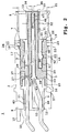
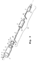
- FIG. 2 shows a triaxial contact 1 according to the invention.
- the triaxial contact 1 includes a first contact 2, an intermediate contact 3 and a central contact 4.
- the triaxial contact 1 also includes a front insulator S and a rear insulator 6.
- the first contact 2 is a hollow cylindrical body.
- the first cylindrical contact 2 has a cavity 7. It particularly has a first rear end 8 and a second front end 9, delimiting the cavity 7.
- the first cylindrical contact 2 has an arm 10.
- the arm 10 stands perpendicularly at an edge 11 of an orifice 12 opening onto the cavity 7. in figure 2, the arm 10 has two teeth 15 and 16.
- the front end 9, the first cylindrical contact 2 has an orifice 13 opening onto the cavity 7.
- the front end 9 has slots 14, shown in figure 3.
- the slots 14 are oriented perpendicular to a plane formed by the orifice 13.
- the front insulator 5 has a generally cylindrical shape.
- the front insulator 5 has a collar 18 on an outer wall 11.
- the collar 18 has a conical shape, one profile thereof being triangular.
- the collar 18 has a certain elasticity.
- the front insulator 5 has an outside diameter 19.
- the first cylindrical contact 2 bas an inside diameter 20.
- the diameter 20 B slightly greater than the diameter 19.
- the orifice 13 bas a diameter 21.
- the diameter 21 is also greater than the outside diameter 19. So, the front insulator 5 may be introduced inside the cylindrical contact 2 from the front end 9, through the orifice 13.
- the collar 18 has an inclined surface such that a diameter of the front insulator 5 is the greatest diameter 22 at the collar 18.
- the diameter 22 is also greater than the inside diameter 20. Therefore, when the front insulator 5 is introduced in the cylindrical contact 2, the collar 18 is forced against the inner walls of the cylindrical contact 2.
- the front insulator 5 B force-fitted in the cavity 7 until the collar 18 engages in a groove 23 of 20 the inner wall of the cylindrical contact 2.
- the groove 23 preferably has a rectangular profile.
- the collar 18 locked in the groove 23 forms a first elastic lock 24. in one variant, as shown in figure 2, the groove 23 may have a profile complementary to the profile of the collar 18.
- said first elastic lock 24 may consist of a collar provided on an inner wall of the cylindrical contact 2, and of a groove provided on an outer wall of the front insulator 5.
- the profile of the elastic lock 15 opposite to the one shown in figure 2. The part with the greater diameter of the collar is then situated on the rear end side 8.
- the collar provided on the cylindrical contact 2 may be a harpoon, which could be embedded in the outer wall of the front insulator 5.
- the front insulator 5 bas a rear end 25 and a front end 26.
- the rear end 25 is on the same side as the rear end 8 of the cylindrical contact 2.
- the front end 26 15 on the same side as the front end 9 of the cylindrical contact 2.
- the front insulator S has a first opening 21 and a second opening 28.
- the openings 27 and 28 do not communicate with each other.
- the first opening 27 opens onto a first receptacle 29, and the second opening 28 opens onto a second receptacle 30.
- the second receptacle 30 is disposed at the center of the front insulator 5, and does not communicate anywhere with the receptacle 29. This allows to ensure insulation between the intermediate contact and the central contact.
- the front insulator 5 has a central cylindrical extension 31.
- the central cylindrical extension 33 has an outside diameter 32.
- the outside diameter 32 is smaller than the diameter 19.
- the central cylindrical extension 31 has an orifice 34 at its end 33.
- the second receptacle 30 ends with the orifice 34.
- the front insulator 5 has a 20 tonic orifice 35.
- This toric orifice 35 encircles the central cylindrical extension 31.
- the toric orifice 35 communicates with the first receptacle 29.
- the first receptacle 29 has a first toric cavity 36 allowing to accommodate a cylinder hollowed out at its center and such that the center of such hollowed-out cylinder may be traversed by Pie central cylindrical extension 31.
- Said toric cavity 36 opens onto a rectangular cavity 37.
- the rectangular cavity 37 in turn opens at the rear end 25 onto the first opening 27.
- the receptacle 29 is thus formed by the toric cavity 36 and the rectangular cavity 37.
- the intermediate contact 3 bas a cylindrical section 38 topped, on an edge 39 thereof, by a pin 40.
- the cylindrical section 38 bas a shape complementary to the toric cavity 36.
- the pin 40 bas a rectangular shape complementary to the rectangular cavity 37.
- the intermediate contact 3 is introduced in the front insulator S from the front end 26 so that the central cylindrical extension 31 engages in the hollow of the cylindrical section 38, that said cylindrical section 38 engages by the toric orifice 35 in the toric cavity 36, and that the pin 40 engages in the rectangular cavity 37.
- the pin 40 projects out of the front insulator 5 through the first opening 27, at the rear end 25.
- the cylindrical section 38 has a protrusion 42 on 10 an outer surface 41.
- the protrusion 42 bas a harpoon-like profile and is rigid.
- the harpoon 42 15 anchored in a wall of the toric cavity 36, when it is introduced in the front insulator 5.
- the harpoon 42 is embedded in the material of the front insulator 5.
- the protrusion 42 may have a profile fit for engagement in a groove 43 provided on an inner face of the toric cavity 36.
- the protrusion 42 is 20 elastic. n this variant, it preferably bas a conic shape and a triangular profile.
- the protrusion 42 and the groove 43 may form an elastic lock 44.
- the lock 44 has the same characteristics as the elastic lock 24.
- the groove may be provided on the outer face of the intermediate contact 3, and the protrusion on an inner wall of the toric cavity 36. In this variant, the greater diameter of the protrusion is provided on the rear end side 25.
- the intermediate contact 3 is held inside the front insulator 5 by being retained by the elastic lock 44. Further, the intermediate contact 3 abuts against a front collar 45 of the orifice 35.
- the central contact 4 also has a cylindrical shape. It particularly comprises a female socket 46.
- the central contact 4 is introduced in the front insulator 5 from the rear end 25 of the front insulator 5.
- the central contact 4 is thus introduced in the front insulator 5 from a side opposite to the side used for introducing the intermediate contact 3.
- the female socket 46 is introduced through the second opening 28.
- the female socket 46 has an orifice 47 having an outside diameter slight]y greater than an opening diameter 48 of the orifice 34.
- the orifice 34 thus allows to introduce a complementary connector for connection of the latter to the female socket 46.
- the central contact 4 has a collar 49. Said collar 49 abuts against a rim of the second opening 28 of the front insulator 5.
- a pin 50 of the central contact 4 extends from the collar 49. The pin 50 is not accommodated in the front insulator 5.
- the rear insulator 6 insulates the pin 40 from the pin 50 and both from the rear end 8 of the first contact 2.
- the rear insulator 6 has therefore a first tunnel 51 and a second tunnel 52.
- the pin 40 of the intermediate contact 3 passes through the first tunnel 51.
- the pin 50 of the central contact 4 passes through the second tunnel 52.
- the pin 50 is angled inside the second tunnel 52.
- the rear insulator 6 is mounted against the first end 25 of the front insulator 5.
- the rear - insulator 6 abuts against an edge 52 of said first end 25.
- such a triaxial contact includes two pins preferably turned in the same direction with respect to a main longitudinal axis of the contact, se that they can be thereafter welded on the same plane.
- the pins 40 and 50 are bent at an angle of 110°.
- the front insulator 5, the rear insulator 6, the intermediate contact 3 and the central contact 4 form an assembly 55.
- This assembly 55 is introduced in the cavity 7 of the first cylindrical contact 2 from the front end 9 of said first contact 2.
- the assembly 55 is slid into the cavity 7, until the collar 18 engages in the groove 23 in such a manner as to mechanically lock it in place, and on the other hand until a side protrusion 56 of the rear insulator 6 abuts against a rim 57 of the inner wall of the first cylindrical contact 2.
- the elastic lock 24 acts as a harpoon.
- a pulling force above 50 daN/mm 2 should be exerted on both parts of the lock.
- the retaining force of the harpoon 42 anchored in the front insulator 5 is of the order of 50 daN.
- the resistance level of the lock and of the anchorage is definitely sufficient for the required use.
- a force exerted on one end of a contact contained in this type of contact is typically lower than 0,5 daN/mm 2 .
Landscapes
- Coupling Device And Connection With Printed Circuit (AREA)
- Connector Housings Or Holding Contact Members (AREA)
- Manufacture Of Switches (AREA)
Applications Claiming Priority (2)
| Application Number | Priority Date | Filing Date | Title |
|---|---|---|---|
| FR9909291 | 1999-07-16 | ||
| FR9909291A FR2796498B1 (fr) | 1999-07-16 | 1999-07-16 | Contact triaxial et procede d'assemblage de ce contact |
Publications (2)
| Publication Number | Publication Date |
|---|---|
| EP1069654A1 true EP1069654A1 (de) | 2001-01-17 |
| EP1069654B1 EP1069654B1 (de) | 2002-10-16 |
Family
ID=9548215
Family Applications (1)
| Application Number | Title | Priority Date | Filing Date |
|---|---|---|---|
| EP00401960A Expired - Lifetime EP1069654B1 (de) | 1999-07-16 | 2000-07-06 | Triaxialverbinder und Verfahren zum Zusammenbau eines solchen Steckverbinders |
Country Status (5)
| Country | Link |
|---|---|
| US (1) | US6443763B1 (de) |
| EP (1) | EP1069654B1 (de) |
| AT (1) | ATE226366T1 (de) |
| DE (1) | DE60000596T2 (de) |
| FR (1) | FR2796498B1 (de) |
Cited By (15)
| Publication number | Priority date | Publication date | Assignee | Title |
|---|---|---|---|---|
| EP1315250A3 (de) * | 2001-11-21 | 2004-01-07 | Fci | Elektrischer Kontaktstift |
| US6692286B1 (en) | 1999-10-22 | 2004-02-17 | Huber + Suhner Ag | Coaxial plug connector |
| US7189097B2 (en) | 2005-02-11 | 2007-03-13 | Winchester Electronics Corporation | Snap lock connector |
| US9722363B2 (en) | 2012-10-16 | 2017-08-01 | Corning Optical Communications Rf Llc | Coaxial cable connector with integral RFI protection |
| US9762008B2 (en) | 2013-05-20 | 2017-09-12 | Corning Optical Communications Rf Llc | Coaxial cable connector with integral RFI protection |
| US9768565B2 (en) | 2012-01-05 | 2017-09-19 | Corning Optical Communications Rf Llc | Quick mount connector for a coaxial cable |
| US9859631B2 (en) | 2011-09-15 | 2018-01-02 | Corning Optical Communications Rf Llc | Coaxial cable connector with integral radio frequency interference and grounding shield |
| US9882320B2 (en) | 2015-11-25 | 2018-01-30 | Corning Optical Communications Rf Llc | Coaxial cable connector |
| US9905959B2 (en) | 2010-04-13 | 2018-02-27 | Corning Optical Communication RF LLC | Coaxial connector with inhibited ingress and improved grounding |
| US9991651B2 (en) | 2014-11-03 | 2018-06-05 | Corning Optical Communications Rf Llc | Coaxial cable connector with post including radially expanding tabs |
| US10033122B2 (en) | 2015-02-20 | 2018-07-24 | Corning Optical Communications Rf Llc | Cable or conduit connector with jacket retention feature |
| US10211547B2 (en) | 2015-09-03 | 2019-02-19 | Corning Optical Communications Rf Llc | Coaxial cable connector |
| US10290958B2 (en) | 2013-04-29 | 2019-05-14 | Corning Optical Communications Rf Llc | Coaxial cable connector with integral RFI protection and biasing ring |
| US10756455B2 (en) | 2005-01-25 | 2020-08-25 | Corning Optical Communications Rf Llc | Electrical connector with grounding member |
| US12034264B2 (en) | 2021-03-31 | 2024-07-09 | Corning Optical Communications Rf Llc | Coaxial cable connector assemblies with outer conductor engagement features and methods for using the same |
Families Citing this family (6)
| Publication number | Priority date | Publication date | Assignee | Title |
|---|---|---|---|---|
| CN2553532Y (zh) * | 2002-06-26 | 2003-05-28 | 章鸿斌 | 一种香蕉插头 |
| TWI256755B (en) * | 2002-11-29 | 2006-06-11 | Hon Hai Prec Ind Co Ltd | Method for assembling electrical connector |
| US7319410B2 (en) | 2004-06-28 | 2008-01-15 | Intelliserv, Inc. | Downhole transmission system |
| US9407016B2 (en) | 2012-02-22 | 2016-08-02 | Corning Optical Communications Rf Llc | Coaxial cable connector with integral continuity contacting portion |
| US9548557B2 (en) | 2013-06-26 | 2017-01-17 | Corning Optical Communications LLC | Connector assemblies and methods of manufacture |
| US9590287B2 (en) | 2015-02-20 | 2017-03-07 | Corning Optical Communications Rf Llc | Surge protected coaxial termination |
Citations (4)
| Publication number | Priority date | Publication date | Assignee | Title |
|---|---|---|---|---|
| US4666231A (en) * | 1986-06-26 | 1987-05-19 | Amp Incorporated | Switching coaxial connector |
| US4674809A (en) * | 1986-01-30 | 1987-06-23 | Amp Incorporated | Filtered triax connector |
| EP0299772A2 (de) * | 1987-07-15 | 1989-01-18 | Amphenol Corporation | Datenbuskontakt |
| EP0350835A2 (de) * | 1988-07-12 | 1990-01-17 | W.L. Gore & Associates GmbH | Elektrischer Steckverbinder |
Family Cites Families (2)
| Publication number | Priority date | Publication date | Assignee | Title |
|---|---|---|---|---|
| US4307926A (en) * | 1979-04-20 | 1981-12-29 | Amp Inc. | Triaxial connector assembly |
| US4519666A (en) * | 1983-08-15 | 1985-05-28 | Allied Corporation | Triaxial electrical connector |
-
1999
- 1999-07-16 FR FR9909291A patent/FR2796498B1/fr not_active Expired - Lifetime
-
2000
- 2000-07-06 EP EP00401960A patent/EP1069654B1/de not_active Expired - Lifetime
- 2000-07-06 AT AT00401960T patent/ATE226366T1/de not_active IP Right Cessation
- 2000-07-06 DE DE60000596T patent/DE60000596T2/de not_active Expired - Fee Related
- 2000-07-13 US US09/615,167 patent/US6443763B1/en not_active Expired - Fee Related
Patent Citations (4)
| Publication number | Priority date | Publication date | Assignee | Title |
|---|---|---|---|---|
| US4674809A (en) * | 1986-01-30 | 1987-06-23 | Amp Incorporated | Filtered triax connector |
| US4666231A (en) * | 1986-06-26 | 1987-05-19 | Amp Incorporated | Switching coaxial connector |
| EP0299772A2 (de) * | 1987-07-15 | 1989-01-18 | Amphenol Corporation | Datenbuskontakt |
| EP0350835A2 (de) * | 1988-07-12 | 1990-01-17 | W.L. Gore & Associates GmbH | Elektrischer Steckverbinder |
Cited By (20)
| Publication number | Priority date | Publication date | Assignee | Title |
|---|---|---|---|---|
| US6692286B1 (en) | 1999-10-22 | 2004-02-17 | Huber + Suhner Ag | Coaxial plug connector |
| EP1315250A3 (de) * | 2001-11-21 | 2004-01-07 | Fci | Elektrischer Kontaktstift |
| US10756455B2 (en) | 2005-01-25 | 2020-08-25 | Corning Optical Communications Rf Llc | Electrical connector with grounding member |
| US7189097B2 (en) | 2005-02-11 | 2007-03-13 | Winchester Electronics Corporation | Snap lock connector |
| US7329139B2 (en) | 2005-02-11 | 2008-02-12 | Winchester Electronics Corporation | Snap lock connector |
| US10312629B2 (en) | 2010-04-13 | 2019-06-04 | Corning Optical Communications Rf Llc | Coaxial connector with inhibited ingress and improved grounding |
| US9905959B2 (en) | 2010-04-13 | 2018-02-27 | Corning Optical Communication RF LLC | Coaxial connector with inhibited ingress and improved grounding |
| US9859631B2 (en) | 2011-09-15 | 2018-01-02 | Corning Optical Communications Rf Llc | Coaxial cable connector with integral radio frequency interference and grounding shield |
| US9768565B2 (en) | 2012-01-05 | 2017-09-19 | Corning Optical Communications Rf Llc | Quick mount connector for a coaxial cable |
| US10236636B2 (en) | 2012-10-16 | 2019-03-19 | Corning Optical Communications Rf Llc | Coaxial cable connector with integral RFI protection |
| US9722363B2 (en) | 2012-10-16 | 2017-08-01 | Corning Optical Communications Rf Llc | Coaxial cable connector with integral RFI protection |
| US9912105B2 (en) | 2012-10-16 | 2018-03-06 | Corning Optical Communications Rf Llc | Coaxial cable connector with integral RFI protection |
| US10290958B2 (en) | 2013-04-29 | 2019-05-14 | Corning Optical Communications Rf Llc | Coaxial cable connector with integral RFI protection and biasing ring |
| US10396508B2 (en) | 2013-05-20 | 2019-08-27 | Corning Optical Communications Rf Llc | Coaxial cable connector with integral RFI protection |
| US9762008B2 (en) | 2013-05-20 | 2017-09-12 | Corning Optical Communications Rf Llc | Coaxial cable connector with integral RFI protection |
| US9991651B2 (en) | 2014-11-03 | 2018-06-05 | Corning Optical Communications Rf Llc | Coaxial cable connector with post including radially expanding tabs |
| US10033122B2 (en) | 2015-02-20 | 2018-07-24 | Corning Optical Communications Rf Llc | Cable or conduit connector with jacket retention feature |
| US10211547B2 (en) | 2015-09-03 | 2019-02-19 | Corning Optical Communications Rf Llc | Coaxial cable connector |
| US9882320B2 (en) | 2015-11-25 | 2018-01-30 | Corning Optical Communications Rf Llc | Coaxial cable connector |
| US12034264B2 (en) | 2021-03-31 | 2024-07-09 | Corning Optical Communications Rf Llc | Coaxial cable connector assemblies with outer conductor engagement features and methods for using the same |
Also Published As
| Publication number | Publication date |
|---|---|
| ATE226366T1 (de) | 2002-11-15 |
| FR2796498A1 (fr) | 2001-01-19 |
| FR2796498B1 (fr) | 2001-11-23 |
| DE60000596D1 (de) | 2002-11-21 |
| EP1069654B1 (de) | 2002-10-16 |
| US6443763B1 (en) | 2002-09-03 |
| DE60000596T2 (de) | 2003-06-05 |
Similar Documents
| Publication | Publication Date | Title |
|---|---|---|
| EP1069654B1 (de) | Triaxialverbinder und Verfahren zum Zusammenbau eines solchen Steckverbinders | |
| US6257918B1 (en) | Wire harness connector having a contact retention plate | |
| EP0079120A1 (de) | Elektrische Verbinder | |
| US20040038596A1 (en) | Plug-in connector with a bushing | |
| US4158473A (en) | Convertible cylindrical electrical connector | |
| US5707259A (en) | Female terminal | |
| JPH07235349A (ja) | スナップ止めにより係止する超小型の同軸コネクター | |
| US20110028048A1 (en) | Electrical connector having an electrical contact with a contact arm | |
| US11070013B2 (en) | Over-molded coaxial connector assembly | |
| US6217381B1 (en) | Connector for a coaxial cable and its connecting method | |
| EP0794596A2 (de) | Steckverbindungsmodul, Steckverbindungsmodulkit und Zusammenbau von Steckverbindungsmodul und Platte | |
| US4682838A (en) | Multipolar plug | |
| EP0803942B1 (de) | Buchse zum Verbinden eines elektrischen Gerätes mit einem Steckverbinder | |
| US6409548B1 (en) | Microelectronic connector with open-cavity insert | |
| US5613879A (en) | Coupling connector to a complementary plug unit | |
| US7887368B1 (en) | Electrical connector having a dielectric insert for retaining an electrical contact | |
| CN100403597C (zh) | 用于具有压接导线的接触件的电连接器单元 | |
| EP1045482A3 (de) | Verbinder | |
| AU615775B2 (en) | Modular jack assembly | |
| US6000966A (en) | Electrical connector with contact terminal locking | |
| CA1282134C (en) | Connector assembly | |
| EP0991138A2 (de) | Elektrischer Verbinder mit Erdungsvorrichtung | |
| US5529518A (en) | Electrical contact assembly | |
| EP0223586A2 (de) | Elektrische Verbinder mit Mehrzweck-Kontakthohlräumen | |
| JPH0317359B2 (de) |
Legal Events
| Date | Code | Title | Description |
|---|---|---|---|
| PUAI | Public reference made under article 153(3) epc to a published international application that has entered the european phase |
Free format text: ORIGINAL CODE: 0009012 |
|
| AK | Designated contracting states |
Kind code of ref document: A1 Designated state(s): AT BE CH CY DE DK ES FI FR GB GR IE IT LI LU MC NL PT SE |
|
| AX | Request for extension of the european patent |
Free format text: AL;LT;LV;MK;RO;SI |
|
| 17P | Request for examination filed |
Effective date: 20010625 |
|
| GRAG | Despatch of communication of intention to grant |
Free format text: ORIGINAL CODE: EPIDOS AGRA |
|
| AKX | Designation fees paid |
Free format text: AT BE CH CY DE DK ES FI FR GB GR IE IT LI LU MC NL PT SE |
|
| 17Q | First examination report despatched |
Effective date: 20011010 |
|
| GRAG | Despatch of communication of intention to grant |
Free format text: ORIGINAL CODE: EPIDOS AGRA |
|
| GRAH | Despatch of communication of intention to grant a patent |
Free format text: ORIGINAL CODE: EPIDOS IGRA |
|
| GRAH | Despatch of communication of intention to grant a patent |
Free format text: ORIGINAL CODE: EPIDOS IGRA |
|
| RAP1 | Party data changed (applicant data changed or rights of an application transferred) |
Owner name: FCI |
|
| GRAA | (expected) grant |
Free format text: ORIGINAL CODE: 0009210 |
|
| AK | Designated contracting states |
Kind code of ref document: B1 Designated state(s): AT BE CH CY DE DK ES FI FR GB GR IE IT LI LU MC NL PT SE |
|
| PG25 | Lapsed in a contracting state [announced via postgrant information from national office to epo] |
Ref country code: NL Free format text: LAPSE BECAUSE OF FAILURE TO SUBMIT A TRANSLATION OF THE DESCRIPTION OR TO PAY THE FEE WITHIN THE PRESCRIBED TIME-LIMIT Effective date: 20021016 Ref country code: LI Free format text: LAPSE BECAUSE OF FAILURE TO SUBMIT A TRANSLATION OF THE DESCRIPTION OR TO PAY THE FEE WITHIN THE PRESCRIBED TIME-LIMIT Effective date: 20021016 Ref country code: IT Free format text: LAPSE BECAUSE OF FAILURE TO SUBMIT A TRANSLATION OF THE DESCRIPTION OR TO PAY THE FEE WITHIN THE PRESCRIBED TIME-LIMIT;WARNING: LAPSES OF ITALIAN PATENTS WITH EFFECTIVE DATE BEFORE 2007 MAY HAVE OCCURRED AT ANY TIME BEFORE 2007. THE CORRECT EFFECTIVE DATE MAY BE DIFFERENT FROM THE ONE RECORDED. Effective date: 20021016 Ref country code: GR Free format text: LAPSE BECAUSE OF FAILURE TO SUBMIT A TRANSLATION OF THE DESCRIPTION OR TO PAY THE FEE WITHIN THE PRESCRIBED TIME-LIMIT Effective date: 20021016 Ref country code: FI Free format text: LAPSE BECAUSE OF FAILURE TO SUBMIT A TRANSLATION OF THE DESCRIPTION OR TO PAY THE FEE WITHIN THE PRESCRIBED TIME-LIMIT Effective date: 20021016 Ref country code: CH Free format text: LAPSE BECAUSE OF FAILURE TO SUBMIT A TRANSLATION OF THE DESCRIPTION OR TO PAY THE FEE WITHIN THE PRESCRIBED TIME-LIMIT Effective date: 20021016 Ref country code: BE Free format text: LAPSE BECAUSE OF FAILURE TO SUBMIT A TRANSLATION OF THE DESCRIPTION OR TO PAY THE FEE WITHIN THE PRESCRIBED TIME-LIMIT Effective date: 20021016 Ref country code: AT Free format text: LAPSE BECAUSE OF FAILURE TO SUBMIT A TRANSLATION OF THE DESCRIPTION OR TO PAY THE FEE WITHIN THE PRESCRIBED TIME-LIMIT Effective date: 20021016 |
|
| REF | Corresponds to: |
Ref document number: 226366 Country of ref document: AT Date of ref document: 20021115 Kind code of ref document: T |
|
| REG | Reference to a national code |
Ref country code: GB Ref legal event code: FG4D |
|
| REG | Reference to a national code |
Ref country code: CH Ref legal event code: EP |
|
| REG | Reference to a national code |
Ref country code: IE Ref legal event code: FG4D |
|
| REF | Corresponds to: |
Ref document number: 60000596 Country of ref document: DE Date of ref document: 20021121 |
|
| ET | Fr: translation filed | ||
| PG25 | Lapsed in a contracting state [announced via postgrant information from national office to epo] |
Ref country code: SE Free format text: LAPSE BECAUSE OF FAILURE TO SUBMIT A TRANSLATION OF THE DESCRIPTION OR TO PAY THE FEE WITHIN THE PRESCRIBED TIME-LIMIT Effective date: 20030116 Ref country code: PT Free format text: LAPSE BECAUSE OF FAILURE TO SUBMIT A TRANSLATION OF THE DESCRIPTION OR TO PAY THE FEE WITHIN THE PRESCRIBED TIME-LIMIT Effective date: 20030116 Ref country code: DK Free format text: LAPSE BECAUSE OF FAILURE TO SUBMIT A TRANSLATION OF THE DESCRIPTION OR TO PAY THE FEE WITHIN THE PRESCRIBED TIME-LIMIT Effective date: 20030116 |
|
| NLV1 | Nl: lapsed or annulled due to failure to fulfill the requirements of art. 29p and 29m of the patents act | ||
| PG25 | Lapsed in a contracting state [announced via postgrant information from national office to epo] |
Ref country code: ES Free format text: LAPSE BECAUSE OF FAILURE TO SUBMIT A TRANSLATION OF THE DESCRIPTION OR TO PAY THE FEE WITHIN THE PRESCRIBED TIME-LIMIT Effective date: 20030429 |
|
| REG | Reference to a national code |
Ref country code: CH Ref legal event code: PL |
|
| PG25 | Lapsed in a contracting state [announced via postgrant information from national office to epo] |
Ref country code: LU Free format text: LAPSE BECAUSE OF NON-PAYMENT OF DUE FEES Effective date: 20030706 Ref country code: CY Free format text: LAPSE BECAUSE OF FAILURE TO SUBMIT A TRANSLATION OF THE DESCRIPTION OR TO PAY THE FEE WITHIN THE PRESCRIBED TIME-LIMIT Effective date: 20030706 |
|
| PG25 | Lapsed in a contracting state [announced via postgrant information from national office to epo] |
Ref country code: IE Free format text: LAPSE BECAUSE OF NON-PAYMENT OF DUE FEES Effective date: 20030707 |
|
| PG25 | Lapsed in a contracting state [announced via postgrant information from national office to epo] |
Ref country code: MC Free format text: LAPSE BECAUSE OF NON-PAYMENT OF DUE FEES Effective date: 20030731 |
|
| PLBE | No opposition filed within time limit |
Free format text: ORIGINAL CODE: 0009261 |
|
| STAA | Information on the status of an ep patent application or granted ep patent |
Free format text: STATUS: NO OPPOSITION FILED WITHIN TIME LIMIT |
|
| PGFP | Annual fee paid to national office [announced via postgrant information from national office to epo] |
Ref country code: DE Payment date: 20030929 Year of fee payment: 4 |
|
| 26N | No opposition filed |
Effective date: 20030717 |
|
| REG | Reference to a national code |
Ref country code: IE Ref legal event code: MM4A |
|
| PG25 | Lapsed in a contracting state [announced via postgrant information from national office to epo] |
Ref country code: GB Free format text: LAPSE BECAUSE OF NON-PAYMENT OF DUE FEES Effective date: 20040706 |
|
| PGFP | Annual fee paid to national office [announced via postgrant information from national office to epo] |
Ref country code: FR Payment date: 20040811 Year of fee payment: 5 |
|
| PG25 | Lapsed in a contracting state [announced via postgrant information from national office to epo] |
Ref country code: DE Free format text: LAPSE BECAUSE OF NON-PAYMENT OF DUE FEES Effective date: 20050201 |
|
| GBPC | Gb: european patent ceased through non-payment of renewal fee |
Effective date: 20040706 |
|
| PG25 | Lapsed in a contracting state [announced via postgrant information from national office to epo] |
Ref country code: FR Free format text: LAPSE BECAUSE OF NON-PAYMENT OF DUE FEES Effective date: 20060331 |
|
| REG | Reference to a national code |
Ref country code: FR Ref legal event code: ST Effective date: 20060331 |