EP1069631B1 - Battery pack and method for constructing same - Google Patents
Battery pack and method for constructing same Download PDFInfo
- Publication number
- EP1069631B1 EP1069631B1 EP20000306010 EP00306010A EP1069631B1 EP 1069631 B1 EP1069631 B1 EP 1069631B1 EP 20000306010 EP20000306010 EP 20000306010 EP 00306010 A EP00306010 A EP 00306010A EP 1069631 B1 EP1069631 B1 EP 1069631B1
- Authority
- EP
- European Patent Office
- Prior art keywords
- battery pack
- supports
- cell
- cells
- support
- Prior art date
- Legal status (The legal status is an assumption and is not a legal conclusion. Google has not performed a legal analysis and makes no representation as to the accuracy of the status listed.)
- Expired - Lifetime
Links
- 238000000034 method Methods 0.000 title claims description 12
- 239000012530 fluid Substances 0.000 claims abstract description 8
- 238000004519 manufacturing process Methods 0.000 claims description 2
- 238000007792 addition Methods 0.000 description 1
- 230000004075 alteration Effects 0.000 description 1
- OJIJEKBXJYRIBZ-UHFFFAOYSA-N cadmium nickel Chemical compound [Ni].[Cd] OJIJEKBXJYRIBZ-UHFFFAOYSA-N 0.000 description 1
- 239000003990 capacitor Substances 0.000 description 1
- 238000001816 cooling Methods 0.000 description 1
- 239000012809 cooling fluid Substances 0.000 description 1
- 238000010168 coupling process Methods 0.000 description 1
- 238000005859 coupling reaction Methods 0.000 description 1
- 238000005520 cutting process Methods 0.000 description 1
- 238000010586 diagram Methods 0.000 description 1
- 239000003792 electrolyte Substances 0.000 description 1
- 239000003292 glue Substances 0.000 description 1
- 238000003780 insertion Methods 0.000 description 1
- 230000037431 insertion Effects 0.000 description 1
- 230000003993 interaction Effects 0.000 description 1
- 239000007788 liquid Substances 0.000 description 1
- 239000000463 material Substances 0.000 description 1
- 229910052987 metal hydride Inorganic materials 0.000 description 1
- 238000012544 monitoring process Methods 0.000 description 1
- 238000003466 welding Methods 0.000 description 1
Images


Classifications
-
- H—ELECTRICITY
- H01—ELECTRIC ELEMENTS
- H01M—PROCESSES OR MEANS, e.g. BATTERIES, FOR THE DIRECT CONVERSION OF CHEMICAL ENERGY INTO ELECTRICAL ENERGY
- H01M10/00—Secondary cells; Manufacture thereof
- H01M10/42—Methods or arrangements for servicing or maintenance of secondary cells or secondary half-cells
- H01M10/46—Accumulators structurally combined with charging apparatus
-
- H—ELECTRICITY
- H01—ELECTRIC ELEMENTS
- H01M—PROCESSES OR MEANS, e.g. BATTERIES, FOR THE DIRECT CONVERSION OF CHEMICAL ENERGY INTO ELECTRICAL ENERGY
- H01M10/00—Secondary cells; Manufacture thereof
- H01M10/60—Heating or cooling; Temperature control
- H01M10/61—Types of temperature control
- H01M10/613—Cooling or keeping cold
-
- H—ELECTRICITY
- H01—ELECTRIC ELEMENTS
- H01M—PROCESSES OR MEANS, e.g. BATTERIES, FOR THE DIRECT CONVERSION OF CHEMICAL ENERGY INTO ELECTRICAL ENERGY
- H01M10/00—Secondary cells; Manufacture thereof
- H01M10/60—Heating or cooling; Temperature control
- H01M10/62—Heating or cooling; Temperature control specially adapted for specific applications
- H01M10/623—Portable devices, e.g. mobile telephones, cameras or pacemakers
- H01M10/6235—Power tools
-
- H—ELECTRICITY
- H01—ELECTRIC ELEMENTS
- H01M—PROCESSES OR MEANS, e.g. BATTERIES, FOR THE DIRECT CONVERSION OF CHEMICAL ENERGY INTO ELECTRICAL ENERGY
- H01M10/00—Secondary cells; Manufacture thereof
- H01M10/60—Heating or cooling; Temperature control
- H01M10/64—Heating or cooling; Temperature control characterised by the shape of the cells
- H01M10/643—Cylindrical cells
-
- H—ELECTRICITY
- H01—ELECTRIC ELEMENTS
- H01M—PROCESSES OR MEANS, e.g. BATTERIES, FOR THE DIRECT CONVERSION OF CHEMICAL ENERGY INTO ELECTRICAL ENERGY
- H01M10/00—Secondary cells; Manufacture thereof
- H01M10/60—Heating or cooling; Temperature control
- H01M10/65—Means for temperature control structurally associated with the cells
- H01M10/656—Means for temperature control structurally associated with the cells characterised by the type of heat-exchange fluid
- H01M10/6561—Gases
- H01M10/6562—Gases with free flow by convection only
-
- H—ELECTRICITY
- H01—ELECTRIC ELEMENTS
- H01M—PROCESSES OR MEANS, e.g. BATTERIES, FOR THE DIRECT CONVERSION OF CHEMICAL ENERGY INTO ELECTRICAL ENERGY
- H01M10/00—Secondary cells; Manufacture thereof
- H01M10/60—Heating or cooling; Temperature control
- H01M10/65—Means for temperature control structurally associated with the cells
- H01M10/656—Means for temperature control structurally associated with the cells characterised by the type of heat-exchange fluid
- H01M10/6561—Gases
- H01M10/6566—Means within the gas flow to guide the flow around one or more cells, e.g. manifolds, baffles or other barriers
-
- H—ELECTRICITY
- H01—ELECTRIC ELEMENTS
- H01M—PROCESSES OR MEANS, e.g. BATTERIES, FOR THE DIRECT CONVERSION OF CHEMICAL ENERGY INTO ELECTRICAL ENERGY
- H01M50/00—Constructional details or processes of manufacture of the non-active parts of electrochemical cells other than fuel cells, e.g. hybrid cells
- H01M50/20—Mountings; Secondary casings or frames; Racks, modules or packs; Suspension devices; Shock absorbers; Transport or carrying devices; Holders
- H01M50/204—Racks, modules or packs for multiple batteries or multiple cells
- H01M50/207—Racks, modules or packs for multiple batteries or multiple cells characterised by their shape
- H01M50/213—Racks, modules or packs for multiple batteries or multiple cells characterised by their shape adapted for cells having curved cross-section, e.g. round or elliptic
-
- H—ELECTRICITY
- H01—ELECTRIC ELEMENTS
- H01M—PROCESSES OR MEANS, e.g. BATTERIES, FOR THE DIRECT CONVERSION OF CHEMICAL ENERGY INTO ELECTRICAL ENERGY
- H01M50/00—Constructional details or processes of manufacture of the non-active parts of electrochemical cells other than fuel cells, e.g. hybrid cells
- H01M50/50—Current conducting connections for cells or batteries
- H01M50/502—Interconnectors for connecting terminals of adjacent batteries; Interconnectors for connecting cells outside a battery casing
- H01M50/503—Interconnectors for connecting terminals of adjacent batteries; Interconnectors for connecting cells outside a battery casing characterised by the shape of the interconnectors
-
- H—ELECTRICITY
- H01—ELECTRIC ELEMENTS
- H01M—PROCESSES OR MEANS, e.g. BATTERIES, FOR THE DIRECT CONVERSION OF CHEMICAL ENERGY INTO ELECTRICAL ENERGY
- H01M50/00—Constructional details or processes of manufacture of the non-active parts of electrochemical cells other than fuel cells, e.g. hybrid cells
- H01M50/50—Current conducting connections for cells or batteries
- H01M50/572—Means for preventing undesired use or discharge
- H01M50/574—Devices or arrangements for the interruption of current
- H01M50/581—Devices or arrangements for the interruption of current in response to temperature
-
- H—ELECTRICITY
- H01—ELECTRIC ELEMENTS
- H01M—PROCESSES OR MEANS, e.g. BATTERIES, FOR THE DIRECT CONVERSION OF CHEMICAL ENERGY INTO ELECTRICAL ENERGY
- H01M10/00—Secondary cells; Manufacture thereof
- H01M10/42—Methods or arrangements for servicing or maintenance of secondary cells or secondary half-cells
- H01M10/4235—Safety or regulating additives or arrangements in electrodes, separators or electrolyte
-
- H—ELECTRICITY
- H01—ELECTRIC ELEMENTS
- H01M—PROCESSES OR MEANS, e.g. BATTERIES, FOR THE DIRECT CONVERSION OF CHEMICAL ENERGY INTO ELECTRICAL ENERGY
- H01M50/00—Constructional details or processes of manufacture of the non-active parts of electrochemical cells other than fuel cells, e.g. hybrid cells
- H01M50/50—Current conducting connections for cells or batteries
-
- H—ELECTRICITY
- H01—ELECTRIC ELEMENTS
- H01M—PROCESSES OR MEANS, e.g. BATTERIES, FOR THE DIRECT CONVERSION OF CHEMICAL ENERGY INTO ELECTRICAL ENERGY
- H01M6/00—Primary cells; Manufacture thereof
- H01M6/42—Grouping of primary cells into batteries
-
- Y—GENERAL TAGGING OF NEW TECHNOLOGICAL DEVELOPMENTS; GENERAL TAGGING OF CROSS-SECTIONAL TECHNOLOGIES SPANNING OVER SEVERAL SECTIONS OF THE IPC; TECHNICAL SUBJECTS COVERED BY FORMER USPC CROSS-REFERENCE ART COLLECTIONS [XRACs] AND DIGESTS
- Y02—TECHNOLOGIES OR APPLICATIONS FOR MITIGATION OR ADAPTATION AGAINST CLIMATE CHANGE
- Y02E—REDUCTION OF GREENHOUSE GAS [GHG] EMISSIONS, RELATED TO ENERGY GENERATION, TRANSMISSION OR DISTRIBUTION
- Y02E60/00—Enabling technologies; Technologies with a potential or indirect contribution to GHG emissions mitigation
- Y02E60/10—Energy storage using batteries
Definitions
- This invention relates generally to battery packs and, more particularly, to battery packs for cordless power tools.
- Cordless products which use rechargeable batteries are prevalent throughout the workplace as well as in the home. From housewares to power tools, rechargeable batteries are used in numerous devices. Ordinarily, nickel-cadmium or nickel-metal hydride battery cells are used in these devices. Since the devices use a plurality of battery cells, the battery cells are ordinarily packaged as battery packs. These battery packs couple with the cordless devices and secure to the device. The battery pack may be removed from the cordless device and charged in a battery charger or charged in the cordless device itself.
- EP-A-0875 948 which is considered to be the closest prior art, discloses (see Figure 1) a battery pack including two cells, and upper and lower supports at either end of the cells.
- the ends of the cells locate in each support by means of flanges around the periphery of the supports, which retain the cells in position in the battery pack.
- the upper support includes an elongate locking member having a locking element disposed at its distal end. The locking element locates in slot of the lower support, in order to lock the first and second supports in position relative to each other and thereby retain the cells in position.
- a battery pack comprising: a first cell having top and bottom terminals, a first support disposed on the top terminal; and a second support disposed on the bottom terminal, characterised in that the first support comprises a first protrusion, and the second support comprises a second protrusion which engages the first protrusion to lock the first and second supports together.
- a method for manufacturing a battery pack comprising: providing first and second supports and first and second cells, the first and second cells having top and bottom terminals, disposing the first and second cells between the first and second supports, each top and bottom terminals of the first and second cells contacting one of the first and second supports, characterised in that a first protrusion is provided on the first support which engages a second protrusion provided on the second support, to lock the first and second supports together.
- At least one of the first and second supports may include a rib for maintaining the first cell in place.
- the rib may extend along a longitudinal axis of the first cell and/or extend substantially perpendicularly from the at least one of the first and second supports.
- the battery pack may also include a pad disposed on at least one of the top and bottom terminals. The pad may be substantially circular.
- the battery pack may also include a second cell disposed between the first and second supports. The second cell may be disposed adjacent and/or separate to the first cell.
- the battery pack may also include a lead plate connecting the first and second cells. The lead plate may connect the first and second cells through one of the first and second supports. At least one of the first and second supports may have a hole for allowing a fluid to flow therethrough.
- the battery pack may also include a housing supporting the first cell and the first and second supports.
- a battery pack 10 of the present invention is connected to a power tool 100, such as a drill, a miter saw, a circular saw, etc.
- Power tool 100 may have a tool 103, such as a blade, cutting tool or bit, a motor 101 for driving tool 103, and a switch 102 for switching motor 101.
- Motor 101 may be electrically connected to battery pack 10.
- Battery pack 10 preferably includes four battery terminals.
- the first battery terminal POS is the positive terminal for battery pack 10.
- the second battery terminal NEG is the negative/common terminal.
- the third battery terminal TEMP is the temperature terminal.
- the fourth battery terminal ID is the identification terminal.
- Battery terminals POS and NEG receive the charging current sent from a charger (not shown) for charging the battery pack 10.
- Battery cells 21 are coupled between the battery terminals POS and NEG.
- a temperature sensing device such as a negative temperature co-efficient (NTC) resistor, or thermistor, R T .
- the temperature sensing device R T is preferably in close physical proximity to the cells 21 for monitoring of the battery temperature.
- NTC negative temperature co-efficient
- other components such as capacitors, etc., or circuits can be used to provide a signal representative of the battery temperature.
- a battery identification device may be connected to the ID terminal to provide battery identification information to the charger 21.
- the battery identification device 17 is a resistor R ID connected between the ID terminal and the negative terminal NEG.
- the value of resistor R ID is preferably selected to indicate the type and capacity of battery pack 10. Because of the resistance of resistor R ID , the charger can recognize the type and/or capacity of battery pack 10 and modify any and/or all charging parameters, such as charging voltage, current and time, in order to minimize charging time and/or avoid overcharging.
- any and/or all charging parameters such as charging voltage, current and time
- the battery pack 10 comprises at least one packet 20, as shown in FIGS. 1-3.
- Packet 20 may comprise at least one cell 21, and preferably a plurality of cells 21.
- Each cell 21 has a positive terminal 21P and a negative terminal 21N.
- Top and bottom supports 22T, 22B may hold the cells 21 therebetween.
- Supports 22T, 22B may be substantially planar and/or substantially perpendicular to the longitudinal axis of cells 21.
- the supports 22T, 22B have ribs 22R for holding the cells 21 in place and/or for holding the cells 21 apart from each other, as discussed below.
- Supports 22T, 22B may have plate holes 27, exposing the positive and negative terminals 21P, 21N of cells 21.
- Lead plates 23 can be inserted through plate holes 27, and connected to the cell terminals by welding or some other process. If a series connection between two cells is desired, it is preferable to provide alternating terminals, i.e., the top terminal of the first cell is positive while the top terminal of the second cell is negative, in order to simplify connection with lead plates 23. Conversely, if a parallel connection between two cells is desired, it is preferable to provide the cells in the same orientation, so that the top terminals of the first and second cells are next to each other.
- a rib 22R may have a crush rib 22RR for minimizing the play between the cell 21 and rib 22R, thus limiting the movement of cell 21.
- Persons skilled in the art will recognize that other methods for minimizing the play between cell 21 and rib 22R may be used, such as using friction fits or springs, etc.
- pads 24 may be desired to dispose pads 24 between cells 21 and supports 22.
- pads 24 are made of absorptive material.
- Pads 24 may cover part, if not all, of a cell terminal, or a vent hole, of cell 21. By disposing pads 24 accordingly, pads 24 may absorb any electrolyte which may leak from the cell 21.
- pads 24 do not extend beyond the cell terminal, so as to not block holes 22H. Accordingly, pads 24 are preferably circular, and may have a radius substantially equal to or smaller than the radius of cell 21. It is preferable to dispose pads 24 only against vent holes, which may be proximate to positive terminals 21P, or against positive terminals 21P.
- Supports 22T, 22B may have protrusions 25, 26 extending therefrom.
- protrusions 25, 26 extend substantially perpendicular to the supports 22.
- Protrusions 25, 26 may have respective ends 25E, 26E which engage each other.
- end 25E has a hook portion 25H, which engages a hole 26H in end portion 26E, creating a snap-lock junction.
- the junction will slightly compress or hold tightly cells 21, pads 24, etc.
- Persons skilled in the art will recognize that other types of junction may be used, including, for example, male-female socket junctions, friction-coupling junctions, etc.
- a support such as bottom support 22B, is provided. If pads 24 are provided for covering the positive and/or negative terminals, the pads 24 are disposed on support 22B in the appropriate pattern. Cells 21 are then disposed thereon in the desired pattern. More pads 24 may be disposed on cells 21.
- the other support i.e., top support 22T, is disposed on cells 21 and/or pads 24. Both supports 22T, 22B are pushed towards each other, preferably obtaining the snap-lock junction between protrusions 25, 26. Lead plates 23 are then inserted through plate holes 27 (and through pad hole 24H, if necessary), and connected to the cell terminals.
- a lead plate 23 can be connected to a cell 21.
- a pad 24 may then be disposed on cell 21.
- This assembly can then be installed in one of the supports 22T, 22B, where the lead plate 23 extends through plate hole 27.
- the lead plate 23 can then be connected to another cell 21.
- the other of the supports 22T, 22B is then disposed on the cells 21. Lead plates 23 are then connected accordingly.
- the packet 20 can then be inserted into battery pack housing 11.
- housing 11 has ribs 11R to guide insertion of packet 20 into housing 11 and/or to maintain packet 20 in place.
- FIG. 2 shows a clamshell housing 11, which includes two halves, and that one of the halves is not shown. Nevertheless, persons skilled in the art will know to provide the second half, and to fixedly attach both halves together via screws, snap-lock junctions, glue, etc.
- the packet 20 is preferably connected to terminal block 12, which is also disposed in housing 11.
- Terminal block 12 may have multiple terminals 12T, which may correspond to terminals POS, NEG, ID and/or TEMP. If multiple packets 20 are installed within housing 11, the packets 20 need to be electrically connected to each other via wires, lead plates, pressure connectors, etc., and/or to terminal block 12.
- supports 22T, 22B may also have holes 22H, which allow a fluid, either liquid or gaseous, such as air, to flow therethrough.
- ribs 22R are preferably used to maintain cells 21 separated. The fluid can thus flow into packet 20 through a support 22 via holes 22H, between cells 21, and out of packet 20 via holes 22H on the other support 22.
- Persons skilled in the art are referred to US Application No. 09/035,586, filed March 5, 1998, entitled “Battery Cooling System", which is wholly incorporated herein by reference.
- housing 11 is provided with holes 13, for letting air into housing 11 (airflow AIN), which flows through packets 20 as explained above, and out of housing 11 (airflow AOUT), as shown in FIG. 3.
- airflow AIN airflow AIN
- the air may enter through the top of battery pack 10 and exit through holes 13.
Landscapes
- Chemical & Material Sciences (AREA)
- Chemical Kinetics & Catalysis (AREA)
- Electrochemistry (AREA)
- General Chemical & Material Sciences (AREA)
- Engineering & Computer Science (AREA)
- Manufacturing & Machinery (AREA)
- Life Sciences & Earth Sciences (AREA)
- Biophysics (AREA)
- Battery Mounting, Suspending (AREA)
- Blow-Moulding Or Thermoforming Of Plastics Or The Like (AREA)
- Connection Of Batteries Or Terminals (AREA)
- Secondary Cells (AREA)
Abstract
Description
- This invention relates generally to battery packs and, more particularly, to battery packs for cordless power tools.
- Cordless products which use rechargeable batteries are prevalent throughout the workplace as well as in the home. From housewares to power tools, rechargeable batteries are used in numerous devices. Ordinarily, nickel-cadmium or nickel-metal hydride battery cells are used in these devices. Since the devices use a plurality of battery cells, the battery cells are ordinarily packaged as battery packs. These battery packs couple with the cordless devices and secure to the device. The battery pack may be removed from the cordless device and charged in a battery charger or charged in the cordless device itself.
- EP-A-0875 948, which is considered to be the closest prior art, discloses (see Figure 1) a battery pack including two cells, and upper and lower supports at either end of the cells. The ends of the cells locate in each support by means of flanges around the periphery of the supports, which retain the cells in position in the battery pack. The upper support includes an elongate locking member having a locking element disposed at its distal end. The locking element locates in slot of the lower support, in order to lock the first and second supports in position relative to each other and thereby retain the cells in position.
- Because multiple cells are typically used in a battery pack, it may be difficult to assemble the battery pack. It is therefore an object of this invention to provide a battery pack that is easy to assemble.
- In accordance with a first aspect of the present invention, there is provided a battery pack comprising: a first cell having top and bottom terminals, a first support disposed on the top terminal; and a second support disposed on the bottom terminal, characterised in that the first support comprises a first protrusion, and the second support comprises a second protrusion which engages the first protrusion to lock the first and second supports together.
- In accordance with a second aspect of the present invention, there is provided a method for manufacturing a battery pack, comprising: providing first and second supports and first and second cells, the first and second cells having top and bottom terminals, disposing the first and second cells between the first and second supports, each top and bottom terminals of the first and second cells contacting one of the first and second supports, characterised in that a first protrusion is provided on the first support which engages a second protrusion provided on the second support, to lock the first and second supports together.
- At least one of the first and second supports may include a rib for maintaining the first cell in place. The rib may extend along a longitudinal axis of the first cell and/or extend substantially perpendicularly from the at least one of the first and second supports. The battery pack may also include a pad disposed on at least one of the top and bottom terminals. The pad may be substantially circular. The battery pack may also include a second cell disposed between the first and second supports. The second cell may be disposed adjacent and/or separate to the first cell. The battery pack may also include a lead plate connecting the first and second cells. The lead plate may connect the first and second cells through one of the first and second supports. At least one of the first and second supports may have a hole for allowing a fluid to flow therethrough. The battery pack may also include a housing supporting the first cell and the first and second supports.
- Additional features and benefits of the present invention are described, and will be apparent from, the accompanying drawings and the detailed description below.
- The accompanying drawings illustrate preferred embodiments of the invention according to the practical application of the principles thereof, and in which:
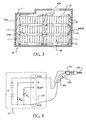
- FIG. 1 is an exploded perspective view of a packet;
- FIG. 2 is a partial exploded perspective view of a battery pack;
- FIG. 3 is a cross-sectional side view of a battery pack; and
- FIG. 4 is a schematic diagram of the battery pack.
- The invention is now described with reference to the accompanying figures, wherein like numerals designate like parts. Referring to FIGS. 1-4, a
battery pack 10 of the present invention is connected to apower tool 100, such as a drill, a miter saw, a circular saw, etc.Power tool 100 may have atool 103, such as a blade, cutting tool or bit, amotor 101 fordriving tool 103, and aswitch 102 for switchingmotor 101. Motor 101 may be electrically connected tobattery pack 10. -
Battery pack 10 preferably includes four battery terminals. The first battery terminal POS is the positive terminal forbattery pack 10. The second battery terminal NEG is the negative/common terminal. The third battery terminal TEMP is the temperature terminal. The fourth battery terminal ID is the identification terminal. Battery terminals POS and NEG receive the charging current sent from a charger (not shown) for charging thebattery pack 10. -
Battery cells 21 are coupled between the battery terminals POS and NEG. In addition, preferably coupled between battery terminals TEMP and NEG is a temperature sensing device, such as a negative temperature co-efficient (NTC) resistor, or thermistor, RT. The temperature sensing device RT is preferably in close physical proximity to thecells 21 for monitoring of the battery temperature. Persons skilled in the art will recognize that other components, such as capacitors, etc., or circuits can be used to provide a signal representative of the battery temperature. - A battery identification device may be connected to the ID terminal to provide battery identification information to the
charger 21. Preferably, the battery identification device 17 is a resistor RID connected between the ID terminal and the negative terminal NEG. The value of resistor RID is preferably selected to indicate the type and capacity ofbattery pack 10. Because of the resistance of resistor RID, the charger can recognize the type and/or capacity ofbattery pack 10 and modify any and/or all charging parameters, such as charging voltage, current and time, in order to minimize charging time and/or avoid overcharging. For further information onbattery pack 10 and the interaction with the charger, persons skilled in the art are referred to US Application No. 09/292164, filed on April 15, 1999, entitled "Method and Apparatus for Charging Batteries," which is hereby incorporated by reference in whole. - Preferably, the
battery pack 10 comprises at least onepacket 20, as shown in FIGS. 1-3.Packet 20 may comprise at least onecell 21, and preferably a plurality ofcells 21. Eachcell 21 has apositive terminal 21P and a negative terminal 21N. - Top and bottom supports 22T, 22B may hold the
cells 21 therebetween.Supports cells 21. Preferably, thesupports ribs 22R for holding thecells 21 in place and/or for holding thecells 21 apart from each other, as discussed below. -
Supports plate holes 27, exposing the positive andnegative terminals 21P, 21N ofcells 21.Lead plates 23 can be inserted throughplate holes 27, and connected to the cell terminals by welding or some other process. If a series connection between two cells is desired, it is preferable to provide alternating terminals, i.e., the top terminal of the first cell is positive while the top terminal of the second cell is negative, in order to simplify connection withlead plates 23. Conversely, if a parallel connection between two cells is desired, it is preferable to provide the cells in the same orientation, so that the top terminals of the first and second cells are next to each other. - It is preferable to minimize movements between
cells 21 relative tolead plates 23. Accordingly, arib 22R may have a crush rib 22RR for minimizing the play between thecell 21 andrib 22R, thus limiting the movement ofcell 21. Persons skilled in the art will recognize that other methods for minimizing the play betweencell 21 andrib 22R may be used, such as using friction fits or springs, etc. - It may be desired to dispose
pads 24 betweencells 21 and supports 22. Preferablypads 24 are made of absorptive material.Pads 24 may cover part, if not all, of a cell terminal, or a vent hole, ofcell 21. By disposingpads 24 accordingly,pads 24 may absorb any electrolyte which may leak from thecell 21. Preferably,pads 24 do not extend beyond the cell terminal, so as to not blockholes 22H. Accordingly,pads 24 are preferably circular, and may have a radius substantially equal to or smaller than the radius ofcell 21. It is preferable to disposepads 24 only against vent holes, which may be proximate topositive terminals 21P, or againstpositive terminals 21P. -
Supports protrusions supports 22.Protrusions respective ends hook portion 25H, which engages ahole 26H inend portion 26E, creating a snap-lock junction. Preferably, the junction will slightly compress or hold tightlycells 21,pads 24, etc. Persons skilled in the art will recognize that other types of junction may be used, including, for example, male-female socket junctions, friction-coupling junctions, etc. - Accordingly, to assemble a
packet 20, a support, such asbottom support 22B, is provided. Ifpads 24 are provided for covering the positive and/or negative terminals, thepads 24 are disposed onsupport 22B in the appropriate pattern.Cells 21 are then disposed thereon in the desired pattern.More pads 24 may be disposed oncells 21. The other support, i.e.,top support 22T, is disposed oncells 21 and/orpads 24. Both supports 22T, 22B are pushed towards each other, preferably obtaining the snap-lock junction betweenprotrusions plates 23 are then inserted through plate holes 27 (and throughpad hole 24H, if necessary), and connected to the cell terminals. - Alternatively, a
lead plate 23 can be connected to acell 21. Apad 24 may then be disposed oncell 21. This assembly can then be installed in one of thesupports lead plate 23 extends throughplate hole 27. Thelead plate 23 can then be connected to anothercell 21. The other of thesupports cells 21. Leadplates 23 are then connected accordingly. - As shown in FIG. 2, the
packet 20 can then be inserted intobattery pack housing 11. Preferably,housing 11 hasribs 11R to guide insertion ofpacket 20 intohousing 11 and/or to maintainpacket 20 in place. Persons skilled in the art will recognize that FIG. 2 shows aclamshell housing 11, which includes two halves, and that one of the halves is not shown. Nevertheless, persons skilled in the art will know to provide the second half, and to fixedly attach both halves together via screws, snap-lock junctions, glue, etc. - The
packet 20 is preferably connected toterminal block 12, which is also disposed inhousing 11.Terminal block 12 may havemultiple terminals 12T, which may correspond to terminals POS, NEG, ID and/or TEMP. Ifmultiple packets 20 are installed withinhousing 11, thepackets 20 need to be electrically connected to each other via wires, lead plates, pressure connectors, etc., and/or toterminal block 12. - Referring to FIGS. 2-3, supports 22T, 22B may also have
holes 22H, which allow a fluid, either liquid or gaseous, such as air, to flow therethrough. As mentioned above,ribs 22R are preferably used to maintaincells 21 separated. The fluid can thus flow intopacket 20 through asupport 22 viaholes 22H, betweencells 21, and out ofpacket 20 viaholes 22H on theother support 22. Persons skilled in the art are referred to US Application No. 09/035,586, filed March 5, 1998, entitled "Battery Cooling System", which is wholly incorporated herein by reference. - It is preferable to use air as a cooling fluid. Accordingly,
housing 11 is provided withholes 13, for letting air into housing 11 (airflow AIN), which flows throughpackets 20 as explained above, and out of housing 11 (airflow AOUT), as shown in FIG. 3. Alternatively, the air may enter through the top ofbattery pack 10 and exit throughholes 13. - Persons skilled in the art may recognize other alternatives to the means disclosed herein. However, all these additions and/or alterations are considered to be equivalents of the present invention.
Claims (27)
- A battery pack (10) comprising:a first cell (21) having top and bottom terminals (21P, 21N);a first support (22T) disposed on the top terminal; anda second support (22B) disposed on the bottom terminal, characterised in that the first support comprises a first protrusion (26), and the second support comprises a second protrusion (25) which engages the first protrusion to lock the first and second supports together.
- The battery pack of Claim 1, wherein at least one of the first and second supports further comprises a rib (22R) for maintaining the first cell in place.
- The battery pack of Claim 2, wherein said rib extends along a longitudinal axis of the first cell.
- The battery pack of any one of Claims 2 or 3, wherein the rib extends substantially perpendicularly from the at least one of the first and second supports.
- The battery pack of any one of Claims 1 to 4, wherein a longitudinal axis of the first cell is substantially perpendicular to at least one of the first and second supports.
- The battery pack of any one of Claims 1 to 5, further comprising a pad (24) disposed on at least one of the top and bottom terminals.
- The battery pack of Claim 6, wherein said pad is substantially circular.
- The battery pack of any one of Claims 6 or 7, wherein a radius of said pad is substantially equal to or smaller than a radius of said first cell.
- The battery pack of any one of Claims 1 to 8, further comprising a second cell (21) disposed between the first and second supports.
- The battery pack of Claim 9, wherein the second cell is disposed adjacent to the first cell.
- The battery pack of any one of Claims 9 or 10, wherein the second cell is separated from the first cell.
- The battery pack of any one of Claims 9 to 11, further comprising a lead plate (23) connecting the first and second cells.
- The battery pack of Claim 12, wherein the lead plate connects the first and second cells through one of the first and second supports.
- The battery pack of any one of Claims 1 to 13, wherein at least one of the first and second supports have a hole (22H) for allowing a fluid to flow therethrough.
- The battery pack of Claim 14, wherein the fluid is air.
- The battery pack of any one of Claims 1 to 15, further comprising a housing (11) supporting the first cell and the first and second supports.
- The battery pack of Claim 16, further comprising a second cell having top and bottom terminals;
a third support (22T) disposed on the top terminal of the second cell; and
a fourth support (22B) disposed on the bottom terminal of the second cell,
said second cell and third and fourth supports being disposed within the housing. - The battery pack of any one of Claims 16 or 17, further comprising first and second battery terminals connected to the first cell.
- The battery pack of any one of Claims 16 to 18, wherein the housing comprises at least one hole (13) for allowing a fluid to flow therethrough.
- The battery pack of Claim 19, wherein the fluid is air.
- A method for manufacturing a battery pack, comprising:providing first (22T) and second (22B) supports and first and second cells (21), the first and second cells having top and bottom terminals (21P, 21N);disposing the first and second cells between the first and second supports, each top and bottom terminals of the first and second cells contacting one of the first and second supports; characterised in that a first protrusion (26) is provided on the first support which engages a second protrusion (25) provided on the second support, to lock the first and second supports together.
- The method of Claim 21, further comprising connecting the first and second cells with a lead plate (23).
- The method of Claim 22, wherein the lead plate connects the first and second cells through one of the first and second supports.
- The method of any one of Claims 21 to 23, further comprising providing a pad (24) between one of the top and bottom terminals of the first cell and one of the first and second supports.
- The method of any one of Claims 21 to 24, further comprising inserting the first and second supports and first and second cells into a housing (11).
- The method of Claim 25, further comprising:providing third (22T) and fourth (22B) supports and third and fourth cells (21), the third and fourth cells having top and bottom terminals; disposing the third and fourth cells between the third and fourth supports, each top and bottom terminals of the third and fourth cells contacting one of the third and fourth supports; anddisposing the third and fourth cells and the third and fourth supports into the housing.
- The method of any one of Claims 25 or 26, further comprising:providing first and second battery terminals; andelectrically connecting the first and second battery terminals to the first and second cells.
Priority Applications (1)
| Application Number | Priority Date | Filing Date | Title |
|---|---|---|---|
| EP20050006747 EP1548859B1 (en) | 1999-07-15 | 2000-07-14 | Battery pack and method for constructing same |
Applications Claiming Priority (2)
| Application Number | Priority Date | Filing Date | Title |
|---|---|---|---|
| US14401899P | 1999-07-15 | 1999-07-15 | |
| US144018P | 1999-07-15 |
Related Child Applications (2)
| Application Number | Title | Priority Date | Filing Date |
|---|---|---|---|
| EP20050006747 Division EP1548859B1 (en) | 1999-07-15 | 2000-07-14 | Battery pack and method for constructing same |
| EP05006747.9 Division-Into | 2005-03-29 |
Publications (2)
| Publication Number | Publication Date |
|---|---|
| EP1069631A1 EP1069631A1 (en) | 2001-01-17 |
| EP1069631B1 true EP1069631B1 (en) | 2005-09-21 |
Family
ID=22506709
Family Applications (1)
| Application Number | Title | Priority Date | Filing Date |
|---|---|---|---|
| EP20000306010 Expired - Lifetime EP1069631B1 (en) | 1999-07-15 | 2000-07-14 | Battery pack and method for constructing same |
Country Status (8)
| Country | Link |
|---|---|
| US (1) | US6627345B1 (en) |
| EP (1) | EP1069631B1 (en) |
| JP (1) | JP2001043839A (en) |
| AT (2) | ATE364905T1 (en) |
| DE (2) | DE60035228T2 (en) |
| DK (1) | DK1069631T3 (en) |
| ES (2) | ES2285595T3 (en) |
| NO (1) | NO20003634L (en) |
Families Citing this family (78)
| Publication number | Priority date | Publication date | Assignee | Title |
|---|---|---|---|---|
| US6399238B1 (en) * | 1999-12-13 | 2002-06-04 | Alcatel | Module configuration |
| DE20021184U1 (en) | 2000-12-14 | 2001-03-22 | Kress-Elektrik GmbH & Co Elektromotorenfabrik, 72406 Bisingen | Device for holding electrically non-insulated battery cells |
| FR2833759B1 (en) * | 2001-12-13 | 2004-02-27 | Cit Alcatel | ELECTROCHEMICAL GENERATOR MODULE |
| US7189473B2 (en) * | 2003-06-03 | 2007-03-13 | Eastway Fair Company Limited | Battery venting system |
| CA2537037A1 (en) | 2003-08-26 | 2005-04-07 | Railpower Technologies Corp. | A method for monitoring and controlling locomotives |
| US6932651B2 (en) * | 2003-09-16 | 2005-08-23 | Honda Motor Co., Ltd. | Connecting structure for electric cells |
| US6972544B2 (en) * | 2003-10-14 | 2005-12-06 | Black & Decker Inc. | Apparatus for interconnecting battery cells in a battery pack and method thereof |
| US7064507B2 (en) | 2004-02-17 | 2006-06-20 | Railpower Technologies Corp. | Managing wheel skid in a locomotive |
| WO2005086910A2 (en) * | 2004-03-08 | 2005-09-22 | Railpower Technologies Corp. | Hybrid locomotive configuration |
| WO2005097573A2 (en) | 2004-03-30 | 2005-10-20 | Railpower Technologies Corp. | Emission management for a hybrid locomotive |
| JP4845346B2 (en) * | 2004-04-30 | 2011-12-28 | 三洋電機株式会社 | Pack battery |
| WO2005114811A2 (en) | 2004-05-17 | 2005-12-01 | Railpower Technologies Corp. | Design of a large battery pack for a hybrid locomotive |
| WO2006020587A2 (en) | 2004-08-09 | 2006-02-23 | Railpower Technologies Corp. | Regenerative braking methods for a hybrid locomotive |
| WO2006020667A2 (en) | 2004-08-09 | 2006-02-23 | Railpower Technologies Corp. | Locomotive power train architecture |
| WO2006028638A2 (en) | 2004-09-03 | 2006-03-16 | Railpower Technologies Corp. | Multiple engine locomotive configuration |
| JP4568067B2 (en) * | 2004-09-30 | 2010-10-27 | 三洋電機株式会社 | Pack battery |
| US7273159B2 (en) * | 2004-11-08 | 2007-09-25 | Black & Decker Inc. | Cordless power tool system with improved power output |
| EP1691431A1 (en) * | 2005-02-14 | 2006-08-16 | SAT Akkumulatoren Technik AG | Connecting plate for connecting batteries in a battery pack |
| CN101395781B (en) * | 2005-03-16 | 2011-09-14 | 福特全球技术公司 | Power supply temperature sensor and system |
| US7604896B2 (en) | 2005-03-16 | 2009-10-20 | Ford Global Technologies, Llc | High voltage battery assembly for a motor vehicle |
| EP1878110A2 (en) | 2005-04-25 | 2008-01-16 | Railpower Technologies Corp. | Multiple prime power source locomotive control |
| WO2007047809A2 (en) * | 2005-10-19 | 2007-04-26 | Railpower Technologies Corp. | Design of a large low maintenance battery pack for a hybrid locomotive |
| US20070099073A1 (en) * | 2005-10-31 | 2007-05-03 | White Daniel J | Cell connection straps for battery cells of a battery pack |
| US7497275B2 (en) * | 2005-11-04 | 2009-03-03 | Black & Decker Inc. | Cordless power tool system with improved power output |
| US20070240892A1 (en) * | 2005-11-04 | 2007-10-18 | Black & Decker Inc. | Cordless outdoor power tool system |
| JP5057720B2 (en) * | 2006-08-10 | 2012-10-24 | 三洋電機株式会社 | Pack battery |
| US8893706B2 (en) * | 2006-12-12 | 2014-11-25 | Enerco Group, Inc. | Forced air heater including on-board source of electric energy |
| US20080288132A1 (en) | 2007-05-16 | 2008-11-20 | General Electric Company | Method of operating vehicle and associated system |
| US20080305387A1 (en) * | 2007-06-11 | 2008-12-11 | Black & Decker Inc. | Cordless power tool system |
| DE102007031859A1 (en) * | 2007-07-09 | 2009-01-15 | Robert Bosch Gmbh | accumulator |
| CN101803067B (en) * | 2007-07-16 | 2013-06-05 | 株式会社Lg化学 | Secondary battery pack based on mechanical connection |
| US20090047572A1 (en) * | 2007-08-16 | 2009-02-19 | Micropower Electronics, Inc. | Controlled pressure release for packaged batteries and associated systems and methods |
| US8252441B2 (en) * | 2007-08-31 | 2012-08-28 | Micro Power Electronics, Inc. | Spacers for fixing battery cells within a battery package casing and associated systems and methods |
| JP4650700B2 (en) * | 2008-05-08 | 2011-03-16 | トヨタ自動車株式会社 | Battery holding device, battery pack and vehicle |
| DE102009012180A1 (en) * | 2009-02-27 | 2010-09-02 | Andreas Stihl Ag & Co. Kg | Battery pack for a power tool |
| US8816613B2 (en) | 2009-07-02 | 2014-08-26 | Chong Uk Lee | Reconfigurable battery |
| US8957610B2 (en) | 2009-07-02 | 2015-02-17 | Chong Uk Lee | Multi-port reconfigurable battery |
| US20110001442A1 (en) * | 2009-07-02 | 2011-01-06 | Chong Uk Lee | Electric bicycle drive system with regenerative charging |
| JP2011049012A (en) * | 2009-08-26 | 2011-03-10 | Sanyo Electric Co Ltd | Battery pack |
| DE102009052249A1 (en) | 2009-11-06 | 2011-05-12 | A1, Light And More Lichttechnik Gmbh | Holding device for single cells in a cell pack |
| KR101108184B1 (en) | 2009-12-11 | 2012-02-06 | 삼성에스디아이 주식회사 | Battery pack |
| US20110250488A1 (en) * | 2010-04-12 | 2011-10-13 | Sin-Young Park | Secondary battery |
| US20120244397A1 (en) * | 2010-07-12 | 2012-09-27 | Coda Automotive, Inc. | Battery assembly |
| US8343643B2 (en) * | 2010-08-20 | 2013-01-01 | Techtronic Power Tools Technology Limited | Battery pack including a support frame |
| JP2012049074A (en) * | 2010-08-30 | 2012-03-08 | Makita Corp | Battery pack of electric tool |
| US9184430B2 (en) * | 2010-12-13 | 2015-11-10 | Andrew E. Kalman | Battery pack for integrating multiple single batteries |
| KR101299139B1 (en) * | 2011-03-21 | 2013-08-21 | 주식회사 엘지화학 | Battery Cell Holder of Improved Connecting Reliability and Battery Module Employed with the Same |
| DE102011015337A1 (en) * | 2011-03-28 | 2012-10-04 | Rehau Ag + Co. | Battery tempering system, motor vehicle with a Batterietemperiersystem and methods for operating a Batterietemperiersystems |
| WO2012132135A1 (en) * | 2011-03-31 | 2012-10-04 | 三洋電機株式会社 | Battery pack |
| JP5676543B2 (en) | 2011-10-07 | 2015-02-25 | ミルウォーキー エレクトリック ツール コーポレーションMilwaukee Electric Toolcorporation | Battery assembly |
| DE102011121940A1 (en) | 2011-12-22 | 2013-06-27 | Andreas Stihl Ag & Co. Kg | Debalancing protection circuit for a battery pack |
| DE102011121937A1 (en) | 2011-12-22 | 2013-06-27 | Andreas Stihl Ag & Co. Kg | Protection circuit for a battery pack |
| DE102011122057A1 (en) | 2011-12-22 | 2013-06-27 | Andreas Stihl Ag & Co. Kg | Electric implement with an electrical load and a battery pack |
| DE102011122058A1 (en) * | 2011-12-22 | 2013-06-27 | Andreas Stihl Ag & Co. Kg | "Back-packable battery pack" |
| DE102011121934A1 (en) | 2011-12-22 | 2013-06-27 | Andreas Stihl Ag & Co. Kg | Protection circuit for a battery pack |
| EP2631964B1 (en) * | 2012-02-22 | 2017-01-04 | Fico Triad S.A. | Module for forming battery packs |
| WO2013131588A2 (en) * | 2012-03-05 | 2013-09-12 | Husqvarna Ab | Battery pack system |
| FR2987933B1 (en) * | 2012-03-09 | 2014-03-07 | Batscap Sa | INSULATION DEVICE FOR ELECTRICALLY INSULATING ANOTHER OF THEM A PLURALITY OF ENERGY STORAGE ASSEMBLIES |
| EP2701219B1 (en) * | 2012-08-23 | 2014-12-24 | MAGNA STEYR Battery Systems GmbH & Co OG | Energy storage device |
| JP6226466B2 (en) * | 2013-10-04 | 2017-11-08 | Fdk株式会社 | Battery holder, assembled battery |
| DE102013020369A1 (en) * | 2013-12-02 | 2015-06-03 | Futavis GmbH | Battery module for round cells |
| JP6135494B2 (en) * | 2013-12-20 | 2017-05-31 | 豊田合成株式会社 | Battery pack |
| FR3015778B1 (en) * | 2013-12-23 | 2021-01-22 | Commissariat Energie Atomique | BATTERY ASSEMBLY AND METHOD FOR ASSEMBLING A BATTERY ASSEMBLY |
| KR102476340B1 (en) * | 2015-11-09 | 2022-12-09 | 삼성에스디아이 주식회사 | Battery module |
| US10347888B2 (en) * | 2016-09-07 | 2019-07-09 | Thunder Power New Energy Vehicle Development Company Limited | Battery system housing with underside armor |
| KR102123674B1 (en) * | 2017-01-19 | 2020-06-16 | 주식회사 엘지화학 | Battery Pack Comprising Electrode Terminal Connecting Plate |
| KR102248229B1 (en) * | 2018-01-15 | 2021-05-03 | 주식회사 엘지화학 | Battery Module Having Gas Discharge Structure |
| US11005276B2 (en) | 2018-01-23 | 2021-05-11 | Solsona Enterprise, Llc | Stacked variable voltage battery module arrangement |
| TWI669845B (en) * | 2018-03-30 | 2019-08-21 | 宏碁股份有限公司 | Carrier and battery assembly |
| US10950831B2 (en) * | 2018-11-13 | 2021-03-16 | International Business Machines Corporation | Pressure-induced battery pack venting with filtering |
| US11890705B2 (en) * | 2018-11-13 | 2024-02-06 | Rivian Ip Holdings, Llc | Weld location detection in a battery cell pack |
| KR102381962B1 (en) * | 2018-11-29 | 2022-04-01 | 주식회사 엘지에너지솔루션 | Battery Pack Having Heat Dissipating Member |
| KR102487835B1 (en) * | 2019-01-16 | 2023-01-12 | 주식회사 엘지에너지솔루션 | Charging method for decreasing charging time |
| US12300833B2 (en) | 2019-09-30 | 2025-05-13 | Makita Corporation | Battery pack |
| US11973237B2 (en) | 2020-02-25 | 2024-04-30 | Milwaukee Electric Tool Corporation | Battery pack |
| KR20230052033A (en) * | 2021-10-12 | 2023-04-19 | 엘지전자 주식회사 | Energy Storage System |
| JP7670016B2 (en) * | 2022-10-17 | 2025-04-30 | トヨタ自動車株式会社 | Battery pack |
| US20240178507A1 (en) * | 2022-11-30 | 2024-05-30 | Techtronic Cordless Gp | Battery cell carrier for battery pack |
Family Cites Families (19)
| Publication number | Priority date | Publication date | Assignee | Title |
|---|---|---|---|---|
| US1565450A (en) | 1925-02-26 | 1925-12-15 | Harry H Hipwell | Electric battery and method of making the same |
| US2768230A (en) | 1954-05-26 | 1956-10-23 | Union Carbide & Carbon Corp | Battery assembly and attachment therefor |
| US3615866A (en) | 1970-02-24 | 1971-10-26 | Clevite Corp | Method of sealing magnesium cells |
| US3861960A (en) | 1972-04-04 | 1975-01-21 | Union Carbide Iran S A | Method of producing a dry cell having thin film seal |
| US4523376A (en) | 1983-06-17 | 1985-06-18 | General Electric Company | Method for sealing a rechargable cell |
| NL8600729A (en) | 1986-03-21 | 1987-10-16 | Philips Nv | BATTERY, INCLUDING ONE OR MORE ELECTROCHEMICAL CELLS WITH A NEGATIVE ELECTRODE OF AN ALKALINE METAL. |
| US4806440A (en) | 1987-02-05 | 1989-02-21 | Cni | Lantern battery substitute |
| US5096788A (en) | 1990-10-05 | 1992-03-17 | Motorola, Inc. | Weldless battery pack |
| US5578392A (en) | 1995-02-17 | 1996-11-26 | Japan Storage Battery Co., Ltd. | Cylindrical cell, a cell pack, and a cell holder |
| US5464701A (en) | 1995-02-27 | 1995-11-07 | Eagle-Picher Industries, Inc. | Leakproof, valve regulated, maintenance-free lead acid battery |
| JP3669048B2 (en) * | 1995-04-18 | 2005-07-06 | 日本電池株式会社 | Assembled battery |
| US5879833A (en) | 1996-06-12 | 1999-03-09 | Matsushita Electric Industrial Co., Ltd. | Power supply unit and heat radiation method therefor |
| JPH1069892A (en) * | 1996-08-27 | 1998-03-10 | Matsushita Electric Ind Co Ltd | Battery pack |
| JPH1074497A (en) * | 1996-09-02 | 1998-03-17 | Nikon Corp | Battery storage structure |
| FR2762716B1 (en) | 1997-04-28 | 1999-05-28 | Alsthom Cge Alcatel | DEVICE FOR ASSEMBLING BATTERIES OF ELECTROCHEMICAL GENERATORS |
| JP3777748B2 (en) | 1997-09-30 | 2006-05-24 | 株式会社ジーエス・ユアサコーポレーション | Assembled battery |
| US6455186B1 (en) * | 1998-03-05 | 2002-09-24 | Black & Decker Inc. | Battery cooling system |
| US5977746A (en) | 1998-07-21 | 1999-11-02 | Stryker Corporation | Rechargeable battery pack and method for manufacturing same |
| US6399238B1 (en) * | 1999-12-13 | 2002-06-04 | Alcatel | Module configuration |
-
2000
- 2000-03-28 US US09/536,369 patent/US6627345B1/en not_active Expired - Fee Related
- 2000-04-14 JP JP2000118502A patent/JP2001043839A/en active Pending
- 2000-07-14 EP EP20000306010 patent/EP1069631B1/en not_active Expired - Lifetime
- 2000-07-14 AT AT05006747T patent/ATE364905T1/en not_active IP Right Cessation
- 2000-07-14 ES ES05006747T patent/ES2285595T3/en not_active Expired - Lifetime
- 2000-07-14 DE DE2000635228 patent/DE60035228T2/en not_active Expired - Lifetime
- 2000-07-14 ES ES00306010T patent/ES2244393T3/en not_active Expired - Lifetime
- 2000-07-14 NO NO20003634A patent/NO20003634L/en unknown
- 2000-07-14 DE DE2000622710 patent/DE60022710T2/en not_active Expired - Lifetime
- 2000-07-14 DK DK00306010T patent/DK1069631T3/en active
- 2000-07-14 AT AT00306010T patent/ATE305175T1/en not_active IP Right Cessation
Also Published As
| Publication number | Publication date |
|---|---|
| DE60035228D1 (en) | 2007-07-26 |
| DE60022710T2 (en) | 2006-06-29 |
| DE60022710D1 (en) | 2006-02-02 |
| EP1069631A1 (en) | 2001-01-17 |
| US6627345B1 (en) | 2003-09-30 |
| DK1069631T3 (en) | 2005-11-21 |
| DE60035228T2 (en) | 2008-02-07 |
| ES2285595T3 (en) | 2007-11-16 |
| NO20003634L (en) | 2001-01-16 |
| ATE364905T1 (en) | 2007-07-15 |
| ATE305175T1 (en) | 2005-10-15 |
| JP2001043839A (en) | 2001-02-16 |
| ES2244393T3 (en) | 2005-12-16 |
| NO20003634D0 (en) | 2000-07-14 |
Similar Documents
| Publication | Publication Date | Title |
|---|---|---|
| EP1069631B1 (en) | Battery pack and method for constructing same | |
| US7189473B2 (en) | Battery venting system | |
| US5298347A (en) | Battery pack | |
| US5180644A (en) | Weldless battery pack | |
| EP1035599B1 (en) | Battery pack and power tool | |
| EP2919295B1 (en) | Method of arranging the components of a battery pack | |
| US5466545A (en) | Compact, shock resistant battery pack | |
| JP4610362B2 (en) | Pack battery | |
| CN101326656A (en) | Assemblable spacer for preparing battery module | |
| EP0570536A1 (en) | Cover assembly for rechargeable battery. | |
| US5212020A (en) | Battery case | |
| CN201048152Y (en) | Charger system for cordless electric devices | |
| EP1548859B1 (en) | Battery pack and method for constructing same | |
| US4217400A (en) | Rechargeable electrochemical cell pack having overcurrent protection | |
| US20210242440A1 (en) | Lithium ion battery and enclosure | |
| JP4352496B2 (en) | Battery pack charger | |
| JPH04264353A (en) | Voltage supplying apparatus for electric apparatus | |
| US20220115714A1 (en) | Battery pack | |
| JP4610316B2 (en) | Pack battery | |
| US20220115749A1 (en) | Battery pack | |
| JP3604829B2 (en) | Battery pack | |
| EP4685954A1 (en) | Battery pack and method for manufacturing a battery pack | |
| EP4379926A2 (en) | Battery cell carrier for battery pack | |
| US5428254A (en) | Universal energy pack | |
| HK1033616B (en) | Battery pack and power tool |
Legal Events
| Date | Code | Title | Description |
|---|---|---|---|
| PUAI | Public reference made under article 153(3) epc to a published international application that has entered the european phase |
Free format text: ORIGINAL CODE: 0009012 |
|
| AK | Designated contracting states |
Kind code of ref document: A1 Designated state(s): AT BE CH CY DE DK ES FI FR GB GR IE IT LI LU MC NL PT SE |
|
| AX | Request for extension of the european patent |
Free format text: AL;LT;LV;MK;RO;SI |
|
| 17P | Request for examination filed |
Effective date: 20010615 |
|
| AKX | Designation fees paid |
Free format text: AT BE CH CY DE DK ES FI FR GB GR IE IT LI LU MC NL PT SE |
|
| 17Q | First examination report despatched |
Effective date: 20040917 |
|
| GRAP | Despatch of communication of intention to grant a patent |
Free format text: ORIGINAL CODE: EPIDOSNIGR1 |
|
| GRAS | Grant fee paid |
Free format text: ORIGINAL CODE: EPIDOSNIGR3 |
|
| GRAA | (expected) grant |
Free format text: ORIGINAL CODE: 0009210 |
|
| AK | Designated contracting states |
Kind code of ref document: B1 Designated state(s): AT BE CH CY DE DK ES FI FR GB GR IE IT LI LU MC NL PT SE |
|
| PG25 | Lapsed in a contracting state [announced via postgrant information from national office to epo] |
Ref country code: CH Free format text: LAPSE BECAUSE OF FAILURE TO SUBMIT A TRANSLATION OF THE DESCRIPTION OR TO PAY THE FEE WITHIN THE PRESCRIBED TIME-LIMIT Effective date: 20050921 Ref country code: FI Free format text: LAPSE BECAUSE OF FAILURE TO SUBMIT A TRANSLATION OF THE DESCRIPTION OR TO PAY THE FEE WITHIN THE PRESCRIBED TIME-LIMIT Effective date: 20050921 Ref country code: LI Free format text: LAPSE BECAUSE OF FAILURE TO SUBMIT A TRANSLATION OF THE DESCRIPTION OR TO PAY THE FEE WITHIN THE PRESCRIBED TIME-LIMIT Effective date: 20050921 Ref country code: AT Free format text: LAPSE BECAUSE OF FAILURE TO SUBMIT A TRANSLATION OF THE DESCRIPTION OR TO PAY THE FEE WITHIN THE PRESCRIBED TIME-LIMIT Effective date: 20050921 |
|
| REG | Reference to a national code |
Ref country code: GB Ref legal event code: FG4D |
|
| REG | Reference to a national code |
Ref country code: CH Ref legal event code: EP |
|
| REG | Reference to a national code |
Ref country code: IE Ref legal event code: FG4D |
|
| REF | Corresponds to: |
Ref document number: 60022710 Country of ref document: DE Date of ref document: 20051027 Kind code of ref document: P |
|
| REG | Reference to a national code |
Ref country code: DK Ref legal event code: T3 |
|
| REG | Reference to a national code |
Ref country code: SE Ref legal event code: TRGR |
|
| REG | Reference to a national code |
Ref country code: ES Ref legal event code: FG2A Ref document number: 2244393 Country of ref document: ES Kind code of ref document: T3 |
|
| PG25 | Lapsed in a contracting state [announced via postgrant information from national office to epo] |
Ref country code: GR Free format text: LAPSE BECAUSE OF FAILURE TO SUBMIT A TRANSLATION OF THE DESCRIPTION OR TO PAY THE FEE WITHIN THE PRESCRIBED TIME-LIMIT Effective date: 20051221 |
|
| REF | Corresponds to: |
Ref document number: 60022710 Country of ref document: DE Date of ref document: 20060202 Kind code of ref document: P |
|
| REG | Reference to a national code |
Ref country code: CH Ref legal event code: PL |
|
| ET | Fr: translation filed | ||
| PG25 | Lapsed in a contracting state [announced via postgrant information from national office to epo] |
Ref country code: IE Free format text: LAPSE BECAUSE OF NON-PAYMENT OF DUE FEES Effective date: 20060714 |
|
| PLBE | No opposition filed within time limit |
Free format text: ORIGINAL CODE: 0009261 |
|
| STAA | Information on the status of an ep patent application or granted ep patent |
Free format text: STATUS: NO OPPOSITION FILED WITHIN TIME LIMIT |
|
| PG25 | Lapsed in a contracting state [announced via postgrant information from national office to epo] |
Ref country code: MC Free format text: LAPSE BECAUSE OF NON-PAYMENT OF DUE FEES Effective date: 20060731 |
|
| 26N | No opposition filed |
Effective date: 20060622 |
|
| REG | Reference to a national code |
Ref country code: IE Ref legal event code: MM4A |
|
| PG25 | Lapsed in a contracting state [announced via postgrant information from national office to epo] |
Ref country code: LU Free format text: LAPSE BECAUSE OF NON-PAYMENT OF DUE FEES Effective date: 20060714 |
|
| PGFP | Annual fee paid to national office [announced via postgrant information from national office to epo] |
Ref country code: PT Payment date: 20080620 Year of fee payment: 9 |
|
| PGFP | Annual fee paid to national office [announced via postgrant information from national office to epo] |
Ref country code: DK Payment date: 20080729 Year of fee payment: 9 Ref country code: ES Payment date: 20080728 Year of fee payment: 9 |
|
| PG25 | Lapsed in a contracting state [announced via postgrant information from national office to epo] |
Ref country code: CY Free format text: LAPSE BECAUSE OF FAILURE TO SUBMIT A TRANSLATION OF THE DESCRIPTION OR TO PAY THE FEE WITHIN THE PRESCRIBED TIME-LIMIT Effective date: 20050921 |
|
| PGFP | Annual fee paid to national office [announced via postgrant information from national office to epo] |
Ref country code: FR Payment date: 20080729 Year of fee payment: 9 Ref country code: IT Payment date: 20080724 Year of fee payment: 9 Ref country code: NL Payment date: 20080724 Year of fee payment: 9 |
|
| PGFP | Annual fee paid to national office [announced via postgrant information from national office to epo] |
Ref country code: BE Payment date: 20080818 Year of fee payment: 9 |
|
| REG | Reference to a national code |
Ref country code: PT Ref legal event code: MM4A Free format text: LAPSE DUE TO NON-PAYMENT OF FEES Effective date: 20100114 |
|
| BERE | Be: lapsed |
Owner name: *BLACK & DECKER INC. Effective date: 20090731 |
|
| REG | Reference to a national code |
Ref country code: DK Ref legal event code: EBP |
|
| NLV4 | Nl: lapsed or anulled due to non-payment of the annual fee |
Effective date: 20100201 |
|
| REG | Reference to a national code |
Ref country code: FR Ref legal event code: ST Effective date: 20100331 |
|
| PG25 | Lapsed in a contracting state [announced via postgrant information from national office to epo] |
Ref country code: PT Free format text: LAPSE BECAUSE OF NON-PAYMENT OF DUE FEES Effective date: 20100114 Ref country code: FR Free format text: LAPSE BECAUSE OF NON-PAYMENT OF DUE FEES Effective date: 20090731 |
|
| PG25 | Lapsed in a contracting state [announced via postgrant information from national office to epo] |
Ref country code: BE Free format text: LAPSE BECAUSE OF NON-PAYMENT OF DUE FEES Effective date: 20090731 |
|
| PG25 | Lapsed in a contracting state [announced via postgrant information from national office to epo] |
Ref country code: DK Free format text: LAPSE BECAUSE OF NON-PAYMENT OF DUE FEES Effective date: 20090731 |
|
| REG | Reference to a national code |
Ref country code: ES Ref legal event code: FD2A Effective date: 20090715 |
|
| PG25 | Lapsed in a contracting state [announced via postgrant information from national office to epo] |
Ref country code: ES Free format text: LAPSE BECAUSE OF NON-PAYMENT OF DUE FEES Effective date: 20090715 |
|
| PG25 | Lapsed in a contracting state [announced via postgrant information from national office to epo] |
Ref country code: IT Free format text: LAPSE BECAUSE OF NON-PAYMENT OF DUE FEES Effective date: 20090714 |
|
| PG25 | Lapsed in a contracting state [announced via postgrant information from national office to epo] |
Ref country code: NL Free format text: LAPSE BECAUSE OF NON-PAYMENT OF DUE FEES Effective date: 20100201 |
|
| PGFP | Annual fee paid to national office [announced via postgrant information from national office to epo] |
Ref country code: SE Payment date: 20130729 Year of fee payment: 14 Ref country code: DE Payment date: 20130729 Year of fee payment: 14 |
|
| PGFP | Annual fee paid to national office [announced via postgrant information from national office to epo] |
Ref country code: GB Payment date: 20130729 Year of fee payment: 14 |
|
| REG | Reference to a national code |
Ref country code: DE Ref legal event code: R119 Ref document number: 60022710 Country of ref document: DE |
|
| REG | Reference to a national code |
Ref country code: SE Ref legal event code: EUG |
|
| GBPC | Gb: european patent ceased through non-payment of renewal fee |
Effective date: 20140714 |
|
| PG25 | Lapsed in a contracting state [announced via postgrant information from national office to epo] |
Ref country code: DE Free format text: LAPSE BECAUSE OF NON-PAYMENT OF DUE FEES Effective date: 20150203 |
|
| REG | Reference to a national code |
Ref country code: DE Ref legal event code: R119 Ref document number: 60022710 Country of ref document: DE Effective date: 20150203 |
|
| PG25 | Lapsed in a contracting state [announced via postgrant information from national office to epo] |
Ref country code: SE Free format text: LAPSE BECAUSE OF NON-PAYMENT OF DUE FEES Effective date: 20140715 Ref country code: GB Free format text: LAPSE BECAUSE OF NON-PAYMENT OF DUE FEES Effective date: 20140714 |