EP1069591A2 - Cathode ray tube - Google Patents
Cathode ray tube Download PDFInfo
- Publication number
- EP1069591A2 EP1069591A2 EP00114733A EP00114733A EP1069591A2 EP 1069591 A2 EP1069591 A2 EP 1069591A2 EP 00114733 A EP00114733 A EP 00114733A EP 00114733 A EP00114733 A EP 00114733A EP 1069591 A2 EP1069591 A2 EP 1069591A2
- Authority
- EP
- European Patent Office
- Prior art keywords
- shadow mask
- slot
- ray tube
- cathode ray
- slot aperture
- Prior art date
- Legal status (The legal status is an assumption and is not a legal conclusion. Google has not performed a legal analysis and makes no representation as to the accuracy of the status listed.)
- Withdrawn
Links
Images


Classifications
-
- H—ELECTRICITY
- H01—ELECTRIC ELEMENTS
- H01J—ELECTRIC DISCHARGE TUBES OR DISCHARGE LAMPS
- H01J29/00—Details of cathode-ray tubes or of electron-beam tubes of the types covered by group H01J31/00
- H01J29/86—Vessels; Containers; Vacuum locks
-
- H—ELECTRICITY
- H01—ELECTRIC ELEMENTS
- H01J—ELECTRIC DISCHARGE TUBES OR DISCHARGE LAMPS
- H01J29/00—Details of cathode-ray tubes or of electron-beam tubes of the types covered by group H01J31/00
- H01J29/02—Electrodes; Screens; Mounting, supporting, spacing or insulating thereof
- H01J29/06—Screens for shielding; Masks interposed in the electron stream
- H01J29/07—Shadow masks for colour television tubes
-
- H—ELECTRICITY
- H01—ELECTRIC ELEMENTS
- H01J—ELECTRIC DISCHARGE TUBES OR DISCHARGE LAMPS
- H01J2229/00—Details of cathode ray tubes or electron beam tubes
- H01J2229/07—Shadow masks
- H01J2229/0727—Aperture plate
- H01J2229/075—Beam passing apertures, e.g. geometrical arrangements
Definitions
- the present invention relates to a cathode ray tube having a shadow mask, which is used for a television receiver, a computer display, and the like.
- FIG. 3 is a cross-sectional view showing one example of a conventional color cathode ray tube.
- the color cathode ray tube 1 shown in FIG. 3 includes a substantially rectangular-shaped face panel 2 having a phosphor screen on its inner face, a funnel 3 connected to the rear side of the face panel 2, an electron gun 4 contained in a neck portion 3a of the funnel 3, a shadow mask 6 facing a phosphor screen 2a inside the face panel 2, and a mask frame 7 for fixing the shadow mask 6.
- a deflection yoke 5 is provided on the outer periphery of the funnel 3.
- the shadow mask 6 plays a role of selecting colors with respect to three electron beams emitted from the electron gun 4. "A" shows a track of the electron beams.
- this shadow mask 6 is referred to as a slot type shadow mask.
- the slot type shadow mask has a flat plate provided with a number of slot apertures by etching.
- the slot aperture is a substantially rectangular-shaped through aperture through which electron beams pass.
- FIG. 5 is a plan view showing a slot type shadow mask as an example of the shadow mask to which a tension force is applied mainly in the vertical direction of the screen.
- the direction illustrated by the arrow x is a horizontal direction of the screen, and the direction illustrated by the arrow y is a vertical direction of the screen.
- the slot apertures 8 are formed at constant pitches.
- Reference numeral 9 is referred to as a bridge, which is a portion between slot apertures 8.
- the bridge width has an effect on the mechanical strength of the shadow mask. More specifically, a narrower bridge width weakens the tension particularly in the horizontal direction. If the bridge width is increased in order to improve the mechanical strength, the aperture area of the slot aperture is reduced, thus deteriorating the luminance intensity.
- the bridge width is related to the mechanical strength and luminance intensity
- the longitudinal pitch of the bridge also is related to the doming amount of the shadow mask.
- the shadow mask is stretched mainly in the longitudinal direction. This is because the thermal expansion in the longitudinal direction is absorbed by the tension force, while the thermal expansion in the lateral direction is transmitted in the lateral direction through the bridge.
- FIG. 4 is a graph showing one example of the relationship between the bridge pitch and the doming amount (an example of a cathode ray tube for a 25-inch television is shown).
- FIG. 4 shows that the doming amount can be reduced as the bridge pitch is increased.
- the conventional color cathode ray tube suffers from the following problem.
- the doming amount can be reduced and the luminance intensity also is improved by the increase of the aperture area of the slot aperture.
- moire stripes easily occur, thus causing the deterioration of the image quality.
- the moire stripe means a mutual interference stripe between scanning lines (luminescent lines) of the electron beams arranged at constant intervals and the regular pattern of the electron beam through apertures of the shadow mask.
- the bridges themselves may appear as dots on the screen, or may be recognized as a pattern in which the bridges are piled up (a brick-like pattern).
- a cathode ray tube includes a mask frame formed in the form of a frame, and a shadow mask made of a flat plate containing a plurality of slot apertures, which is stretched and held onto the mask frame with a tension force applied in the longitudinal direction of the slot apertures, wherein the shadow mask has bridges linking the slot apertures arranged neighboring in the longitudinal direction, and the slot aperture has protruding portions facing each other and protruding from the both ends of the lateral direction of the slot aperture to the inside of the slot aperture.
- the bridges and the protruding portions in the slot aperture line are displaced from the bridges and protruding portions in the neighboring slot aperture line, and the displacing amount is in the range from 1/2 to 1/5 with respect to the longitudinal pitch of the slot aperture. According to such a preferred cathode ray tube, it is possible to suppress the occurrence of moire stripes and also to suppress an occurrence of moire stripes in the oblique direction, which is caused by the displacement of bridges in the longitudinal direction, so that they are not observed significantly.
- the protruding portions are arranged at the longitudinal pitch of 1 mm or less in the slot aperture, and the longitudinal pitch of the bridge is in the range from 1.5 to 30 mm. If the longitudinal pitch of the protruding portion is 1 mm or less, even in the case of a plural broadcasting method, it is possible to suppress an occurrence of moire stripes for each broadcasting by using one shadow mask structure. Furthermore, by setting the longitudinal pitch of the bridge in the range from 1.5 mm to 30 mm, it is possible to reduce the doming amount so as to be below a certain value, and to suppress the vibration of the shadow mask to fall within a practical level while securing a certain level of the luminous property and the mechanical strength.
- the area of a pair of protruding portions arranged neighboring in the lateral direction of the slot aperture is in the range from 20% to 120% with respect to the area of one bridge. According to such a preferred cathode ray tube, it is possible to suppress the occurrence of moire stripes, while securing the luminous property.
- the longitudinal pitch of the protruding portion differs in different parts of the shadow mask.
- the longitudinal pitch of the bridge differs in different parts of the shadow mask.
- the strength and the amount of heat transmission can be changed in accordance with the part in the shadow mask.
- the width of the bridge in the longitudinal direction differs in different parts of the shadow mask.
- the width of the protruding portion in the longitudinal direction differs with the part in the shadow mask.
- a cathode ray tube of the present invention includes a mask frame formed in the form of a frame, and a shadow mask made of a flat plate containing a plurality of slot apertures, which is stretched and held onto the mask frame with a tension force applied in the longitudinal direction of the slot apertures, wherein the shadow mask has bridges linking the slot apertures arranged neighboring in the longitudinal direction, the length of the slot aperture in the longitudinal direction is longer than the length in the central portion, and the slot aperture in the peripheral portion has protruding portions facing each other and protruding from the both ends of the lateral direction of the apertures to the inside of the slot aperture.
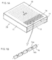
- FIG. 1A is a perspective view showing a color-selecting electrode of one embodiment according to the present invention.
- a mask frame 10 is a rectangular frame and is made of a pair of long frame supports 11, facing each other, fixed to a pair of short frames made of elastic members 12.
- a plurality of slot apertures 14, which are substantially rectangular-shaped slot type electron beam through apertures, are formed by etching.
- FIG. 1A a tension method is employed, the shadow mask 13 is stretched and held between the supports 11 with a tension force applied mainly in the direction illustrated by arrow Y.
- FIG. 1B is an enlarged view of the slot aperture 14.
- the slot aperture 14 is provided with protruding portions 14a and 14b, which are not shown in FIG. 1A.
- the shapes of the slot aperture 14 and the protruding portions 14a and 14b are rectangular, but there is no limitation to this shape.
- the slot aperture 23 and protruding portions 24a and 24b may have round corners.
- protruding portions 26a and 26b of slot apertures 25 may protrude gradually.
- the shape shown in FIG. 7 easily can be realized by an etching method that mainly is used when producing shadow masks. Thus, it is practical.
- the protruding portions will be explained in detail later.
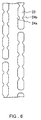
- FIG. 2 is a plan view of a slot type shadow mask of one embodiment.
- FIG. 2B is a partially enlarged view of FIG. 2A.
- the longitudinal direction of the view is a vertical direction of the screen, and the lateral direction of the view is a horizontal direction of the screen.
- the neighboring slot apertures 20 arranged in the longitudinal direction are linked by the bridge 21.
- the protruding portions 22a and 22b are formed. These protruding portions 22a and 22b are protruded from the both ends in the lateral direction of the slot aperture 20.
- the tips of the protruding portions 22a and 22b are facing each other. These pairs of protruding portions 22a and 22b are formed so that the slot apertures 20 are narrowed.
- FIG. 4 is a graph showing the relationship between the longitudinal pitch of the bridge and the doming amount. Fig 4 shows that when the longitudinal pitch of the bridge is increased, it is possible to reduce the doming amount. Furthermore, when the longitudinal pitch of the bridge is increased, the aperture area of the slot aperture also is increased, thus improving the luminance intensity.
- the bridge may be torn due to the stress in the lateral direction accompanying the stress in the longitudinal direction.
- a pair of the protruding portions 22a and 22b solve this problem.
- the protruding portions 22a and 22b it is possible to obtain an effect of substantially cutting scanning lines.
- the protruding portion 22a is separate from the protruding portion 22b, and not only the longitudinal stress but also the lateral stress accompanying the longitudinal stress is not applied, and thus no problems occur in terms of the mechanical strength.
- the protruding portions 22a and 22b do not completely close the slot apertures in the lateral direction. Moreover, as mentioned above, since the stress is not applied to the protruding portions mask as mentioned above. Therefore, for example, the width in the longitudinal direction may be reduced. Also in this case, the lowering of the luminance intensity can be suppressed. That is, according to this embodiment, it is possible to reduce the doming amount of the shadow mask to which a tension force is applied mainly in the longitudinal direction and to suppress the occurrence of moire stripes, while securing the mechanical strength and luminous intensity.
- the bridges and protruding portions are shifted with respect to those of the neighboring slot aperture lines in the lateral direction.
- the shifting amount d in the lateral direction between the bridges in the neighboring lines is small, the length between the bridges arranged neighboring on the same horizontal line is increased. Consequently, it is effective to suppress an occurrence of the moire stripes on the horizontal direction.
- the shifting amount d is in the range from 1/2 to 1/5 with respect to the longitudinal pitch P of the slot aperture 20 (the longitudinal pitch of the bridge 21).
- the longitudinal pitch e of the protruding portions 22a and 22b is 1 mm or less, and the longitudinal pitch P of the slot aperture 20 is in the range from 1.5 to 30 mm. The following is a reason of this.
- ⁇ 1 / (n / 2s - s / a) , wherein " ⁇ ” is a wavelength of moire, "a” denotes a longitudinal pitch of the bridge, “s” denotes an interval between the scanning lines; and “n” denotes a mode order of moire.
- a compromise value of s / a is 9/8 for NTSC, and 11/8 for PAL. Therefore, if the longitudinal pitch a of the bridge is 1 mm or less, even in the case of the plural broadcasting method, it is possible to find a solution for suppressing the occurrence of moire stripes in one shadow mask.
- the longitudinal pitch e of the protruding portions 22a and 22b of the present invention it is preferable that the longitudinal pitch e is 1 mm or less in order to suppress the occurrence of moire stripes.
- the doming amount can be reduced so as to be about 90 ⁇ m or less. Furthermore, it is possible to suppress the vibration of the shadow mask within the practical range, while securing a certain luminance intensity and mechanical strength.
- the vibration can be suppressed to the level of the conventional press mask produced by the press molding.
- the area of a pair of protruding portions 22a and 22b corresponds to 20-120% of the area of one bridge 21.
- the reason why the area is in the above-mentioned range if the area of the protruding portion is too small with respect to the bridge, it is not possible to suppress an occurrence of moire stripes sufficiently. On the contrary, if the area is too large, the luminance intensity is lowered.
- the longitudinal pitch of the protruding portion differs with the part or region in the shadow mask.
- the longitudinal pitch of the protruding portion can be set to be fine in the peripheral portion where moire stripes tend to occur, and on the other hand, the longitudinal pitch of the protruding portion can be set to be longer in the central portion that is hardly affected by moire stripes.
- the longitudinal pitch of the bridge differs with the part or region in the shadow mask.
- the longitudinal pitch P of the bridge as illustrated in FIG. 2B may be about 15 mm in the central portion of the shadow mask and about 5 to 10 mm in the end portion in the lateral direction.
- the peripheral portion in the lateral direction on which the stress to the bridge tends to be concentrated due to the difference in the strength between a region without apertures and a region with apertures it is possible to prevent the shadow mask from being broken by reducing the stress applied to the bridge.
- the longitudinal pitch of the bridge may be about 5 to 10 mm in the central portion, and 10 to 15 mm in the peripheral portion in the lateral direction so as to change the longitudinal pitch gradually.
- the longitudinal pitch of the bridge may be about 5 to 10 mm in the central portion, and 10 to 15 mm in the peripheral portion in the lateral direction so as to change the longitudinal pitch gradually.
- the configuration combining these two structures may be employed.
- the value of the longitudinal pitch of the bridge is gradually increased from the central portion toward the peripheral portion in the lateral direction, and the value is reduced again in the vicinity of the ends of the lateral direction.
- the width of the protruding portion in the longitudinal direction differs with the part or region in the shadow mask.
- the electron beams entering the shadow mask have different incident angles in accordance with the part in the shadow mask.
- the incident angle is acute, the rate at which the electron beam is shielded by the bridges or the protruding portions is increased and the luminance intensity tends to be lowered.
- the electron beams are shielded by the influence of not only the width of the bridge but also the thickness of the shadow mask.
- the protruding portion may be provided only in the peripheral portion without providing the central portion of the shadow mask.
- the central portion of the shadow mask generally rectangular-shaped apertures and bridges are provided; and toward the peripheral portion of the shadow mask, the longitudinal pitch of the bridges is increased gradually and the length of the apertures in the longitudinal direction is increased, as well as the protruding portion is provided in the aperture with the number of the protruding portions increased.
- the longitudinal pitch of the bridge in the peripheral portion of the shadow mask is increased, and thus the strength in the peripheral portion may be insufficient. It is possible to solve this problem by setting the longitudinal width of the bridge to be wide so as to loosen the stress of the bridge.
- the protruding portions 22a and 22b are formed separately and arranged facing each other at their tips, which provides another effect that a geomagnetism characteristic is improved, in addition to the effect mentioned above.
- the cathode ray tube is shielded against the magnetic field from the outside by using a component such as a magnetic shield, or the like, in order that electron beams are not diverted significantly from the regular track.
- the magnetic characteristic generally means that the electron beams are affected by the geomagnetism, thus causing the misalignment of colors.
- the shadow mask capable of selecting colors plays a role of improving the geomagnetic characteristic by shielding the magnetism from the outside.
- the geomagnetism moving to the panel of the cathode ray tube substantially vertically is allowed to flow in the surface direction of the shadow mask, whereby the geomagnetism is prevented from directly affecting the electron beams.
- the geomagnetism In the shadow mask without having a protruding portion in the slot, when the bridge pitch of the shadow mask is large, the geomagnetism easily flows in the vertical direction of the shadow mask. However, since a few bridges are present, the geomagnetism does not easily flow in the horizontal direction. Therefore, particularly in the peripheral portion in which the frame and shadow mask are approaching to each other, the geomagnetism remaining in the shadow mask occasionally floats in the direction of the inside of the tube. Furthermore, the area of the slot aperture is large, the geomagnetism directly passes through the slot aperture so often, whereby the track of electron beams is changed thus to cause the misalignment of colors.
- the protruding portions facing each other play a role of submitting the geomagnetism to each other. Therefore, in addition to the flow of the geomagnetism in the vertical direction, the geomagnetism also flows in not only in the bridge portion but also in the protruding portion. Consequently, the geomagnetism does not float, and furthermore, the effect of picking up the geomagnetism passing through the slot aperture at the protruding portion is exhibited. Therefore, the electron beams are not adversely affected by the geomagnetism. Consequently, it is possible to obtain a cathode ray tube with less misalignment of colors due to the geomagnetism.
Landscapes
- Electrodes For Cathode-Ray Tubes (AREA)
Abstract
Description
Claims (9)
- A cathode ray tube comprisinga mask frame formed in the form of a frame, anda shadow mask made of a flat plate containing a plurality of slot apertures, which is stretched and held onto the mask frame with a tension force applied in the longitudinal direction of the slot apertures,
wherein the shadow mask has bridges linking the slot apertures arranged neighboring in the longitudinal direction, and the slot aperture has protruding portions facing each other and protruding from the both ends of the lateral direction of the slot aperture to the inside of the slot aperture. - The cathode ray tube according to claim 1, wherein the bridges and the protruding portions in the slot aperture line are displaced in the longitudinal direction from the bridges and protruding portions in the neighboring slot aperture line, and the displacing amount is in the range from 1/2 to 1/5 with respect to the longitudinal pitch of the slot aperture.
- The cathode ray tube according to claim 1, wherein the protruding portions are arranged at the longitudinal pitch of 1 mm or less in the slot aperture, and the longitudinal pitch of the bridge is in the range from 1.5 mm to 30 mm.
- The cathode ray tube according to claim 1, wherein the area of a pair of protruding portions arranged neighboring in the lateral direction of the slot aperture is in the range from 20% to 120% with respect to the area of one bridge.
- The cathode ray tube according to claim 1, wherein the longitudinal pitch of the protruding portion differs in different parts of the shadow mask.
- The cathode ray tube according to claim 1, wherein the longitudinal pitch of the bridge differs in different parts of the shadow mask.
- The cathode ray tube according to claim 1, wherein the width of the bridge in the longitudinal direction differs in different parts of the shadow mask.
- The cathode ray tube according to claim 1, wherein the width of the protruding portion in the longitudinal direction differs in different parts of the shadow mask.
- A cathode ray tube comprisinga mask frame formed in the form of a frame, anda shadow mask made of a flat plate containing a plurality of slot apertures, which is stretched and held onto the mask frame with a tension force applied in the longitudinal direction of the slot apertures,
wherein the shadow mask has bridges linking the apertures arranged neighboring in the longitudinal direction, the length of the aperture in the longitudinal direction is longer than the length in the central portion, and the slot aperture in the peripheral portion has protruding portions facing each other and protruding from the both ends of the lateral direction of the slot aperture to the inside of the slot aperture.
Applications Claiming Priority (2)
| Application Number | Priority Date | Filing Date | Title |
|---|---|---|---|
| JP20223099 | 1999-07-15 | ||
| JP20223099 | 1999-07-15 |
Publications (2)
| Publication Number | Publication Date |
|---|---|
| EP1069591A2 true EP1069591A2 (en) | 2001-01-17 |
| EP1069591A3 EP1069591A3 (en) | 2002-02-20 |
Family
ID=16454126
Family Applications (1)
| Application Number | Title | Priority Date | Filing Date |
|---|---|---|---|
| EP00114733A Withdrawn EP1069591A3 (en) | 1999-07-15 | 2000-07-08 | Cathode ray tube |
Country Status (5)
| Country | Link |
|---|---|
| US (1) | US6388370B1 (en) |
| EP (1) | EP1069591A3 (en) |
| KR (1) | KR100399336B1 (en) |
| CN (1) | CN1121704C (en) |
| TW (1) | TW451244B (en) |
Families Citing this family (7)
| Publication number | Priority date | Publication date | Assignee | Title |
|---|---|---|---|---|
| KR100412090B1 (en) * | 1999-11-16 | 2003-12-24 | 삼성에스디아이 주식회사 | Tension mask frame assembly for color CRT |
| KR100334082B1 (en) * | 2000-07-12 | 2002-04-26 | 김순택 | Tension-mask frame assembly for color picture tube |
| KR100334081B1 (en) * | 2000-07-12 | 2002-04-26 | 김순택 | Mask for color picture tube |
| KR100730101B1 (en) * | 2000-12-04 | 2007-06-19 | 삼성에스디아이 주식회사 | Tension mask for flat cathode ray tube |
| KR100728774B1 (en) * | 2001-02-27 | 2007-06-19 | 삼성에스디아이 주식회사 | Color sorting device of cathode ray tube |
| KR100786827B1 (en) * | 2001-06-08 | 2007-12-20 | 삼성에스디아이 주식회사 | Color sorting device of cathode ray tube |
| KR100418040B1 (en) * | 2001-08-08 | 2004-02-11 | 엘지.필립스디스플레이(주) | Color Cathode-ray Tube Containing Improved Bridge Shape of Shadow Mask |
Family Cites Families (11)
| Publication number | Priority date | Publication date | Assignee | Title |
|---|---|---|---|---|
| JP2633303B2 (en) | 1988-06-21 | 1997-07-23 | 松下電子工業株式会社 | Color picture tube |
| US4926089A (en) * | 1988-12-02 | 1990-05-15 | Zenith Electronics Corporation | Tied slit foil shadow mask with false ties |
| JPH0362436A (en) * | 1989-07-31 | 1991-03-18 | Toshiba Corp | Color image receiving tube |
| KR950007681B1 (en) * | 1990-11-22 | 1995-07-14 | 가부시키가이샤 도시바 | Shadow mask, original plate for printing used in the same and manufacturing method thereof |
| JP3053230B2 (en) * | 1991-03-13 | 2000-06-19 | 株式会社東芝 | Color picture tube |
| US5583391A (en) * | 1995-11-15 | 1996-12-10 | Thomson Consumer Electronics, Inc. | Color picture tube shadow mask having improved mask aperture pattern |
| JPH09265916A (en) | 1996-03-29 | 1997-10-07 | Nec Kansai Ltd | Shadow mask and manufacture thereof |
| US6124668A (en) * | 1996-11-05 | 2000-09-26 | Kabushiki Kaisha Toshiba | Color cathode ray tube |
| JPH1116511A (en) * | 1997-06-23 | 1999-01-22 | Nec Kansai Ltd | Shadow mask for color cathode-ray tube and its manufacture |
| KR100267967B1 (en) * | 1998-07-29 | 2000-10-16 | 구자홍 | Flat CRT Shadow Mask |
| KR100354245B1 (en) * | 1999-06-30 | 2002-09-28 | 삼성에스디아이 주식회사 | Tension mask for a CRT |
-
2000
- 2000-07-05 TW TW089113280A patent/TW451244B/en not_active IP Right Cessation
- 2000-07-08 EP EP00114733A patent/EP1069591A3/en not_active Withdrawn
- 2000-07-11 US US09/613,736 patent/US6388370B1/en not_active Expired - Fee Related
- 2000-07-15 KR KR10-2000-0040820A patent/KR100399336B1/en not_active Expired - Fee Related
- 2000-07-17 CN CN00120119A patent/CN1121704C/en not_active Expired - Fee Related
Also Published As
| Publication number | Publication date |
|---|---|
| KR20010029955A (en) | 2001-04-16 |
| TW451244B (en) | 2001-08-21 |
| CN1121704C (en) | 2003-09-17 |
| KR100399336B1 (en) | 2003-09-26 |
| CN1281241A (en) | 2001-01-24 |
| US6388370B1 (en) | 2002-05-14 |
| EP1069591A3 (en) | 2002-02-20 |
Similar Documents
| Publication | Publication Date | Title |
|---|---|---|
| US6472806B1 (en) | Tensioned shadow mask for cathode ray tube including tie bars having dummy bridges | |
| US6710527B2 (en) | Cathode ray tube with slit in dead space of shadow mask | |
| US6388370B1 (en) | Cathode ray tube | |
| US6455991B2 (en) | Cathode ray tube with shadow mask | |
| US6577047B2 (en) | Cathode ray tube | |
| US6566795B2 (en) | Cathode ray tube having apertured shadow mask | |
| JP3835728B2 (en) | Cathode ray tube | |
| EP0982755B1 (en) | Shadow mask for a color cathode ray tube | |
| US6548950B2 (en) | Cathode ray tube having shadow mask with slit between apertures | |
| JP3789267B2 (en) | Cathode ray tube | |
| EP0881659A2 (en) | Color cathode-ray tube | |
| JP3082601B2 (en) | Shadow mask type color cathode ray tube | |
| KR100513246B1 (en) | Color cathode ray tube | |
| JP3878814B2 (en) | Cathode ray tube | |
| US20040217683A1 (en) | Color cathode ray tube and mask assembly for same | |
| JP3981254B2 (en) | Cathode ray tube | |
| JP3856611B2 (en) | Cathode ray tube | |
| JP2006073430A (en) | Color cathode ray tube |
Legal Events
| Date | Code | Title | Description |
|---|---|---|---|
| PUAI | Public reference made under article 153(3) epc to a published international application that has entered the european phase |
Free format text: ORIGINAL CODE: 0009012 |
|
| AK | Designated contracting states |
Kind code of ref document: A2 Designated state(s): DE FR GB IT NL Kind code of ref document: A2 Designated state(s): AT BE CH CY DE DK ES FI FR GB GR IE IT LI LU MC NL PT SE |
|
| AX | Request for extension of the european patent |
Free format text: AL;LT;LV;MK;RO;SI |
|
| RAP1 | Party data changed (applicant data changed or rights of an application transferred) |
Owner name: MATSUSHITA ELECTRIC INDUSTRIAL CO., LTD. |
|
| PUAL | Search report despatched |
Free format text: ORIGINAL CODE: 0009013 |
|
| AK | Designated contracting states |
Kind code of ref document: A3 Designated state(s): AT BE CH CY DE DK ES FI FR GB GR IE IT LI LU MC NL PT SE |
|
| AX | Request for extension of the european patent |
Free format text: AL;LT;LV;MK;RO;SI |
|
| 17P | Request for examination filed |
Effective date: 20020404 |
|
| AKX | Designation fees paid |
Free format text: DE FR GB IT NL |
|
| 17Q | First examination report despatched |
Effective date: 20050401 |
|
| RAP1 | Party data changed (applicant data changed or rights of an application transferred) |
Owner name: PANASONIC CORPORATION |
|
| GRAP | Despatch of communication of intention to grant a patent |
Free format text: ORIGINAL CODE: EPIDOSNIGR1 |
|
| STAA | Information on the status of an ep patent application or granted ep patent |
Free format text: STATUS: THE APPLICATION IS DEEMED TO BE WITHDRAWN |
|
| 18D | Application deemed to be withdrawn |
Effective date: 20090623 |