EP1069492A2 - Security module and method for monitoring de safety of a system - Google Patents
Security module and method for monitoring de safety of a system Download PDFInfo
- Publication number
- EP1069492A2 EP1069492A2 EP00250184A EP00250184A EP1069492A2 EP 1069492 A2 EP1069492 A2 EP 1069492A2 EP 00250184 A EP00250184 A EP 00250184A EP 00250184 A EP00250184 A EP 00250184A EP 1069492 A2 EP1069492 A2 EP 1069492A2
- Authority
- EP
- European Patent Office
- Prior art keywords
- security module
- security
- validation
- system state
- data
- Prior art date
- Legal status (The legal status is an assumption and is not a legal conclusion. Google has not performed a legal analysis and makes no representation as to the accuracy of the status listed.)
- Withdrawn
Links
Images

Classifications
-
- G—PHYSICS
- G06—COMPUTING OR CALCULATING; COUNTING
- G06F—ELECTRIC DIGITAL DATA PROCESSING
- G06F21/00—Security arrangements for protecting computers, components thereof, programs or data against unauthorised activity
- G06F21/50—Monitoring users, programs or devices to maintain the integrity of platforms, e.g. of processors, firmware or operating systems
- G06F21/57—Certifying or maintaining trusted computer platforms, e.g. secure boots or power-downs, version controls, system software checks, secure updates or assessing vulnerabilities
-
- G—PHYSICS
- G07—CHECKING-DEVICES
- G07B—TICKET-ISSUING APPARATUS; FARE-REGISTERING APPARATUS; FRANKING APPARATUS
- G07B17/00—Franking apparatus
- G07B17/00733—Cryptography or similar special procedures in a franking system
-
- G—PHYSICS
- G06—COMPUTING OR CALCULATING; COUNTING
- G06F—ELECTRIC DIGITAL DATA PROCESSING
- G06F2207/00—Indexing scheme relating to methods or arrangements for processing data by operating upon the order or content of the data handled
- G06F2207/72—Indexing scheme relating to groups G06F7/72 - G06F7/729
- G06F2207/7219—Countermeasures against side channel or fault attacks
-
- G—PHYSICS
- G07—CHECKING-DEVICES
- G07B—TICKET-ISSUING APPARATUS; FARE-REGISTERING APPARATUS; FRANKING APPARATUS
- G07B17/00—Franking apparatus
- G07B17/00185—Details internally of apparatus in a franking system, e.g. franking machine at customer or apparatus at post office
- G07B17/00193—Constructional details of apparatus in a franking system
- G07B2017/00233—Housing, e.g. lock or hardened casing
-
- G—PHYSICS
- G07—CHECKING-DEVICES
- G07B—TICKET-ISSUING APPARATUS; FARE-REGISTERING APPARATUS; FRANKING APPARATUS
- G07B17/00—Franking apparatus
- G07B17/00185—Details internally of apparatus in a franking system, e.g. franking machine at customer or apparatus at post office
- G07B17/00193—Constructional details of apparatus in a franking system
- G07B2017/00258—Electronic hardware aspects, e.g. type of circuits used
-
- G—PHYSICS
- G07—CHECKING-DEVICES
- G07B—TICKET-ISSUING APPARATUS; FARE-REGISTERING APPARATUS; FRANKING APPARATUS
- G07B17/00—Franking apparatus
- G07B17/00185—Details internally of apparatus in a franking system, e.g. franking machine at customer or apparatus at post office
- G07B17/00314—Communication within apparatus, personal computer [PC] system, or server, e.g. between printhead and central unit in a franking machine
- G07B2017/00322—Communication between components/modules/parts, e.g. printer, printhead, keyboard, conveyor or central unit
-
- G—PHYSICS
- G07—CHECKING-DEVICES
- G07B—TICKET-ISSUING APPARATUS; FARE-REGISTERING APPARATUS; FRANKING APPARATUS
- G07B17/00—Franking apparatus
- G07B17/00185—Details internally of apparatus in a franking system, e.g. franking machine at customer or apparatus at post office
- G07B17/00314—Communication within apparatus, personal computer [PC] system, or server, e.g. between printhead and central unit in a franking machine
- G07B2017/00338—Error detection or handling
-
- G—PHYSICS
- G07—CHECKING-DEVICES
- G07B—TICKET-ISSUING APPARATUS; FARE-REGISTERING APPARATUS; FRANKING APPARATUS
- G07B17/00—Franking apparatus
- G07B17/00185—Details internally of apparatus in a franking system, e.g. franking machine at customer or apparatus at post office
- G07B17/00362—Calculation or computing within apparatus, e.g. calculation of postage value
- G07B2017/00395—Memory organization
- G07B2017/00403—Memory zones protected from unauthorized reading or writing
-
- G—PHYSICS
- G07—CHECKING-DEVICES
- G07B—TICKET-ISSUING APPARATUS; FARE-REGISTERING APPARATUS; FRANKING APPARATUS
- G07B17/00—Franking apparatus
- G07B17/00733—Cryptography or similar special procedures in a franking system
- G07B2017/00959—Cryptographic modules, e.g. a PC encryption board
- G07B2017/00967—PSD [Postal Security Device] as defined by the USPS [US Postal Service]
Definitions
- the invention relates to a security module for monitoring the System security, in accordance with the preamble of claim 1 specified type and for a method for monitoring the System security in accordance with the preamble of claim 13 specified type.
- a postal security module is especially for use in a franking machine or Mail processing machine or computer with mail processing function suitable.
- Modern franking machines, or other devices for franking from Postgut are using a printer to print the postage stamp on the postal matter, with a control for controlling the printing and the peripheral components of the franking machine, with an accounting unit for billing postal charges that are in non-volatile Stores are kept, and a cryptographic unit Secure postage data.
- the accounting unit and / or the unit for securing the printing of the postage data can be implemented by a security module (EP 789 333 A2).
- the processor of the security module is an OTP, for example (One Time Programmable), which sensitive data, such as cryptographic Key that saves read-out.
- OTP for example (One Time Programmable)
- the invention has for its object a for a security module to achieve maximum security.
- a procedure is to be found which with maximum effort ensures maximum security for allows definable areas and functions of a system, and which universal, d. H. with minimal adjustment effort different electronic systems can be used.
- the method is to be used in franking machines, for example, for the special security requirements apply because the monetary values Billing data must be manipulable.
- the object is with the features of claim 1 for an arrangement and solved with the features of claim 13 for a method.
- a modular structure of the security procedure provides for a two-stage, overlapping check, which basically differentiates between static and dynamic states of the system.
- the data, functions and patterns stored in non-volatile memory areas are suitable for mapping a system status.
- Predetermined sub-areas of the memory can be assigned to specific data processing units and the data stored therein create an image which is characteristic of the status of the system that has been reached.
- Predetermined sub-areas of the memory can be assigned to specific images that are reached one after the other in time.
- the validation of a system status in the event of dynamic changes is based on the overlapping processing of data from at least parts of the test pattern, functional scope or memory area used individually or in combination with one another.
- the overlapping processing consists in mutually exchanging the data supplied by one specific data processing unit and the data supplied by another specific data processing unit and, in one embodiment, a redundant security function on the exchanged data by both data processing units.
- the results of the redundant data processing must be comparable for an unmanipulated and error-free system.
- a security module for a data processing system for example a franking machine, performs its function, for example a billing of the postal charges and / or its cryptographic security.
- the security module has a module processor and a hardware accounting unit.
- the security module is characterized by its own signaling means which, when directly controlled by the processor of the security module, allow a statement to be made about the current status of the security module.
- the signaling of the module status is only activated when the safety module is supplied with system voltage in order to protect an internal battery.
- the processor can also monitor or check the work of the hardware accounting unit. It is not intended to check the settlement itself for accuracy. Can also by one Pattern "comparison of a definable memory area, no backward mapping of the postal registers can be achieved, since the checksums are formed over the data of the entire security-relevant memory area. Because the focus is not on system availability, but on the reliable detection of malfunctions or failures and a suitable reaction on how it is the case with particularly security-sensitive, rather time-uncritical processes.
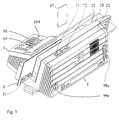
- FIG. 1 is a perspective view of the franking machine from FIG shown at the back.
- the franking machine consists of a meter 1 and a base 2.
- the latter is with a chip card read / write unit 70 equipped, which is arranged behind the guide plate 20 and from the Upper housing edge 22 is accessible.
- a chip card 49 is turned upwards inserted into the slot 72 below.
- the guide plate is in contact with the input data a franking stamp 31 printed.
- the letter feed opening is through a transparent plate 21 and the guide plate 20 laterally limited.
- the module is plugged onto the main board of the meter of the franking machine or another suitable device. It is preferably housed within the meter housing, which is designed as a safety housing.
- the meter housing is advantageously constructed so that the user can still see the status display of the security module from the outside through an opening 109, the opening 109 extending to the user interface 88, 89 of the meter 1.
- the display is controlled directly by the module's internal processor and is therefore not easily manipulated from the outside.
- the display is constantly active in the operating state, so that the application of the system voltage Us + to the processor of the safety module is sufficient to activate the display in order to be able to read the module state.
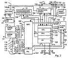
- FIG. 2 shows a block diagram of the postal security module PSM 100 in a preferred variant.
- the negative pole of the battery 134 is grounded and a pin P23 of the contact group 102.
- the positive pole of the battery 134 is connected via line 193 to one input of voltage changeover switch 180 and line 191 carrying system voltage is connected to the other input of voltage changeover switch 180.
- the SL-389 / P is suitable as a battery 134 for a lifespan of up to 3.5 years or the SL-386 / P for a lifespan of up to 6 years with a maximum power consumption by the PSM 100 commercially available circuit type ADM 8693ARN can be used.
- the output of the voltage changeover switch 180 is connected to a voltage monitoring unit 12 and a detection unit 13 via the line 136.
- the voltage monitoring unit 12 and the detection unit 13 are in communication with the pins 1, 2, 4 and 5 of the processor 120 via the lines 135, 164 and 137, 139.
- the output of the voltage switch 180 is also present via the line 136 at the supply input of a first memory SRAM, which becomes a non-volatile memory NVRAM 116 of a first technology due to the existing battery 134.
- the security module is connected to the franking machine via the system bus 115, 117, 118.
- Processor 120 can communicate with a remote data center through the system bus and modem 83.
- the billing is carried out by the ASIC 150.
- the postal accounting data are stored in non-volatile memories of different technologies.
- System voltage is present at the supply input of a second memory NV-RAM 114.
- This second technology preferably comprises a RAM and an EEPROM, the latter automatically taking over the data content in the event of a system power failure.
- the NVRAM 114 of the second technology is connected to the corresponding address and data inputs of the ASIC 150 via an internal address and data bus 112, 113.
- the ASIC 150 contains at least one hardware accounting unit for the calculation of the postal data to be stored.
- An access logic for the ASIC 150 is accommodated in the programmable array logic (PAL) 160.
- the ASIC 150 is controlled by the PAL 160 logic.
- An address and control bus 117, 115 from the main board of meter 1 is connected to corresponding pins of the logic PAL 160 and the PAL 160 generates at least one control signal for the ASIC 150 and one control signal 119 for the program memory FLASH 128.
- the processor 120 works Program stored in the FLASH 128.
- the processor 120, FLASH 28, ASIC 12 and PAL 160 are connected to one another via an internal system bus which contains lines 110, 111, 126, 119 for data, address and control signals.
- the RESET unit 130 is connected via line 131 to pin 3 of the Processor 120 and connected to a pin of the ASIC's 150.
- the Processor 120 and the ASIC 150 are when the Supply voltage through a reset generation in the RESET unit 130 reset.
- the processor 120 internally has a processing unit CPU 121, one Real time clock RTC 122, a RAM unit 124 and an input / output unit 125 on.
- the processor 120 of the security module 100 is via a Internal data bus 126 with a FLASH 128 and with the ASIC 150 connected.
- the FLASH 128 serves as program memory and is included System voltage Us + supplied. For example, it is a 128 Kbyte FLASH memory type AM29F010-45EC.
- the ASIC 150 of the postal security module 100 delivers via an internal module Address bus 110 addresses 0 through 7 to the corresponding address inputs of the FLASH 128.
- the processor 120 of the security module 100 delivers the addresses 8 to 15 to the via an internal address bus 111 corresponding address inputs of the FLASH 128.
- the ASIC 150 of the Security module 100 is located above contact group 101 of the interface with data bus 118, with address bus 117 and control bus 115 the main board of the meter 1 in communication connection.
- the voltage switch 180 gives as the output voltage on the Line 136 for the voltage monitoring unit 12 and memory 116 that of its input voltages further, the greater than the other is. Due to the possibility of depending on the circuit described of the level of the voltages Us + and Ub + automatically with the To feed the larger of the two can during normal operation Battery 134 can be replaced without data loss.
- the RTC real-time clock 122 and the memory RAM 124 are powered by an operating voltage line 138 supplies. This voltage is from the voltage monitoring unit 12 generated.
- the battery of the franking machine feeds outside during idle times the normal operation in the aforementioned manner with the real-time clock 122 Date and / or time registers and / or static RAM (SRAM) 124, which holds security-relevant data.
- the battery voltage drops during battery operation below a certain limit, from the circuit 12 is the feed point for RTC and SRAM with ground connected. This means that the voltage is on the RTC and on the SRAM then at 0V.
- the SRAM 124 e.g. important contains cryptographic keys, is deleted very quickly.
- the registers of the RTC 122 and the current time are also deleted and the current date will be lost.
- the circuit of the voltage monitoring unit 12 is, for example dimensioned so that any drop in battery voltage on the Line 136 below the specified 2.6 V threshold to respond the circuit 12 leads. Simultaneously with the indication of undervoltage the battery, the circuit 12 changes to a self-holding state, in to which it remains even when the voltage is increased afterwards. It delivers also a status signal 164. The next time the module is switched on the processor can query the status of the circuit (status signal) and thus and / or through the evaluation of the content of the deleted The memory suggests that the battery voltage in the meantime has fallen below a certain value. The processor can Reset monitoring circuit 12, i.e. "make sharp. Latter responds to a control signal on line 135.
- the line 136 at the input of the battery observer 12 also supplies a detection unit 13 with operating or battery voltage.
- the processor 120 queries the state of the detection unit 13 via the line 139 or the detection unit 13 is triggered or set by the processor 120 via the line 137. After setting, a static check for connection is carried out. For this purpose, a ground potential is queried via a line 192, which is present at connection P4 of the interface of the postal security module PSM 100 and can only be queried if the security module 100 is properly inserted.
- the ground potential of the negative pole 104 of the battery 134 of the postal security module PSM 100 is connected to the connection P23 of the interface 8 and can thus be queried by the detection unit 13 at the connection P4 of the interface via the line 192.
- Cables are connected to pins 6 and 7 of processor 120, which only form a conductor loop 18 when a security module 100 is plugged in, for example on the main circuit board of meter 1.
- changing signal levels are applied by the processor 120 at very irregular time intervals to the pins 6, 7 and looped back over the loop.
- the processor 120 is equipped with the input / output unit 125, whose connections pins 8, 9 for outputting at least one signal for Signaling the state of the security module 100 serve.
- To the Pins 8 and 9 are I / O ports of the input / output unit 125, to which Internal signal means are connected, for example colored Light emitting diodes LEDs 107, 108. These signal the module status with a security module plugged onto the main board of meter 1 100 through an opening 109 in the meter housing.
- the security modules can assume various states in their life cycle. For example, be detected whether the module is valid contains cryptographic keys. Furthermore, it is also important to distinguish whether the module is working or defective. The exact type and number of module states is dependent on the functions implemented in the Module and depending on the implementation.
- FIG. 3 shows the mechanical structure of the security module in side view.
- the security module is designed as a multi-chip module, i.e. several functional units are on a printed circuit board 106 interconnected.
- the security module 100 is with a hard potting compound 105 potted, the battery 134 of the security module 100 exchangeable outside the sealing compound 105 on a printed circuit board 106 is arranged.
- it is with a potting material 105 potted that the signaling means 107, 108 from the potting material protrudes at a first point and that the circuit board 106 with the inserted battery 134 protrudes to the side of a second location.
- the Circuit board 106 also has battery contact terminals 103 and 104 for the connection of the poles of the battery 134, preferably on the Component side above the circuit board 106. It is provided that to connect the PSM 100 postal security module to the Motherboard of meter 1, the contact groups 101 and 102 below the Printed circuit board 106 (conductor track side) of the security module 100 are.
- the ASIC 150 user circuit is higher than the first Contact group 101 - in a manner not shown - with the system bus one Control device 1 in communication connection and the second Contact group 102 serves to supply safety module 100 with the system voltage.
- the security module is on the main board inserted, then it is preferably within the meter housing arranged so that the signal means 107, 108 near a Opening 109 is or protrudes into this.
- the meter case is so advantageously constructed so that the user can view the status of the Security module can still see from the outside.
- the two LEDs 107 and 108 of the signaling means are via two output signals of the I / O ports on pins 8, 9 of processor 120 are controlled. Both LEDs are housed in a common component housing (Bicolor LED), which is why the dimensions or diameter the opening can remain relatively small and of the order of magnitude Signal means is. In principle, three different colors can be displayed (red, green, orange), depending on which the LED's individually or simultaneously can be controlled.
- the LEDs are also used to differentiate the status individually or together flashing, if necessary controlled alternately flashing, see above that a variety of different conditions can be distinguished, in which at least one of the LEDs is activated.
- FIG. 4 is a top view of the postal security module shown.
- the potting compound 105 surrounds a first part in a cuboid shape the circuit board 106, while a second part of the circuit board 106 for the replaceable battery 134 remains free of potting compound.
- the battery contact terminals 103 and 104 are here from the battery covered.
- a green lit LED 107 signals an OK state 220, but a lit LED 108 signals an error state 230 as a result of an at least static self-test.
- the result of such a self-test known per se cannot be falsified because of the direct signaling via the LEDs 107, 108.
- the ongoing check in dynamic operation would determine the error and signal it as state 240 with orange LEDs. Booting is required after switching off / on, otherwise no other operation can be carried out.
- state 260 The case that the installation of a key was forgotten during manufacture is signaled as state 260, for example with a flashing green LED 107.
- state 250 The case that a long time watchdog timer has expired is also signaled as status 250 by a flashing red LED.
- the long time watchdog timer has expired if the data center has not been contacted for a long time, for example to reload a credit.
- State 250 is also reached when the safety module has been disconnected from the meter. Additional status displays for the states 270, 280, 290 are optionally provided for various other tests.
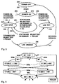
- FIG. 6 shows an illustration of the testing of the integrity of the system for statically and dynamically changeable states.
- a turned off System in state 200 goes through the transition after switching on Start 201 in state 210, in which of the security modules a static self-test is carried out as soon as the operating voltage is present.
- transition 202 where the self-test is OK If the result is correct, the state 220 LED turns green achieved brilliant. Starting from the latter state is a if necessary repeated static self-test and a dynamic self-test feasible.
- Such a transition 203 or 206 either leads back to status 220 LED green when OK or to status 240 LED orange in the event of an error.
- transition 211 the switched-on device has a static Executes self-test
- transition 204 in the event of an error Condition 230 LED red.
- a static self-test can be carried out on demand in the event of an error via transition 205 to status 230 LED red to lead.
- LED green can not shown further transitions 207, 208, 209 to the further states 270 (with flashing orange LED's signaling), 280 (with red glowing / orange blinking LEDs indicate) and 290 (with green glowing / orange blinking LED's).
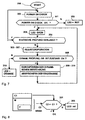
- FIG. 7 shows a flow diagram for checking the integrity of the system.
- the microprocessor CPU 121 is programmed by a corresponding program stored in the flash 128 to carry out the aforementioned self-tests, a power-on self-test being carried out in a first step 300 after the start 299 and then a question being asked in step 301 as to whether the power on Self-test has given an OK. If this is the case, in step 302 the green LED 107 is controlled by the microprocessor CPU 121 via an I / O port 125 to light up. Otherwise, in step 303, the red LED 108 is controlled by the microprocessor CPU 121 via an I / O port 125 to light up.
- Step 302 branches to query 304, in which it is checked whether a further static check is required. If this is the case, the method branches back to step 300. Otherwise, at least one register operation is carried out in steps 305-307 and then a branch is made to query 308, in which it is checked whether the actual state is valid or correct. In the course of the register operation or afterwards, a dynamic check is carried out. If this is not proceeding properly or is faulty, then a branch is made from query step 308 to step 315 and both the green LED 107 and the red LED 108 are controlled by the microprocessor CPU 121 via an I / O port 125 in a luminous manner. This gives the overall impression that the LEDs are orange.
- step 308 if the actual state is satisfactory, a dynamic calculation is carried out in steps 309-314 and the results are subsequently stored. From the last step, branching back to script 302. This results in a two-stage check on demand. For the dynamic calculation, it is sufficient for the microprocessor CPU 121 to test only partial functions at different times using the same or a different calculation method, whereby both calculation methods must of course lead to the same check result OK or DEFECT or ERROR.
- the safety-relevant functions F In a system with the memory area M and a large number of functions F, a safety-relevant sub-area M and F protected against malfunctions and failures.
- the safety-relevant functions F as far as they are not exclusively in the memory area M work in such a way that they unambiguous check marks (Pattern) of their (successful) mode of operation in the system in the memory area M depict.
- the security method now basically differentiates between two different system states: the static one, in which the content of the memory area M not changed and the dynamic, in which a change in the memory area M he follows.
- the security method according to the invention provides for overlapping processing with validation of the system state that is now taking place.
- the memory area M Redundant design and contains at least two figures M1 corresponding in type and scope and - in the static state - also corresponding in content and M2 in the form of data stored in sub memory areas M 1 'and M 2 '.
- the address management of sub-areas M 1 and M 2 to M x of the area M made such that at least always the last current and validated state - e.g. B. M1 - is available in the memory area M 1 '.
- B. M2 - In the memory area M 2 ', it is provided as a first option, in particular if external influence on the system by third parties can be ruled out, that the currently changing process from the functional scope F - e.g. B. F1 - Execute several times in order to be formed by meanwhile Pattern "Cx over the data in the area M 2 as well as the comparison of the temporarily saved pattern results, the new state M2 to take over as validated and the state M1 consequently to be overwritten by subsequent changes.
- the security process has its own intelligence to use at least some functions from F in order to execute a volatile mirror image of M2 in the first step and then the associated mirror pattern Cx for comparison with the Original ".
- a saved pattern C1 was generated and validated for the first time by a system initialization.
- the microprocessor 120 controls the LED signaling glowing red (font 303).
- Steps 305 and 306 of the flowchart for checking the integrity of the system shown in FIG. 7 can be divided into sub-steps.
- the memory area M is redundant as memory area M. executed, both of which correspond in type and scope and - in the static state - also in terms of the data content, which is illustrated by sub-step 305a. Otherwise there is an error, ie the figures M1 and M1 do not correspond.
- both memory areas M1 ', M1 treated separately, each by a safety function F1 ', F1 is executed, which changes the data content, so that the images M2 and M2 arise.
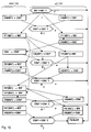
- FIG. 10 shows an overlapping processing in combination with overlapping checksums and / or with overlapping operations shown.
- the dynamic self-test can be performed according to the Security requirements carried out in various variations become.
- the microprocessor (120) is programmed to program is an overlapping one with dynamic changes in the system state Perform processing of at least part of the used Range of functions or the test pattern used. Subsequently validation always takes place. It is intended to be overlapping Processing of at least parts of the test pattern used, the Functional range or memory area in combination with each other for subsequent validation.
- the data processing system in particular a Franking machine
- the security module can also be another Have design that allows it, for example, on the The main board of a personal computer can be plugged in as a PC franking device controls a commercially available printer.
Landscapes
- Engineering & Computer Science (AREA)
- Theoretical Computer Science (AREA)
- Physics & Mathematics (AREA)
- General Physics & Mathematics (AREA)
- Computer Hardware Design (AREA)
- General Engineering & Computer Science (AREA)
- Computer Security & Cryptography (AREA)
- Software Systems (AREA)
- Storage Device Security (AREA)
- Alarm Systems (AREA)
- Devices For Checking Fares Or Tickets At Control Points (AREA)
Abstract
Die Erfindung betrifft ein Sicherheitsmodul zur Überwachung der Systemsicherheit, mit einem Mikroprozessor (120), der mit weiteren Funktionseinheiten verschaltet ist, wobei der Mikroprozessor (120) zur überlappenden Verarbeitung mit zwischenzeitlich stattfindender Validierung des Systemzustands programmiert ist und zur Signalisierung des Modulzustandes ein Signalmittel (107, 108) ansteuert. <IMAGE>The invention relates to a security module for monitoring system security, comprising a microprocessor (120) which is connected to further functional units, the microprocessor (120) being programmed for overlapping processing with meanwhile validation of the system status and a signaling means (107 , 108) controls. <IMAGE>
Description
Die Erfindung betrifft ein Sicherheitsmodul zur Überwachung der
Systemsicherheit, gemäß der im Oberbegriff des Anspruchs 1
angegebenen Art und für ein Verfahren zur Überwachung der
Systemsicherheit gemäß der im Oberbegriff des Anspruchs 13
angegebenen Art. Ein solcher postalischer Sicherheitsmodul ist
insbesondere für den Einsatz in einer Frankiermaschine bzw.
Postbearbeitungsmaschine oder Computer mit Postbearbeitungsfunktion
geeignet.The invention relates to a security module for monitoring the
System security, in accordance with the preamble of
Es sind vielfältige Sicherungsmaßnahmen zum Schutz gegen Ausfälle bzw. Störungen als auch zur Bereitstellung einer 100%-tigen Verfügbarkeit von intelligenten elektronischen Systemen bekannt. Beispielsweise werden Parallelrechnersysteme für extrem hohe Sicherheitsanforderungen (Flugverkehr etc.) eingesetzt, eher für low-level Anwendungen werden z. B. gespeicherte Ergebnisse redundant ausgeführt konzipiert, um so die Möglichkeit des Erkennens einer Fehlfunktion bzw. eines Ausfalls sowie ggf. auch die Möglichkeit zur Korrektur zu schaffen. Vielfach sind die einzelnen Sicherungsmaßnahmen sehr unterschiedlicher Natur (z. B. Kombinationen von Hard- und Software) und müssen dem jeweiligen Erfordernis der (evtl. auch nur partiell erforderlichen) Sicherheit eines Systems angepaßt werden, was zu entsprechend vielen dedizierten Einzellösungen führt, die durch ihren individuellen Charakter hohe Design- und - unter Umständen - auch Realisierungskosten verursachen.There are various security measures to protect against failures or disruptions as well as to provide a 100% Known availability of intelligent electronic systems. For example, parallel computer systems for extremely high Security requirements (air traffic etc.) used, more for low-level Applications are e.g. B. saved results redundant designed to be able to recognize one Malfunction or failure and possibly also the possibility of Create correction. The individual security measures are often very different in nature (e.g. combinations of hardware and Software) and must meet the respective requirements of (possibly only partially required) security of a system can be adjusted, leading to according to many dedicated individual solutions, which through their individual character high design and - under certain circumstances - also Realization costs cause.
Es ist bereits aus EP 417 447 B1 bekannt, in elektronischen Datenverarbeitungsanlagen besondere Module einzusetzen und mit Mitteln zum Schutz vor einem Einbruch in ihre Elektronik auszustatten. Solche Module werden nachfolgend Sicherheitsmodule genannt.It is already known from EP 417 447 B1, in electronic data processing systems to use special modules and with means for Provide protection against a break-in in their electronics. Such modules are called security modules below.
Moderne Frankiermaschinen, oder andere Einrichtungen zum Frankieren von Postgut, sind mit einem Drucker zum Drucken des Postwertstempels auf das Postgut, mit einer Steuerung zum Steuern des Druckens und der peripheren Komponenten der Frankiermaschine, mit einer Abrecheneinheit zum Abrechnen von Postgebühren, die in nichtflüchtigen Speichern gehalten werden, und einer Einheit zum kryptografischen Absichern der Postgebührendaten ausgestattet. Die Abrecheneinheit und/oder die Einheit zum Absichern des Druckens der Postgebührendaten kann von einem Sicherheitsmodul realisiert werden (EP 789 333 A2). Der Prozessor des Sicherheitsmoduls ist beispielsweise ein OTP (One Time Programmable), welcher sensible Daten, wie kryptografische Schlüssel, auslesesicher speichert. Eine Kapselung durch ein Sicherheitsgehäuse bietet einen weiteren Schutz.Modern franking machines, or other devices for franking from Postgut, are using a printer to print the postage stamp on the postal matter, with a control for controlling the printing and the peripheral components of the franking machine, with an accounting unit for billing postal charges that are in non-volatile Stores are kept, and a cryptographic unit Secure postage data. The accounting unit and / or the unit for securing the printing of the postage data can be implemented by a security module (EP 789 333 A2). The processor of the security module is an OTP, for example (One Time Programmable), which sensitive data, such as cryptographic Key that saves read-out. An encapsulation by a Security housing provides further protection.
Weitere Maßnahmen zum Schutz eines Sicherheitsmoduls vor einem
Angriff auf die in ihm gespeicherten Daten wurden auch in den nicht
vorveröffentlichten deutschen Anmeldungen 198 16 572.2 8 mit dem Titel:
![]()
![]()
Der Erfindung liegt die Aufgabe zugrunde, für ein Sicherheitsmodul eine maximale Sicherheit zu erzielen. Es soll ein Verfahren gefunden werden, welches mit minimalen Aufwänden eine maximale Sicherheit für definierbare Bereiche und Funktionen eines Systems ermöglicht, und welches universell, d. h. mit nur minimalem Anpassungsaufwand, auf unterschiedlichste elektronische Systeme angewendet werden kann. Das Verfahren soll beispielsweise in Frankiermaschinen Anwendung finden, für die besondere Sicherheitsforderungen gelten, da die geldwerten Abrechnungsdaten unmanipulierbar sein müssen.The invention has for its object a for a security module to achieve maximum security. A procedure is to be found which with maximum effort ensures maximum security for allows definable areas and functions of a system, and which universal, d. H. with minimal adjustment effort different electronic systems can be used. The The method is to be used in franking machines, for example, for the special security requirements apply because the monetary values Billing data must be manipulable.
Die Aufgabe wird mit den Merkmalen des Anspruchs 1 für eine Anordnung
und mit den Merkmalen des Anspruchs 13 für ein Verfahren gelöst.The object is with the features of
Durch eine zeitlich wiederholend überprüfte Integrität des Systems wird
die Sicherheit des elektronischen Systems gewährleistet. Ein modularer
Aufbau des Sicherheitsverfahrens sieht eine zweistufige, überlappende
Prüfung vor, die grundsätzlich zwischen statischen und dynamischen
Zuständen des Systems unterscheidet. Die in Speicherbereichen nichtflüchtig
gespeicherte Daten, Funktionen und Pattern sind geeignet einen
Systemzustand abzubilden. Vorbestimmte Subbereiche des Speichers
können bestimmten Datenverarbeitungseinheiten zugeordnet werden und
die darin gespeicherten Daten schaffen eine Abbildung, welche für den
erreichten Zustand des Systems kennzeichnend ist. Vorbestimmte
Subbereiche des Speichers können bestimmten Abbildungen zugeordnet
werden, die zeitlich nacheinander erreicht werden.
Die Validierung eines Systemzustands bei dynamischen Änderungen beruht
auf der überlappenden Verarbeitung von Daten aus mindestens
Teilen des verwendeten Prüfpattern, Funktionsumfanges oder Speicherbereiches
einzeln oder in Kombination miteinander. Die überlappende
Verarbeitung besteht in einem gegenseitigem Vertauschen der von der
einen bestimmten Datenverarbeitungseinheit gelieferten Daten und der
von einer anderen bestimmten Datenverarbeitungseinheit gelieferten
Daten und in einer Ausführung jeweils einer redundanten Sicherheitsfunktion
auf die vertauschten Daten durch beide Datenverarbeitungseinheiten.
Die Ergebnisse der redundanten Datenverarbeitung müssen bei
einem unmanipulierten und fehlerfrei arbeitenden System vergleichbar
sein.
Ein Sicherheitsmodul für eine Datenverarbeitungsanlage, beispielsweise
eine Frankiermaschine, nimmt deren Funktion, beispielsweise einer Abrechnung
der Postgebühren und/oder deren kryptografische Absicherung
war. Das Sicherheitsmodul hat einen Modulprozessor und eine Hardware-Abrecheneinheit.
Das Sicherheitsmodul ist erfindungsgemäß durch eigene
Signalmittel gekennzeichnet, die bei direkter Ansteuerung vom Prozessor
des Sicherheitsmoduls eine Aussage über den aktuellen Zustand des
Sicherheitsmoduls gestatten. Die Signalisierung des Modulzustandes wird
nur bei Versorgung des Sicherheitsmoduls mit Systemspannung aktiviert,
um eine interne Batterie zu schonen. Der Prozessor kann auch die Arbeit
der Hardware-Abrecheneinheit überwachen oder überprüfen. Es ist nicht
beabsichtigt, die Abrechnung selbst auf Richtigkeit nachzuprüfen. Auch
kann durch einen
The validation of a system status in the event of dynamic changes is based on the overlapping processing of data from at least parts of the test pattern, functional scope or memory area used individually or in combination with one another. The overlapping processing consists in mutually exchanging the data supplied by one specific data processing unit and the data supplied by another specific data processing unit and, in one embodiment, a redundant security function on the exchanged data by both data processing units. The results of the redundant data processing must be comparable for an unmanipulated and error-free system.
A security module for a data processing system, for example a franking machine, performs its function, for example a billing of the postal charges and / or its cryptographic security. The security module has a module processor and a hardware accounting unit. According to the invention, the security module is characterized by its own signaling means which, when directly controlled by the processor of the security module, allow a statement to be made about the current status of the security module. The signaling of the module status is only activated when the safety module is supplied with system voltage in order to protect an internal battery. The processor can also monitor or check the work of the hardware accounting unit. It is not intended to check the settlement itself for accuracy. Can also by one
Vorteilhafte Weiterbildungen der Erfindung sind in den Unteransprüchen gekennzeichnet bzw. werden nachstehend zusammen mit der Beschreibung der bevorzugten Ausführung der Erfindung anhand der Figuren näher dargestellt. Es zeigen:
Figur 1,- Perspektivische Ansicht der Frankiermaschine von hinten,
Figur 2,- Blockschaltbild des Sicherheitsmoduls,
Figur 3,- Seitenansicht des Sicherheitsmoduls,
- Figur 4,
- Draufsicht auf das Sicherheitsmodul,
- Figur 5,
- Tabelle für Statussignalisierung,
- Figur 6,
- Darstellung der Prüfung der Integrität des Systems für statische und dynamisch änderbare Zustände,
Figur 7,- Flußdiagramm für die Prüfung der Integrität des Systems,
Figur 8,- Darstellung der statischen Prüfung,
- Figur 9 und 10,
- Darstellung der überlappenden Verarbeitung.
- Figure 1,
- Perspective view of the franking machine from behind,
- Figure 2,
- Block diagram of the safety module,
- Figure 3,
- Side view of the security module,
- Figure 4,
- Top view of the security module,
- Figure 5,
- Status signaling table,
- Figure 6,
- Representation of checking the integrity of the system for static and dynamically changeable states,
- Figure 7,
- Flow chart for checking the integrity of the system,
- Figure 8,
- Representation of the static test,
- Figures 9 and 10,
- Representation of the overlapping processing.
In der Figur 1 ist eine perspektivische Ansicht der Frankiermaschine von
hinten dargestellt. Die Frankiermaschine besteht aus einem Meter 1 und
einer Base 2. Letztere ist mit einer Chipkarten-Schreib/ Leseeinheit 70
ausgestattet, die hinter der Führungsplatte 20 angeordnet und von der
Gehäuseoberkante 22 zugänglich ist. Nach dem Einschalten der Frankiermaschine
mittels dem Schalter 71 wird eine Chipkarte 49 von oben nach
unten in den Einsteckschlitz 72 eingesteckt. Ein zugeführter auf der Kante
stehender Brief 3, der mit seiner zu bedruckenden Oberfläche an der
Führungsplatte anliegt, wird dann entsprechend der Eingabedaten mit
einem Frankierstempel 31 bedruckt. Die Briefzuführöffnung wird durch
eine Klarsichtplatte 21 und die Führungsplatte 20 seitlich begrenzt.FIG. 1 is a perspective view of the franking machine from FIG
shown at the back. The franking machine consists of a
Das Modul wird auf die Hauptplatine des Meters der Frankiermaschine
oder eines anderen geeigneten Gerätes gesteckt. Es ist vorzugsweise
innerhalb des Metergehäuses untergebracht, welches als Sicherheitsgehäuse
ausgebildet ist. Das Metergehäuse ist dabei vorteilhaft so
konstruiert, daß der Benutzer die Statusanzeige des Sicherheitsmoduls
trotzdem von außen durch eine Öffnung 109 sehen kann, wobei sich die
Öffnung 109 zur Bedienoberfläche 88, 89 des Meters 1 erstreckt.
Die Anzeige wird direkt vom modulinternen Prozessor gesteuert und ist so
von außen nicht ohne weiteres manipulierbar. Die Anzeige ist im
Betriebszustand ständig aktiv, so daß das Anlegen der Systemspannung
Us+ an den Prozessor des Sicherheitsmoduls ausreicht, die Anzeige zu
aktivieren, um den Modulzustand ablesen zu können.The module is plugged onto the main board of the meter of the franking machine or another suitable device. It is preferably housed within the meter housing, which is designed as a safety housing. The meter housing is advantageously constructed so that the user can still see the status display of the security module from the outside through an
The display is controlled directly by the module's internal processor and is therefore not easily manipulated from the outside. The display is constantly active in the operating state, so that the application of the system voltage Us + to the processor of the safety module is sufficient to activate the display in order to be able to read the module state.
Die Figur 2 zeigt ein Blockschaltbild des postalischen Sicherheitsmoduls
PSM 100 in einer bevorzugten Variante. Der negative Pol der Batterie 134
ist auf Masse und einen Pin P23 der Kontaktgruppe 102 gelegt. Der
positive Pol der Batterie 134 ist über die Leitung 193 mit dem einen
Eingang des Spannungsumschalters 180 und die Systemspannung
führende Leitung 191 ist mit dem anderen Eingang des Spannungsumschalters
180 verbunden. Als Batterie 134 eignet sich der Typ SL-389/P
für eine Lebensdauer bis zu 3,5 Jahren oder der Typ SL-386/P für
eine Lebensdauer bis zu 6 Jahren bei einem maximalen Stromverbrauch
durch das PSM 100. Als Spannungsumschalter 180 kann ein handelsüblicher
Schaltkreis vom Typ ADM 8693ARN eingesetzt werden. Der
Ausgang des Spannungsumschalters 180 liegt über die Leitung 136 an
einer Spannungsüberwachungseinheit 12 und einer Detektionseinheit 13
an. Die Spannungsüberwachungseinheit 12 und die Detektionseinheit 13
stehen mit den Pins 1, 2, 4 und 5 des Prozessors 120 über die Leitungen
135, 164 und 137, 139 in Kommunikationsverbindung. Der Ausgang des
Spannungsumschalters 180 liegt über die Leitung 136 außerdem am
Versorgungseingang eines ersten Speichers SRAM an, der durch die
vorhandene Batterie 134 zum nichtflüchtigen Speicher NVRAM 116 einer
ersten Technologie wird.
Das Sicherheitsmodul steht mit der Frankiermaschine über den
Systembus 115, 117, 118 in Verbindung. Der Prozessor 120 kann über
den Systembus und ein Modem 83 in Kommunikationsverbindung mit
einer entfernten Datenzentrale eintreten. Die Abrechnung wird vom ASIC
150 vollzogen. Die postalischen Abrechnungsdaten werden in
nichtflüchtigen Speichern unterschiedlicher Technologie gespeichert.
Am Versorgungseingang eines zweiten Speichers NV-RAM 114 liegt
Systemspannung an. Hierbei handelt es sich um einen nichtflüchtigen
Speicher NVRAM einer zweiten Technologie, (SHADOW-RAM). Diese
zweiten Technologie umfaßt vorzugsweise ein RAM und ein EEPROM,
wobei letzteres die Dateninhalte bei Systemspannungsausfall automatisch
übernimmt. Der NVRAM 114 der zweiten Technologie ist mit den
entsprechenden Adress- und Dateneingängen des ASIC's 150 über einen
internen Adreß- und Datenbus 112, 113 verbunden.FIG. 2 shows a block diagram of the postal
The security module is connected to the franking machine via the
System voltage is present at the supply input of a second memory NV-
Der ASIC 150 enthält mindestens eine Hardware-Abrecheneinheit für die
Berechnung der zu speichernden postalischen Daten. In der
Programmable Array Logic (PAL) 160 ist eine Zugriffslogik für den ASIC
150 untergebracht. Der ASIC 150 wird durch die Logik PAL 160 gesteuert.
Ein Adreß- und Steuerbus 117, 115 von der Hauptplatine des Meters 1 ist
an entsprechenden Pins der Logik PAL 160 angeschlossen und die PAL
160 erzeugt mindestens ein Steuersignal für das ASIC 150 und ein
Steuersignal 119 für den Programmspeicher FLASH 128. Der Prozessor
120 arbeitet ein Programm ab, das im FLASH 128 gespeichert ist. Der
Prozessor 120, FLASH 28, ASIC 12 und PAL 160 sind über einen
modulinternen Systembus miteinander verbunden, der Leitungen
110, 111, 126, 119 für Daten-, Adreß- und Steuersignale enthält. The
An address and
Die RESET-Einheit 130 ist über die Leitung 131 mit dem Pin 3 des
Prozessors 120 und mit einem Pin des ASIC's 150 verbunden. Der
Prozessor 120 und das ASIC 150 werden bei Absinken der
Versorgungsspannung durch eine Resetgenerierung in der RESET-Einheit
130 zurückgesetzt.The
Der Prozessor 120 weist intern eine Verarbeitungseinheit CPU 121, eine
Echtzeituhr RTC 122 eine RAM-Einheit 124 und eine Ein/Ausgabe-Einheit
125 auf. Der Prozessor 120 des Sicherheitsmoduls 100 ist über einen
modul-internen Datenbus 126 mit einem FLASH 128 und mit dem ASIC
150 verbunden. Der FLASH 128 dient als Programmspeicher und wird mit
Systemspannung Us+ versorgt. Er ist beispielsweise ein 128 Kbyte-FLASH-Speicher
vom Typ AM29F010-45EC. Der ASIC 150 des
postalischen Sicherheitsmoduls 100 liefert über einen modulinternen
Adreßbus 110 die Adressen 0 bis 7 an die entsprechenden Adreßeingänge
des FLASH 128. Der Prozessor 120 des Sicherheitsmoduls 100
liefert über einen internen Adreßbus 111 die Adressen 8 bis 15 an die
entsprechenden Adresseingänge des FLASH 128. Der ASIC 150 des
Sicherheitsmoduls 100 steht über die Kontaktgruppe 101 des Interfaces
mit dem Datenbus 118, mit dem Adreßbus 117 und dem Steuerbus 115
der Hauptplatine des Meters 1 in Kommunikationsverbindung.The
Der Spannungsumschalter 180 gibt als Ausgangsspannung auf der
Leitung 136 für die Spannungsüberwachungseinheit 12 und Speicher 116
diejenige seiner Eingangsspannungen weiter, die größer als die andere
ist. Durch die Möglichkeit, die beschriebene Schaltung in Abhängigkeit
von der Höhe der Spannungen Us+ und Ub+ automatisch mit der
größeren von beiden zu speisen, kann während des Normalbetriebs die
Batterie 134 ohne Datenverlust gewechselt werden. Die Echtzeituhr RTC
122 und der Speicher RAM 124 werden von einer Betriebsspannung über
die Leitung 138 versorgt. Diese Spannung wird von der Spannungsüberwachungseinheit
12 erzeugt. The
Die Batterie der Frankiermaschine speist in den Ruhezeiten außerhalb
des Normalbetriebes in vorerwähnter Weise die Echtzeituhr 122 mit
Datums und/oder Uhrzeitregistern und/oder den statischen RAM (SRAM)
124, der sicherheitsrelevante Daten hält. Sinkt die Spannung der Batterie
während des Batteriebetriebs unter eine bestimmte Grenze, so wird von
der Schaltung 12 der Speisepunkt für RTC und SRAM mit Masse
verbunden. Das heißt, die Spannung an der RTC und am SRAM liegt
dann bei 0V. Das führt dazu, daß der SRAM 124, der z.B. wichtige
kryptografische Schlüssel enthält, sehr schnell gelöscht wird. Gleichzeitig
werden auch die Register der RTC 122 gelöscht und die aktuelle Uhrzeit
und das aktuelle Datum gehen verloren. Durch diese Aktion wird verhindert,
daß ein möglicher Angreifer durch Manipulation der Batteriespannung
die frankiermaschineninterne Uhr 122 anhält, ohne daß sicherheitsrelevante
Daten verloren gehen. Somit wird verhindert, daß er Sicherheitsmaßnahmen,
wie beispielsweise Sleeping Mode (EP 660 268 A2)
oder Long Time Watchdog (wird anhand der Fig.5 noch erläutert) umgeht.The battery of the franking machine feeds outside during idle times
the normal operation in the aforementioned manner with the real-
Die Schaltung der Spannungsüberwachungseinheit 12 ist beispielsweise
so dimensioniert, daß jegliches Absinken der Batteriespannung auf der
Leitung 136 unter die spezifizierte Schwelle von 2,6 V zum Ansprechen
der Schaltung 12 führt. Gleichzeitig mit der Indikation der Unterspannung
der Batterie wechselt die Schaltung 12 in einen Selbsthaltezustand, in
dem sie auch bei nachträglicher Erhöhung der Spannung bleibt. Sie liefert
außerdem ein Statussignal 164. Beim nächsten Einschalten des Moduls
kann der Prozessor den Zustand der Schaltung abfragen (Statussignal)
und damit und/oder über die Auswertung der Inhalte des gelöschten
Speichers darauf schließen, daß die Batteriespannung zwischenzeitlich
einen bestimmten Wert unterschritten hat. Der Prozessor kann die
Überwachungsschaltung 12 zurücksetzen, d.h. "scharf" machen. Letztere
reagiert auf ein Steuersignal auf der Leitung 135.The circuit of the
Die Leitung 136 am Eingang des Batterieobservers 12 versorgt zugleich
eine Detektions-Einheit 13 mit Betriebs- oder Batteriespannung. Vom
Prozessor 120 wird der Zustand der Detektions-Einheit 13 über die
Leitung 139 abgefragt oder die Detektions-Einheit 13 wird vom Prozessor
120 über die Leitung 137 ausgelöst bzw. gesetzt. Nach dem Setzen wird
eine statische Prüfung auf Anschluß durchgeführt. Dazu wird über eine
Leitung 192 Massepotential abgefragt, welches am Anschluß P4 des
Interfaces des postalischen Sicherheitsmoduls PSM 100 anliegt und nur
abfragbar ist, wenn der Sicherheitsmodul 100 ordnungsgemäß gesteckt
ist. Bei gesteckten Sicherheitsmodul 100 wird Massepotential des
negativen Pols 104 der Batterie 134 des postalischen Sicherheitsmoduls
PSM 100 auf den Anschluß P23 des Interfaces 8 gelegt und ist somit am
Anschluß P4 des Interfaces über die Leitung 192 von der Detektions-Einheit
13 abfragbar.
An den Pins 6 und 7 des Prozessors 120 sind Leitungen angeschlossen,
welche nur bei einem, beispielsweise an die Hauptplatine des Meters 1,
gesteckten Sicherheitsmodul 100 eine Leiterschleife 18 bilden. Zur
dynamischen Prüfung des Zustandes des Angeschlossenseins des
postalischen Sicherheitsmoduls PSM 100 an der Hauptplatine des Meters
1 werden vom Prozessor 120 wechselnde Signalpegel in ganz
unregelmäßigen Zeitabständen an die Pin's 6, 7 angelegt und über die
Schleife zurückgeschleift.The
Cables are connected to
Der Prozessor 120 ist mit der Ein/Ausgabe-Einheit 125 ausgestattet,
deren Anschlüsse Pin's 8, 9 zur Ausgabe mindestens eines Signals zur
Signalisierung des Zustandes des Sicherheitsmoduls 100 dienen. An den
Pin's 8 und 9 liegen I/O-Ports der Ein/Ausgabe-Einheit 125, an welchen
modulinterne Signalmittel angeschlossen sind, beispielsweise farbige
Lichtemitterdioden LED's 107, 108. Diese signalisieren den Modulzustand
bei einem auf die Hauptplatine des Meters 1 gesteckten Sicherheitsmoduls
100 durch eine Öffnung 109 im Metergehäuse. Die Sicherheitsmodule
können in ihrem Lebenszyklus verschiedene Zustände einnehmen.
So muß z.B. detektiert werden, ob das Modul gültige
kryptografische Schlüssel enthält. Weiterhin ist es auch wichtig zu
unterscheiden, ob das Modul funktioniert oder defekt ist. Die genaue Art
und Anzahl der Modulzustände ist von den realisierten Funktionen im
Modul und von der Implementierung abhängig. The
Die Figur 3 zeigt zeigt den mechanischen Aufbau des Sicherheitsmoduls
in Seitenansicht. Das Sicherheitsmodul ist als Multi-Chip-Modul ausgebildet,
d.h. mehrere Funktionseinheiten sind auf einer Leiterplatte 106
verschaltet. Das Sicherheitsmodul 100 ist mit einer harten Vergußmasse
105 vergossen, wobei die Batterie 134 des Sicherheitsmoduls 100
außerhalb der Vergußmasse 105 auf einer Leiterplatte 106 auswechselbar
angeordnet ist. Beispielsweise ist es so mit einem Vergußmaterial
105 vergossen, daß das Signalmittel 107, 108 aus dem Vergußmaterial
an einer ersten Stelle herausragt und daß die Leiterplatte 106 mit der
gesteckten Batterie 134 seitlich einer zweiten Stelle herausragt. Die
Leiterplatte 106 hat außerdem Batteriekontaktklemmen 103 und 104 für
den Anschluß der Pole der Batterie 134, vorzugsweise auf der
Bestückungsseite oberhalb der Leiterplatte 106. Es ist vorgesehen, daß
zum Anstecken des postalischen Sicherheitsmoduls PSM 100 auf die
Hauptplatine des Meters 1 die Kontaktgruppen 101 und 102 unterhalb der
Leiterplatte 106 (Leiterbahnseite) des Sicherheitsmoduls 100 angeordnet
sind. Der Anwenderschaltkreis ASIC 150 steht über die erste
Kontaktgruppe 101 - in nicht gezeigter Weise - mit dem Systembus einer
Steuereinrichtung 1 in Kommunikationsverbindung und die zweite
Kontaktgruppe 102 dient der Versorgung des Sicherheitsmoduls 100 mit
der Systemspannung. Wird das Sicherheitsmodul auf die Hauptplatine
gesteckt, dann ist es vorzugsweise innerhalb des Metergehäuses
dergestalt angeordnet, so daß das Signalmittel 107, 108 nahe einer
Öffnung 109 ist oder in diese hineinragt. Das Metergehäuse ist damit
vorteilhaft so konstruiert, daß der Benutzer die Statusanzeige des
Sicherheitsmoduls trotzdem von außen sehen kann. Die beiden Leuchtdioden
107 und 108 des Signalmittels werden über zwei Ausgangssignale
der I/O-Ports an den Pin 8, 9 des Prozessors 120 gesteuert. Beide
Leuchtdioden sind in einem gemeinsamen Bauelementegehäuse untergebracht
(Bicolorleuchtdiode), weshalb die Abmaße bzw. der Durchmesser
der Öffnung relativ klein bleiben kann und in der Größenordnung des
Signalmittels liegt. Prinzipiell sind drei unterschiedliche Farben darstellbar
(rot, grün, orange), jenachdem die LED's einzeln oder gleichzeitig
angesteuert werden. Zur Zustandsunterscheidung werden die LED's auch
einzeln oder zusammen blinkend ggf. abwechselnd blinkend gesteuert, so
daß ein Vielzahl verschiedener Zustande unterschieden werden können,
in welchem mindestens eine der LED's aktiviert wird.FIG. 3 shows the mechanical structure of the security module
in side view. The security module is designed as a multi-chip module,
i.e. several functional units are on a printed
In der Figur 4 ist eine Draufsicht auf das postalische Sicherheitsmodul
dargestellt. Die Vergußmasse 105 umgibt quaderförmig einen ersten Teil
der Leiterplatte 106, während ein zweiter Teil der Leiterplatte 106 für die
auswechselbar angeordnete Batterie 134 von Vergußmasse frei bleibt.
Die Batteriekontaktklemmen 103 und 104 werden hier von der Batterie
verdeckt.FIG. 4 is a top view of the postal security module
shown. The
Gemäß einer in der Figur 5 gezeigten - sich selbst erläuternden - Tabelle
für Statussignalisierung geht eine Vielzahl möglicher Zustandsanzeigen
hervor. Eine grün leuchtende LED 107 signalisiert einen OK-Zustand 220,
aber eine leuchtende LED 108 signalisiert einen Fehler-Zustand 230 im
Ergebnis eines mindestens statischen Selbsttestes. Das Ergebnis eines
solchen an sich bekannten Selbsttestes kann wegen der direkten
Signalisierung über die LED's 107, 108 nicht verfälscht werden.
Beispielsweise für den Fall, daß zwischenzeitlich die im Sicherheitsmodul
gespeicherten Schlüssel verloren gingen, würde die laufende Überprüfung
im dynamischen Betrieb den Fehler feststellen und als den Zustand 240
mit orange leuchtenden LED's signalisieren. Nach einem Aus/Einschalten
ist ein Booten erforderlich, da anderenfalls keine andere Operation mehr
ausgeführt werden kann. Der Fall, daß bei der Herstel-lung die Installation
eines Schlüssels vergessen wurde, wird als Zustand 260 beispielsweise
mit einer grün blinkenden LED 107 signalisiert. Auch der Fall, daß ein long
time watchdog-Timer abgelaufen ist, wird als Zu-stand 250 durch eine rot
blinkende LED signalisiert. Der long time watchdog-Timer ist abgelaufen,
wenn lange Zeit die Datenzentrale nicht mehr kontaktiert wurde,
beispielsweise um ein Guthaben nachzuladen. Der Zustand 250 wird
ebenfalls erreicht, wenn das Sicherheitsmodul vom Meter getrennt wurde.
Weitere Zustandsanzeigen für die Zustände 270, 280, 290 sind optional
für verschiedene weitere Prüfungen vorgesehen. According to a - self-explanatory - table for status signaling shown in FIG. 5, a large number of possible status displays are shown. A green lit LED 107 signals an
For example, in the event that the keys stored in the security module were lost in the meantime, the ongoing check in dynamic operation would determine the error and signal it as
Additional status displays for the
Die Figur 6 zeigt eine Darstellung der Prüfung der Integrität des Systems
für statisch und dynamisch änderbare Zustände. Ein ausgeschaltetes
System im Zustand 200 geht nach dem Einschalten über die Transition
Start 201 in den Zustand 210 über, in welchem vom Sicherheitsmodule
ein statischer Selbsttest durchgeführt wird sobald die Betriebsspannung
anliegt. Bei der Transition 202, bei der der Selbsttest ein OK bei
ordnungsgemäßem Ergebnis ergibt, wird der Zustand 220 LED grün
leuchtend erreicht. Ausgehend von letzterem Zustand ist bei Bedarf ein
wiederholter statischer Selbsttest und ein dynamischer Selbsttest
durchführbar. Eine solche Transition 203 oder 206 führt entweder zurück
auf den Zustand 220 LED grün bei OK oder auf den Zustand 240 LED
orange bei einem Fehler. Letzterer ist durch einen Recover-Versuch evtl.
durch Ausschalten (Transition 211) und Wiedereinschalten des Gerätes
(Transition 201) behebbar. Statische Fehler sind aber nicht behebbar. Von
Zustand 210, in welchem das eingeschaltete Gerät einen statischen
Selbsttest ausführt, existiert bei einem Fehler eine Transition 204 zum
Zustand 230 LED rot. Zu jeder Zeit, wenn sich das Gerät im Zustand 220
LED grün befindet, kann ein on demand ausgeführter statischer Selbsttest
bei einem Fehler über eine Transition 205 zum Zustand 230 LED rot
führen. Ausgehend vom Zustand 220 LED grün können nicht gezeigte
weitere Transitionen 207, 208, 209 zu den weiteren Zuständen 270 (mit
orange blinkenden LED's signalisiert), 280 (mit rot leuchtend/orange
blinkenden LED's signalisiert) und 290 (mit grün leuchtend/orange
blinkenden LED's signalisiert) führen.FIG. 6 shows an illustration of the testing of the integrity of the system
for statically and dynamically changeable states. A turned off
System in
Die Figur 7 zeigt ein Flußdiagramm für die Prüfung der Integrität des
Systems. Der Mikroprozessor CPU 121 ist durch ein entsprechendes im
Flash 128 gespeichertes Programm programmiert, solche vorgenannten
Selbsttests auszuführen, wobei nach dem Start 299, in einem ersten
Schritt 300 ein Power on-Selbsttest durchgeführt und dann im Schritt 301
gefragt wird, ob der Power on-Selbsttest ein OK ergeben hat. Ist das der
Fall, so wird im Schritt 302 die grüne LED 107 vom Mikroprozessor CPU
121 über ein I/O-Port 125 leuchtend gesteuert. Anderenfalls wird im
Schritt 303 die rote LED 108 vom Mikroprozessor CPU 121 über ein I/O-Port
125 leuchtend gesteuert.
Vom Schritt 302 wird auf die Abfrage 304 verzweigt, in welcher geprüft
wird, ob eine weitere statische Prüfung verlangt wird. Ist das der Fall, so
wird zum Schritt 300 zurückverzweigt. Anderenfalls wird in den Schritten
305 - 307 mindestens eine Registeroperation durchgeführt und dann wird
auf die Abfrage 308 verzweigt, in welcher geprüft wird, ob der Ist-Zustand
gültig bzw. ordnungsgemäß ist. Im Verlauf der Registeroperation oder
anschließend, wird eine dynamische Prüfung durchgeführt. Wenn diese
nicht ordnungsgemäß verläuft oder fehlerbehaftet ist, dann wird vom
Abfrageschritt 308 zum Schritt 315 verzweigt und beide, die grüne LED
107 und die rote LED 108, werden vom Mikroprozessor CPU 121 über ein
I/O-Port 125 leuchtend gesteuert. Somit ergibt sich der Gesamteindruck,
daß die LED's orange leuchten. Anschließend an den Abfrageschritt 308
wird bei einem zufriedenstellenden Ist-Zustand in den Schritten 309-314
eine dynamische Berechnung und nachfolgend ein Abspeichern der
Ergebnisse durchgeführt. Vom letzten Schritt wird zum Schrift 302 zurückverzweigt.
Dadurch ergibt sich on demand eine zweistufige Prüfung. Für
die dynamische Berechnung ist es ausreichend, wenn zur Prüfung vom
Mikroprozessor CPU 121 nur Teilfunktionen zeitlich versetzt auf dem
gleichen oder auf einem anderen Rechenweg nachvollzogen werden, wobei
selbstverständlich beide Rechenwege zum selben Überprüfungsergebnis
OK oder DEFECT bzw. ERROR führen müssen.FIG. 7 shows a flow diagram for checking the integrity of the system. The
Step 302 branches to query 304, in which it is checked whether a further static check is required. If this is the case, the method branches back to
In einem System mit dem Speicherbereich M und einer Vielzahl an
Funktionen F soll ein in der Größe bzw. im Umfang definierbarer
sicherheitsrelevanter Teilbereich M![]()
Interessant ist nun die Betrachtung der zweiten, dynamischen
Systemstufe, in der sich der Speicherinhalt M
Eine weitere Möglichkeit besteht darin, daß das Sicherheitsverfahren über
eigene Intelligenz verfügt, um mindestens einige Funktionen aus F![]()
It is now interesting to consider the second, dynamic system level in which the memory content M
Another possibility is that the security process has its own intelligence to use at least some functions from F
Anhand eines in der Figur 8 gezeigten Beispiels soll das Verfahren im
einzelnen erläutert werden. Ein gespeichertes Pattern C1 wurde erstmalig
durch eine Systeminitialisierung generiert und validiert. Durch eine mathematische
Einweg-Funktion wird ein Pattern C2 des Speicherbereichs M
Anhand der Figur 9, welche eine Darstellung der überlappenden
Verarbeitung zeigt, wird der dynamische Selbsttest erläutert. Die Schritte
305 und 306 des in der Figur 7 gezeigten Flußdiagramms für die Prüfung
der Integrität des Systems können in Subschritte aufgeteilt ablaufen. Der
Speicherbereich M![]()
Anderenfalls liegt ein Fehler vor, d.h. die Abbildungen M1![]()
Otherwise there is an error, ie the figures M1
In der Figur 10 wird eine überlappende Verarbeitung in Kombination mit überlappenden Prüfsummen und/oder mit überlappenden Operationen gezeigt. Der dynamische Selbsttest kann entsprechend den Sicherheitsanforderungen in unterschiedlichsten Variationen ausgeführt werden. Es ist vorgesehen, daß der Mikroprozessor (120) programmiert ist, bei dynamischen Änderungen des Systemzustands eine überlappende Verarbeitung durchzuführen, von mindestens einem Teil des verwendeten Funktionsumfanges oder des verwendeten Prüfpattern. Anschließend erfolgt immer die Validierung. Es ist vorgesehen, die überlappende Verarbeitung von mindestens Teilen des verwendeten Prüfpattern, des Funktionsumfanges oder Speicherbereiches in Kombination miteinander zur anschließenden Validierung durchzuführen.FIG. 10 shows an overlapping processing in combination with overlapping checksums and / or with overlapping operations shown. The dynamic self-test can be performed according to the Security requirements carried out in various variations become. The microprocessor (120) is programmed to program is an overlapping one with dynamic changes in the system state Perform processing of at least part of the used Range of functions or the test pattern used. Subsequently validation always takes place. It is intended to be overlapping Processing of at least parts of the test pattern used, the Functional range or memory area in combination with each other for subsequent validation.
Es wird deutlich, daß sich allein durch die Ausgestaltung der Umgebung
und Art des Sicherheitsverfahrens beliebig hohe Sicherheitsanforderungen
realisieren lassen, die auf demselben Grundgedanken fußende
unterschiedliche Ausgestaltungen zulassen. So ist beispielsweise auch
durch entsprechend viele Unterbereiche Mx
Es ist weiterhin vorteilhaft, daß zur Ausführung des Sicherheitsverfahrens
der bereits vorhandene Systemprozessor genutzt wird, was jedoch nicht
ausschließt, daß auch das gesamte Sicherheitsverfahren in
It is also advantageous that the already existing system processor is used to carry out the security procedure, but this does not exclude that the entire security procedure in
Bemerkenswert ist, daß es das beschriebene Verfahren ermöglicht, ohne Rückschlüsse auf den vorhandenen Datenbestand oder die vorhandene Funktionalität eines elektronischen Systems zu liefern, die Validierung in punkto System-Integrität frei definierbarer Systembereiche und - funktionen lückenlos durchzuführen.It is remarkable that the described method enables it without Conclusions about the existing database or the existing one Functionality of an electronic system to deliver validation in in terms of system integrity of freely definable system areas and - to perform functions seamlessly.
Erfindungsgemäß ist die Datenverarbeitungsanlage, insbesondere eine Frankiermaschine, jedoch kann das Sicherheitsmodul auch eine andere Bauform aufweisen, die es ermöglicht, daß es beispielsweise auf die Hauptplatine eines Personalcomputers gesteckt werden kann, der als PC-Frankierer einen handelsüblichen Drucker ansteuert.According to the invention, the data processing system, in particular a Franking machine, however, the security module can also be another Have design that allows it, for example, on the The main board of a personal computer can be plugged in as a PC franking device controls a commercially available printer.
Die Erfindung ist nicht auf die vorliegenden Ausführungsform beschränkt, da offensichtlich weitere andere Anordnungen bzw. Ausführungen der Erfindung entwickelt bzw. eingesetzt werden können, die - vom gleichen Grundgedanken der Erfindung ausgehend - von den anliegenden Schutzansprüchen umfaßt werden.The invention is not limited to the present embodiment, since obviously other arrangements or designs of the Invention can be developed or used, the - of the same Basic ideas of the invention starting from the adjacent Protection claims are included.
Claims (20)
Applications Claiming Priority (2)
| Application Number | Priority Date | Filing Date | Title |
|---|---|---|---|
| DE19928061A DE19928061C2 (en) | 1999-06-15 | 1999-06-15 | Security module to monitor system security and procedures |
| DE19928061 | 1999-06-15 |
Publications (2)
| Publication Number | Publication Date |
|---|---|
| EP1069492A2 true EP1069492A2 (en) | 2001-01-17 |
| EP1069492A3 EP1069492A3 (en) | 2006-04-19 |
Family
ID=7911801
Family Applications (1)
| Application Number | Title | Priority Date | Filing Date |
|---|---|---|---|
| EP00250184A Withdrawn EP1069492A3 (en) | 1999-06-15 | 2000-06-09 | Security module and method for monitoring de safety of a system |
Country Status (3)
| Country | Link |
|---|---|
| US (1) | US6351220B1 (en) |
| EP (1) | EP1069492A3 (en) |
| DE (1) | DE19928061C2 (en) |
Families Citing this family (4)
| Publication number | Priority date | Publication date | Assignee | Title |
|---|---|---|---|---|
| DE102004027517B4 (en) * | 2004-06-03 | 2007-05-10 | Francotyp-Postalia Gmbh | Arrangement and method for controlling a thermal transfer print head |
| US8245068B2 (en) * | 2006-10-27 | 2012-08-14 | Freescale Semiconductor, Inc. | Power supply monitoring method and system |
| US9009860B2 (en) * | 2011-11-03 | 2015-04-14 | Cram Worldwide, Llc | Tamper resistance extension via tamper sensing material housing integration |
| US9720716B2 (en) * | 2013-03-12 | 2017-08-01 | Intel Corporation | Layered virtual machine integrity monitoring |
Citations (7)
| Publication number | Priority date | Publication date | Assignee | Title |
|---|---|---|---|---|
| EP0789333A2 (en) | 1996-01-31 | 1997-08-13 | Francotyp-Postalia Aktiengesellschaft & Co. | Franking machine |
| EP0417447B1 (en) | 1989-09-12 | 1997-10-29 | International Business Machines Corporation | Data protection by detection of intrusion into electronic assemblies |
| DE29905219U1 (en) | 1999-03-12 | 1999-06-17 | Francotyp-Postalia AG & Co., 16547 Birkenwerder | Security module with status signaling |
| DE19816571A1 (en) | 1998-04-07 | 1999-10-14 | Francotyp Postalia Gmbh | Access protection for security modules |
| DE19816572A1 (en) | 1998-04-07 | 1999-10-14 | Francotyp Postalia Gmbh | Security module to prevent manipulation of data |
| DE19912780A1 (en) | 1999-03-12 | 2000-09-14 | Francotyp Postalia Gmbh | Arrangement for a security module |
| DE19912781A1 (en) | 1999-03-12 | 2000-11-23 | Francotyp Postalia Gmbh | Method for protecting a security module and arrangement for carrying out the method |
Family Cites Families (11)
| Publication number | Priority date | Publication date | Assignee | Title |
|---|---|---|---|---|
| US4253158A (en) * | 1979-03-28 | 1981-02-24 | Pitney Bowes Inc. | System for securing postage printing transactions |
| US4812994A (en) * | 1985-08-06 | 1989-03-14 | Pitney Bowes Inc. | Postage meter locking system |
| DE59308113D1 (en) | 1993-03-11 | 1998-03-12 | Francotyp Postalia Gmbh | Procedure for storing security-relevant data |
| DE4315732C1 (en) * | 1993-05-11 | 1994-06-01 | Siemens Nixdorf Inf Syst | Personal computer software integrity booting and testing - conducting power-on self-test in ROM-BIOS, loading partition, loading boot sector of operating system partition, starting operating system and kernel, and using one=way hash function for cryptographic key and testing |
| DE4344476A1 (en) * | 1993-12-21 | 1995-06-22 | Francotyp Postalia Gmbh | Process for improving the security of franking machines |
| US5572429A (en) * | 1994-12-05 | 1996-11-05 | Hunter; Kevin D. | System for recording the initialization and re-initialization of an electronic postage meter |
| DE19534530A1 (en) * | 1995-09-08 | 1997-03-13 | Francotyp Postalia Gmbh | Process for securing data and program code of an electronic franking machine |
| US6169804B1 (en) * | 1996-11-21 | 2001-01-02 | Pitney Bowes Inc. | Method for verifying the expected postage security device and its status |
| US5946672A (en) * | 1997-06-12 | 1999-08-31 | Pitney Bowes Inc. | Electronic postage meter system having enhanced clock security |
| US6023690A (en) * | 1997-06-12 | 2000-02-08 | Pitney Bowes Inc. | Method and apparatus for securely resetting a real time clock in a postage meter |
| US6044364A (en) * | 1997-12-08 | 2000-03-28 | Pitney Bowes Inc. | Method and apparatus for ensuring for the correct accounting of postage dispensed by a postage meter |
-
1999
- 1999-06-15 DE DE19928061A patent/DE19928061C2/en not_active Expired - Fee Related
-
2000
- 2000-06-09 EP EP00250184A patent/EP1069492A3/en not_active Withdrawn
- 2000-06-14 US US09/594,002 patent/US6351220B1/en not_active Expired - Fee Related
Patent Citations (7)
| Publication number | Priority date | Publication date | Assignee | Title |
|---|---|---|---|---|
| EP0417447B1 (en) | 1989-09-12 | 1997-10-29 | International Business Machines Corporation | Data protection by detection of intrusion into electronic assemblies |
| EP0789333A2 (en) | 1996-01-31 | 1997-08-13 | Francotyp-Postalia Aktiengesellschaft & Co. | Franking machine |
| DE19816571A1 (en) | 1998-04-07 | 1999-10-14 | Francotyp Postalia Gmbh | Access protection for security modules |
| DE19816572A1 (en) | 1998-04-07 | 1999-10-14 | Francotyp Postalia Gmbh | Security module to prevent manipulation of data |
| DE29905219U1 (en) | 1999-03-12 | 1999-06-17 | Francotyp-Postalia AG & Co., 16547 Birkenwerder | Security module with status signaling |
| DE19912780A1 (en) | 1999-03-12 | 2000-09-14 | Francotyp Postalia Gmbh | Arrangement for a security module |
| DE19912781A1 (en) | 1999-03-12 | 2000-11-23 | Francotyp Postalia Gmbh | Method for protecting a security module and arrangement for carrying out the method |
Also Published As
| Publication number | Publication date |
|---|---|
| DE19928061C2 (en) | 2003-08-28 |
| EP1069492A3 (en) | 2006-04-19 |
| US6351220B1 (en) | 2002-02-26 |
| DE19928061A1 (en) | 2000-12-28 |
Similar Documents
| Publication | Publication Date | Title |
|---|---|---|
| EP1035517B1 (en) | Method for the protection of a security module and arrangement for implementing said method | |
| EP1035516B1 (en) | Arrangement for a security module | |
| EP0762337A2 (en) | Method and device for enhancing manipulation-proof of critical data | |
| DE4445053C2 (en) | Interface circuit internal to the franking machine | |
| EP0762335B1 (en) | Method for changing data charged in memory cells of an electronic franking machine | |
| EP1035518B1 (en) | Arrangement for the protection of a security module | |
| DE10137505B4 (en) | Arrangement and method for changing the functionality of a security module | |
| DE19928057B4 (en) | Security module and method for securing the postal registers from manipulation | |
| EP0854425B1 (en) | Device and method for increasing data security with circular buffer | |
| EP1035513B1 (en) | Security module with status signalization | |
| DE19928061C2 (en) | Security module to monitor system security and procedures | |
| EP1209631B1 (en) | Power supply arrangement for a security part of an apparatus | |
| DE19534530A1 (en) | Process for securing data and program code of an electronic franking machine | |
| EP0560714B1 (en) | Postage meter | |
| DE20112350U1 (en) | Arrangement for protecting a security module | |
| DE10213009A1 (en) | Electronic testing procedure for memory modules, such as dual in-line modules (DIMMs), requires making electronic comparison between number of modules and number of module identifiers | |
| DE3875269T2 (en) | Coupling device for non-volatile memories in an electronic machine and their use in franking machines. | |
| DE60125854T2 (en) | Removable electronic device for increasing the functionality of a main processor and control method thereto | |
| DE69425546T2 (en) | Dynamically programmable time counting | |
| DE3040532C2 (en) | Reloadable electronic franking machine | |
| DE19534529C2 (en) | Process for increasing the security against manipulation of critical data | |
| EP1213817A2 (en) | Method for the determination of a need to exchange a component and device for carrying out the method | |
| DE19534527C2 (en) | Process for increasing the security against manipulation of critical data | |
| EP0645710A2 (en) | Method of testing for functionality of a technically signal-unsecure memory for at least in two channels stored information data and arrangement for implementing the method | |
| DE102024114169B3 (en) | Device for executing instructions in a zone of a vehicle, circuit for the device, vehicle comprising the device |
Legal Events
| Date | Code | Title | Description |
|---|---|---|---|
| PUAI | Public reference made under article 153(3) epc to a published international application that has entered the european phase |
Free format text: ORIGINAL CODE: 0009012 |
|
| AK | Designated contracting states |
Kind code of ref document: A2 Designated state(s): AT BE CH CY DE DK ES FI FR GB GR IE IT LI LU MC NL PT SE |
|
| AX | Request for extension of the european patent |
Free format text: AL;LT;LV;MK;RO;SI |
|
| RAP1 | Party data changed (applicant data changed or rights of an application transferred) |
Owner name: FRANCOTYP-POSTALIA AG & CO. KG |
|
| RAP1 | Party data changed (applicant data changed or rights of an application transferred) |
Owner name: FRANCOTYP-POSTALIA GMBH |
|
| PUAL | Search report despatched |
Free format text: ORIGINAL CODE: 0009013 |
|
| AK | Designated contracting states |
Kind code of ref document: A3 Designated state(s): AT BE CH CY DE DK ES FI FR GB GR IE IT LI LU MC NL PT SE |
|
| AX | Request for extension of the european patent |
Extension state: AL LT LV MK RO SI |
|
| RIC1 | Information provided on ipc code assigned before grant |
Ipc: G07B 17/00 20060101AFI20060301BHEP |
|
| 17P | Request for examination filed |
Effective date: 20060505 |
|
| 17Q | First examination report despatched |
Effective date: 20061113 |
|
| AKX | Designation fees paid |
Designated state(s): CH DE FR GB IT LI |
|
| STAA | Information on the status of an ep patent application or granted ep patent |
Free format text: STATUS: THE APPLICATION IS DEEMED TO BE WITHDRAWN |
|
| 18D | Application deemed to be withdrawn |
Effective date: 20120103 |