EP1069429A2 - X-ray image radiographing method and radiographing apparatus - Google Patents
X-ray image radiographing method and radiographing apparatus Download PDFInfo
- Publication number
- EP1069429A2 EP1069429A2 EP00114791A EP00114791A EP1069429A2 EP 1069429 A2 EP1069429 A2 EP 1069429A2 EP 00114791 A EP00114791 A EP 00114791A EP 00114791 A EP00114791 A EP 00114791A EP 1069429 A2 EP1069429 A2 EP 1069429A2
- Authority
- EP
- European Patent Office
- Prior art keywords
- ray
- image
- ray image
- image radiographing
- size
- Prior art date
- Legal status (The legal status is an assumption and is not a legal conclusion. Google has not performed a legal analysis and makes no representation as to the accuracy of the status listed.)
- Granted
Links
Images


Classifications
-
- A—HUMAN NECESSITIES
- A61—MEDICAL OR VETERINARY SCIENCE; HYGIENE
- A61B—DIAGNOSIS; SURGERY; IDENTIFICATION
- A61B6/00—Apparatus or devices for radiation diagnosis; Apparatus or devices for radiation diagnosis combined with radiation therapy equipment
- A61B6/48—Diagnostic techniques
- A61B6/484—Diagnostic techniques involving phase contrast X-ray imaging
-
- G—PHYSICS
- G01—MEASURING; TESTING
- G01N—INVESTIGATING OR ANALYSING MATERIALS BY DETERMINING THEIR CHEMICAL OR PHYSICAL PROPERTIES
- G01N23/00—Investigating or analysing materials by the use of wave or particle radiation, e.g. X-rays or neutrons, not covered by groups G01N3/00 – G01N17/00, G01N21/00 or G01N22/00
- G01N23/02—Investigating or analysing materials by the use of wave or particle radiation, e.g. X-rays or neutrons, not covered by groups G01N3/00 – G01N17/00, G01N21/00 or G01N22/00 by transmitting the radiation through the material
- G01N23/04—Investigating or analysing materials by the use of wave or particle radiation, e.g. X-rays or neutrons, not covered by groups G01N3/00 – G01N17/00, G01N21/00 or G01N22/00 by transmitting the radiation through the material and forming images of the material
- G01N23/041—Phase-contrast imaging, e.g. using grating interferometers
-
- A—HUMAN NECESSITIES
- A61—MEDICAL OR VETERINARY SCIENCE; HYGIENE
- A61B—DIAGNOSIS; SURGERY; IDENTIFICATION
- A61B6/00—Apparatus or devices for radiation diagnosis; Apparatus or devices for radiation diagnosis combined with radiation therapy equipment
- A61B6/40—Arrangements for generating radiation specially adapted for radiation diagnosis
- A61B6/4021—Arrangements for generating radiation specially adapted for radiation diagnosis involving movement of the focal spot
-
- A—HUMAN NECESSITIES
- A61—MEDICAL OR VETERINARY SCIENCE; HYGIENE
- A61B—DIAGNOSIS; SURGERY; IDENTIFICATION
- A61B6/00—Apparatus or devices for radiation diagnosis; Apparatus or devices for radiation diagnosis combined with radiation therapy equipment
- A61B6/40—Arrangements for generating radiation specially adapted for radiation diagnosis
- A61B6/4064—Arrangements for generating radiation specially adapted for radiation diagnosis specially adapted for producing a particular type of beam
- A61B6/4092—Arrangements for generating radiation specially adapted for radiation diagnosis specially adapted for producing a particular type of beam for producing synchrotron radiation
-
- A—HUMAN NECESSITIES
- A61—MEDICAL OR VETERINARY SCIENCE; HYGIENE
- A61B—DIAGNOSIS; SURGERY; IDENTIFICATION
- A61B6/00—Apparatus or devices for radiation diagnosis; Apparatus or devices for radiation diagnosis combined with radiation therapy equipment
- A61B6/50—Apparatus or devices for radiation diagnosis; Apparatus or devices for radiation diagnosis combined with radiation therapy equipment specially adapted for specific body parts; specially adapted for specific clinical applications
- A61B6/502—Apparatus or devices for radiation diagnosis; Apparatus or devices for radiation diagnosis combined with radiation therapy equipment specially adapted for specific body parts; specially adapted for specific clinical applications for diagnosis of breast, i.e. mammography
-
- G—PHYSICS
- G21—NUCLEAR PHYSICS; NUCLEAR ENGINEERING
- G21K—HANDLING OF PARTICLES OR IONISING RADIATION NOT OTHERWISE PROVIDED FOR; IRRADIATION DEVICES; GAMMA RAY OR X-RAY MICROSCOPES
- G21K2207/00—Particular details of imaging devices or methods using ionizing electromagnetic radiation such as X-rays or gamma rays
- G21K2207/005—Methods and devices obtaining contrast from non-absorbing interaction of the radiation with matter, e.g. phase contrast
Definitions
- the present invention relates to a X-ray radiographing method and a radiographing apparatus capable of being applicable to medical service and non-destructive test, in particular, to a X-ray radiographing method and a radiographing apparatus capable of depicting a boundary of a radiographed object with high contrast.
- an X-ray image can be formed by detecting the two dimensional distribution of the transmission amount of X-ray.
- X-ray is an electromagnetic wave
- X-ray has a nature of a wave. Accordingly, when X-ray transmits an object, diffraction or refraction is caused by deviation in phase and the diffraction or the refraction can be detected as an image.
- a X-ray image formation by utilizing the above nature has not been conducted.
- a method of radiographing a X-ray image of an object with high contrast by utilizing the above nature has been suggested.
- the X-ray image obtained by this method is called a phase contrast X-ray image.
- the contrast at a boundary region of the object may be enhanced, the detected ability of a X-ray image can be increased. Therefore, the method is desired to be applied to medical service using X-ray and non-destructive test for industry.
- phase contrast X-ray radiographing apparatus according to a interference method employing a Mach Zehnder type interferometer by using a synchrotron radiation X-ray has been suggested. Further, in "Medical Applications of Synchrotron Radiation” (M. Ando and C. Uyamam eds., Springer-Verlag Tokyo, 1998), a lot of technical reports to apply the phase contrast X-ray image by using the synchrotron radiation X-ray to medical service are described.
- This apparatus can obtain a strong monochromic X-ray in the form of a spatial coherent parallel light.
- the form that X-ray is "spatial coherent” or “lateral spatial coherent” provides the characteristics that the X-ray has coherence as wave.
- the synchrotron radiation X-ray generating apparatus is set up recently as "SPring-8" in Akou-districts Hyogo-prefecture and also in the physical construction science research institute in a higher energy accelerator research organization.
- SPring-8 the synchrotron radiation X-ray generating apparatus
- these apparatus are too huge constructions to be utilized by private medical facilities and needs a huge amount of construction cost. Therefore, these apparatus have hardly been utilized by a private facility for medical purpose or other inspections.
- Wilkins reported a method of obtaining a phase contrast X-ray image from a fish or a small animal by using a micro focus X-ray source and the radiographing method for the X-ray image is described in the patent publication WO 96/31098.
- Wilkins describes a X-ray image radiographing apparatus and a radiographing method by using the apparatus in which a X-ray source having a size of focal spot deemed as a spot light source such as a size of focal spot not larger than 20 ⁇ m is used in order to obtain X-ray having a high lateral spatial coherence and the distance between an object to be radiographed and a X-ray detector is set more than 0.3 m.
- the present invention has been conceived in view of the above problem and an object of the invention is to provide a X-ray image radiographing method capable of obtaining a widely practically usable phase contrast X-ray image and a radiographing apparatus using the method in contrast with a conventional X-ray imaging method and an apparatus for the conventional method which is lack of practical use in a working spot for medical service or non-destructive test.
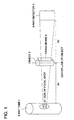
- Fig. 1 The X-ray image radiographing method and the apparatus for the method in the present invention is illustrated conceptually as shown in Fig. 1.
- fixing means 4 to determine the positions of a X-ray tube 1 and an object to be photographed and to fix them at the respective positions and a X-ray detector 3.
- the distance between the X-ray tube 1 and the object 2 is represented as R1 and the distance between the object and the X-ray detector 3 is represented as R2.
- the fixing means is provided at the X-ray detector-side of the object in Fig. 1, it may be provided at the X-ray tube-side.
- a high contrast image can be obtained by using a X-ray tube usable generally at a medical facility without using the synchrotron in the huge facility or the micro focus X-ray source whose X-ray amount is very small.
- a rotating anode type X-ray tube is used as the X-ray tube in this embodiment.
- electron beams emitted from a cathode collides onto the anode, thereby generating X-rays.
- generated X-rays are incoherent (non-coherence), are not parallel X-rays and are divergent rays.
- the anode is rotated so as to avoid the lower in life span of the anode.
- the portion viewed back from the emitting direction is called a focus point.
- the size of the focus point is represented as D and the size D of the focus point can be measured from a half-width in the intensity distribution of the radiation source.
- the size of focus point is a length of a side in the case of a square, a length of a shorter side in the case of a rectangle or a polygon and a diameter in the case of a circle.
- the X-ray detector creates image information by converting the X-ray energy into the other energy.
- a detector employing a screen (intensifying screen)/film, a system employing a stimulable phosphor, a system employing a combination of X-ray phosphor and CCD or CMOS, or a system employing a combination of X-ray phosphor or X-ray photoconductor and TFT may be used.
- edge-enhanced image due to refraction of X-ray (refraction contrast enhancement) can be obtained.
- refraction contrast enhancement refraction contrast enhancement
- the edge of the image corresponding to the boundary of the substance can be enhanced, thereby obtaining an edge enhanced image. This is a phenomena caused by the difference in refractive index for X-ray between the substance and air.
- the boundary section of an object to be radiographed can be defined as the boundary section between materials differing in refractive index.
- the penumbra caused by the size D of focal spot in other word, blur takes place in an image.
- the sharpness of the image is lowered due to the penumbra.
- the present invention is to recover or enhance the lowered sharpness.
- the present invention uses the refraction contrast enhancement caused by the refraction of X-ray.
- the penumbra is a phenomenon in which a certain point on the object to be radiographed is detected as an image having a certain size as shown as B in the example in Fig. 7 due to the size of focal spot.
- the penumbra means blur so called.
- the influence of the penumbra may raise a problem in the case that a X-ray tube having a size of focal spot of a finite size is used for the synchrotron from which emitted X-rays are parallel rays or for the micro focus X-ray source deemed as a point-shaped light source.
- the effect of the edge enhancement can be obtained without using the synchrotron radiator which needs a large scale apparatus or a X-ray light source whose X-ray focal spot size is small to be deemed as a point-shaped light source.
- the region satisfies the formula: R1 ⁇ (D- 7)/200 (m) , where R1 is a distance between the X-ray tube 1 and the object 2 and a distance R2 between the object 2 and the X-ray detector 3.
- R1 is smaller than the distance represented by the formula: R1 ⁇ (D-7)/200 (m), it may be difficult to obtain or to recognize an edge-enhanced image.
- R1 is getting larger, since the intensity of X-ray becomes weaker or a more wide space is needed, it may be preferable that R1 is not larger than 10 (m).
- the X-ray grid reduces an amount of X-ray arriving the X-ray detector 3. Therefore, it may be preferable not to use the X-ray grid in order to use the amount of X-ray effectively.
- the distance R2 between the object and the X-ray detector 3 is made longer than 0.15 (m), it makes it easy to conduct removing the scattered rays and to recognize the edge enhancement.
- the starting point of R1 is a position at the focal spot which is clearly indicated on the X-ray tube 1 obtainable at a usual market and the ending point is at a point of the center line of the object 2 fixed by the fixing means 4.
- the starting point of R2 is at the position of the center line of the object 2 and the ending point is the uppermost surface on the plane surface receiving X-ray in the X-ray detector 3.
- an amount of X-ray per unit time is greater.
- the size of focal spot is made larger, it may be necessary to make R1 larger in order to obtain edge-enhanced X-ray image.
- R1 is not larger than 5 (m). Further, in order to make the edge enhancement stronger, it may be preferable that R1 is not smaller than 0.7 (m).
- R2 is made a distance longer than 0.15 (m)
- a radiographed X-ray image is obtained under an enlarging radiophotography.
- the magnification ratio is represented by (R1 + R2)/R1 . If the distance R1 between the X-ray source and the object is set smaller, the magnification ratio becomes larger.
- X-ray used in the present invention is made substantially a line spectrum.
- the definition "X-ray is made substantially a line spectrum” means that the maximum number of photon in the continuous spectrum is not larger than 50% of the maximum number of photon in the line spectrum in the X-ray output spectrum including line spectrum and continuous spectrum (Fig 2).
- the refractive index of X-ray changes depending on the energy of X-ray. As shown in the left-half potion of Fig. 3, the higher the energy of X-ray is, the lower the refractive index of X-ray becomes. Therefore, in the case that the energy distribution of X-ray is wider, since the width of the refractive index also becomes wider, the refraction contrast becomes lower.
- the size of focal spot may be not larger than 1000 ⁇ m. Further, it may more preferable to make the size of focal spot of the X-ray tube 1 within a range of 50 ⁇ m to 500 ⁇ m.
- a range of the energy of X-ray used for the X-ray image radiography for medical image diagnosis is 10 keV to 150 keV.
- a high energy X-ray higher than 200 keV is used.
- the energy of X-ray is high, the refractive index of the X-ray becomes low. Therefore, in the case that the radiography is conducted in the general medical facility having a limited space, it may be preferable to use the X-ray having a low energy.
- the energy of X-ray in the line spectrum is in the rage of 10 keV to 60 keV.
- an anode of the X-ray tube contains molybdenum or rhodium.
- the X-ray tube has the strong line spectrum light emission in the vicinity of 17 keV.
- the anode of the X-ray tube is made of rhodium, the X-ray tube has the strong line spectrum light emission in the vicinity of 20 key.
- the X-rays in this region are preferable, because the X-rays in this region are superior at depicting a flesh section in a human body, so called, soft tissue.
- a screen/film system comprising an intensifying screen composed of a phosphor such as calcium tungstate and gadolinium oxysulfide and a silver salt photographic film in which an emulsion layer containing silver halide particles is coated on one side or both sides of a support of polyester film.
- a screen/film system having an image contrast G of 1.5 to 4.0.
- G is defined as an inclination of the line a point at the fog of + 0.25 and a point at the fog of + 2.0 on a performance curve obtained after exposing and developing.
- the performance curve is a curve drawn by indicating the logarithm of amount of exposure on the axis of abscissas and the photographic density on the axis of ordinates so as to show a relationship between an amount of light irradiated to the film and an image density.
- the fog is a density obtained by developing a non-exposed portion.
- the contrast at boundary surfaces differing refractive index for X-ray in the object can be enhanced. Therefore, a X-ray image provided with the enhanced image contrast can be obtained without increasing the contrast of the screen/film system. That is, G is 2.0 to 3.0. It may be preferable to use a screen system having a relatively low contrast.
- a sufficiently high contrast image can be obtained and the graininess of the image is not roughened.
- a periphery of the breast can be depicted so as to show its fine section.
- a breast radiograph having a high detecting ability for a calcified portion in the breast.
- the film and the developing process may be listed.
- the kind and the amount of spectral sensitizing dye (spectral sensitizer) influences it.
- a silver halide photo-sensitive material used in the invention for example, is described in the publication "Revised version of Basic of Photographic Technology --Vol. Silver Salt Photograph--" (compiled by Japanese Photographic Institute and published by Corona-Sha 1998). Further, by changing developing temperature or developing time period in the developing process, can be changed. However, basically, it may be preferable to conduct the developing process in accordance with the developing condition specified by the film maker.
- the digital X-ray image radiographing system so called, has been used in place of the traditional screen/film system.
- the computed radiography (CR) using a stimulable phosphor the system using the X-ray phosphor and CCD or CMOS in combination, or a plane type X-ray image detector using a X-ray phosphor or a X-ray photoconductor and TTF in combination.
- these X-ray image detector can be also used.
- a X-ray image information is read out by dividing a two dimensional plane surface.
- the length of a side of a square or the diameter of a circle each having a read-out minimum area is called the size of a pixel.
- the size of a pixel corresponds to a pitch at the time of reading stimulated light emission in CR, the minimum reading diameter of CCD or CMOS, the reading diameter of silicon optical diode or the minimum size of pixel collecting generated charge in a X-ray photoconductor layer in FPD.
- the actual measurement value on the edge enhanced density increasing portion or density decreasing portion on the image formed by a silver salt photographic film is of several ⁇ m order. Therefore, it may be preferable that the minimum size of pixel of CCD or CMOS is not larger than several ⁇ m. Reversely, if it is larger than 200 ⁇ m, the sharpness of the read image is lowered or deteriorated.
- the digital X-ray detector of which the size of pixel to detect a X-ray image is not larger than 200 ⁇ m and not smaller than 1 ⁇ m.
- the minimum size of pixel is equal to the diameter of a laser spot.
- the diameter is preferably not smaller than 1 ⁇ m, when the minimum size of pixel is small, since the reading speed becomes lowered, it may be preferable that the diameter is not smaller than 20 ⁇ m.
- the diameter is not larger than 200 ⁇ m.
- the minimum size of pixel is preferably not smaller than 1 ⁇ m, more preferably 20 ⁇ m and it may be preferable that the minimum size of pixel is preferably not larger than 200 ⁇ m.
- the size of an output image for observation can be determined freely.
- an image is projected on the X-ray detector with a magnification ratio corresponding to R2 and R1
- a digital X-ray image detector it may be possible to indicated an image in actual size by reducing it at the time of observation.
- an enhanced boundary section of the radiographed object is detected from the obtained image data, the width and/or the image contrast at the boundary section is further enhanced.
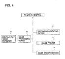
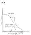
- Figs. 4 and 5 The X-ray image radiographing apparatus of the present invention is shown in Figs. 4 and 5.
- Fig. 4 is a block diagram showing an outlined structure of the X-ray image radiographing apparatus.
- Fig. 5 is a diagram showing a relationship between the intensity of signal and the spatial frequency subjected to Fourier transform.
- the X-ray image radiographing apparatus comprises a digital X-ray image detector 10, an image processing means 11, CRT image displaying apparatus 12, an image printer 13 and an image storing apparatus 14.
- the image processing apparatus 11 conducts image processing for a digital X-ray image obtained by the digital X-ray image detector 10.
- the image processing by the image processing means 11 can be attained as follows.
- Edge sections peculiar to refraction contrast are detected by, for example, a pixel mask, and the contrast of the sections are expanded.
- a pattern of estimated refraction contrast is subjected to Fourier transform so as to obtain the frequency components as edge enhancement calculation values. Thereafter, in the frequency processing for the entire image, the frequency components corresponding to the refraction contrast are enhanced.
- the digital X-ray image subjected to the image processing in the above method are outputted to the CRT image displaying apparatus 12 and the image printer 13, and stored in the image recording apparatus 14 or transmitted to LAN in a hospital.
- the present invention can be preferably applied to medical service. That is, as described in Items (11) and (22), the object is a human body or a specimen sampled from a human body.
- the object is a breast or a specimen sampled from the breast.
- a X-ray tube having a molybdenum anode is used and the radiography is conducted with a magnification ratio of 1 to 2 times.
- the size of focal spot is preferably 100 ⁇ m to 600 ⁇ m.
- the distance between the X-ray tube and a X-ray detector is preferably not smaller than 0.3 m, even in an enlarging radiography, not exceeds 0.6 m. This conventional radiographing condition does not fully satisfy the radiographing condition of the present invention and could not obtain the boundary contrast enhanced image of the object.
- the X-ray tube is arranged to be horizontal so as to make the proceeding direction of the X-ray parallel to the ground and the object is placed with the distance R1, and then the X-ray detector is placed with the distance R2 from the object.
- a cylinder-shaped resin which has a diameter of 1 cm and contains bubbles therein and the tip of a circular cone-shaped pipette which is made of resin and having a diameter of 1 cm were used as objects and the radiographing was conducted for them.
- Figs. 6(a) and 6(b) are drawings prepared by imitating the photograph of the image of the inventive example submitted with a petition to submit a material.
- FIGs. 6(c) and 6(d) are also drawings prepared by imitating the photograph of the image of the comparative example submitted with a petition to submit a material.
- magnification of the image shown in Figs. 6(c) and 6(d) are the same as that of the image shown in Figs. 6(a) and 6(b).
- the periphery edge of the bubbles in the cylinder-shaped resin are recognized as being white.
- the periphery at the inside of curved surface is enhanced to be white.
- the edge is enhance to be white or to be black is determined depending on which one of refractive indexes of the two materials is larger. In the present invention, in any case of white or black, the edge enhancement can be obtained.
- the film CMH produced by Konica Corp. and the intensifying screen M100 produced by Konica Corp. were used. After radiographing, the developing processing was conducted by Konica-manufactured SRX-503 at the temperature of 34 °c. After, the developing processing, the samples were hanged up in the light box of fluorescent light (viewing lantern) and were judged with the naked eyes. The results are shown in Table 2.
- R1 ⁇ (D-7)/200 (m) when the size of focal spot is 100 ⁇ m, R1 is that R1 ⁇ 0.47. From Table 2, the present invention which satisfied the formula: R1 ⁇ (D-7)/200 (m) was evaluated so highly.
- the X-ray image radiography was conducted in accordance with Example 1 .
- the results were indicated in Table 3.
- a object 156 type mammographic phantom manufactured by RMI Corp. in compliance with ACR Standard is used.
- the film CMH produced by Konica Corp. was used.
- the phantom used in this example is prepared with the consideration for a breast of a human which is compressed in the thickness of about 4.5 cm.
- six units of nylon fibers imitating the fiber organization five units of oxidized aluminum speck imitating a group of micro calcified substances, and six units of nylon fibers imitating a tumor are stuffed in.
- the numbers summed up the numbers of observed substances becomes a score.
- the total number of 4 points in the fiber, 3 points in the speck and 3 points in the tumor is the lowest score in the full score of 16 points.
- the back densities are adjusted to be the same level of about 1.3. No.
- the detecting ability is increased.
- the amount of irradiation is the value representing how much amount of X-rays was the object irradiated with.
- 1R is an amount of X-ray to form a pair of ions of 2.1 x 10 9 pieces in the air of 1 cm 3 (0 °c, 1 atmospheric pressure).
- the amount of irradiation does not exceed 1000 mR from the view of the object exposed to X-ray.
- Example 4 By using the film New CM produced by Konica Cop. Having of 2.7, the experiment similar to that in Example 1 was conducted. In this example, the screen/film system was not used as the X-ray detector. Instead of it, the plate coated with a stimulable phosphor prepared on trial basis by Konica Corp. was used. After radiographing with X-ray, image information was read by irradiating the plate with laser on pitch of 87.5 ⁇ m. The read-out image signals are printed on a silver salt film by using the laser imager Li7 manufactured by Konica Corp and the developing process for the film was conducted by SRX-502. The size of the printed image was made equal to the actual size of the object and the printed image was observed. Thus obtained evaluation results are indicated in Table 4.
- the evaluation standard is the same as that in Example 2 , an intermediate delicate point between standard ranks is represented by, for example, 2-3. Further, the obtained edge sections of the image was subjected to an enhancement processing as shown in Fig. 5, in Item of Evaluation, the rank indicated in ( ) were obtained and in the result, the effect of the improvement was appreciated. In the image processing conducted here, edge enhancing components obtained previously by calculation was superimposed on the image signals subjected to Fourier transform so as to enhance the edge sections. No. R1(m) R2(m) Evaluation Magnification ratio Remarks 1 0.5 0.25 2-3(3) 1 Inv. 2 0.5 0.5 2-3(3) 1 Inv. 3 1.0 0.5 3(3) 1 Inv. 4 1.3 0.5 3(3-4) 1 Inv.
- the widely practical usable phase contrast X-ray image can be obtained in comparison with the conventional phase contrast X-ray image which is lack of actual usability in the operating site for medical service and inspection.
Landscapes
- Health & Medical Sciences (AREA)
- Life Sciences & Earth Sciences (AREA)
- Pathology (AREA)
- Nuclear Medicine, Radiotherapy & Molecular Imaging (AREA)
- Radiology & Medical Imaging (AREA)
- Physics & Mathematics (AREA)
- Medical Informatics (AREA)
- Engineering & Computer Science (AREA)
- General Health & Medical Sciences (AREA)
- Analytical Chemistry (AREA)
- Heart & Thoracic Surgery (AREA)
- General Physics & Mathematics (AREA)
- Biochemistry (AREA)
- Biophysics (AREA)
- High Energy & Nuclear Physics (AREA)
- Chemical & Material Sciences (AREA)
- Optics & Photonics (AREA)
- Biomedical Technology (AREA)
- Immunology (AREA)
- Molecular Biology (AREA)
- Surgery (AREA)
- Animal Behavior & Ethology (AREA)
- Public Health (AREA)
- Veterinary Medicine (AREA)
- Apparatus For Radiation Diagnosis (AREA)
- Analysing Materials By The Use Of Radiation (AREA)
- Image Processing (AREA)
Abstract
Description
wherein the fixing means is able to set such that a distance R1 between the X-ray tube and the position of the object fixed by the fixing means so as to be within a range defined by the following formula:
| LOWER LIMIT VALUES OF DISTANCE R1 BETWEEN X-RAY SOURCE AND OBJECT | |
| D(µm) | R1(m) |
| 30 | 0.12 |
| 50 | 0.22 |
| 100 | 0.47 |
| 200 | 0.99 |
| 500 | 2.47 |
| 800 | 3.97 |
| 1000 | 4.97 |
| No. | R1(m) | R2(m) | Evaluation | | Remarks | |
| 1 | 0.5 | 0.25 | 3 | 1.5 | Inv. | |
| 2 | 0.5 | 0.5 | 3 | 2 | Inv. | |
| 3 | 1.0 | 0.5 | 4 | 1.5 | Inv. | |
| 4 | 1.3 | 0.5 | 4 | 1.38 | Inv. | |
| 5 | 1.5 | 0.3 | 4 | 1.20 | Inv. | |
| 6 | 3 | 1.4 | 5 | 1.47 | Inv. | |
| 7 | 0.3 | 0.5 | 1 | 3 | Comp. | |
| 8 | 0.4 | 0.2 | 1 | 1.5 | Comp. | |
| 9 | 1.50 | 0.1 | 1 | 1.07 | Comp. | |
| 10 | 1.50 | 0 | 1 | 1.0 | Comp. |
| No. | Screen | R1 (m) | R2 (m) | Fiber | Speck | Tumo | Total | Magnification . ratio | Amount of | Remarks | |
| 1 | M100 | 0.6 | 0 | 5 | 4 | 3 | 12 | 1 | 526mR | Com. | |
| 2 | same above | 0.5 | 0.25 | 5 | 5 | 4 | 14 | 1.5 | 1716mR | Inv. | |
| 3 | same above | 1.0 | 0.5 | 6 | 5 | 5 | 16 | 1.5 | 3010mR | Inv. | |
| 4 | M200 | 0.6 | 0 | 4 | 4 | 4 | 12 | 1 | 263mR | Com. | |
| 5 | same above | 0.5 | 0.25 | 5 | 5 | 4 | 14 | 1.5 | 772mR | Inv. | |
| 6 | same above | 0.6 | 0.3 | 5 | 5 | 4 | 14 | 1.5 | 789mR | Inv. | |
| 7 | same above | 1.0 | 0.5 | 6 | 5 | 4 | 15 | 1.5 | 1118mR | Inv. | |
| 8 | SRO500 | 0.6 | 0 | 4 | 3 | 3 | 10 | 1 | 395mR | Com. | |
| 9 | same above | 1.0 | 0.5 | 6 | 5 | 4 | 15 | 1.5 | 688mR | Inv. |
| No. | R1(m) | R2(m) | Evaluation | | Remarks | |
| 1 | 0.5 | 0.25 | 2-3(3) | 1 | Inv. | |
| 2 | 0.5 | 0.5 | 2-3(3) | 1 | Inv. | |
| 3 | 1.0 | 0.5 | 3(3) | 1 | Inv. | |
| 4 | 1.3 | 0.5 | 3(3-4) | 1 | Inv. | |
| 5 | 1.5 | 0.3 | 4(4) | 1 | Inv. | |
| 6 | 3 | 1.4 | 4(4-5) | 1 | Inv. | |
| 7 | 0.3 | 0.5 | 1(1-2) | 1 | Comp. | |
| 8 | 0.4 | 0.2 | 1(1-2) | 1 | Comp. | |
| 9 | 1.50 | 0.1 | 1 | 1 | Comp. | |
| 10 | 1.50 | 0 | 1 | 1 | Comp. |
Claims (25)
- A X-ray image radiographing method of detecting a X-ray image passing an object irradiated with X-ray emitted from a X-ray tube by a X-ray detector, comprising:a step of increasing a sharpness of an image lowered due to penumbra by enhancing an edge of the image with refraction contrast enhancement.
- A X-ray image radiographing method, comprising steps of:using a X-ray tube having a size D of focal spot of 30 µm or more;setting a distance R1 between the X-ray tube and an object so as to be within a range defined by the following formula:setting a distance R2 between the object and a X-ray detector so as to be not smaller than 0.15 (m).
- The X-ray image radiographing method of claim 2, wherein the distance R1 between the X-ray tube and the object is set to be within a range defined by the following formula:
- The X-ray image radiographing method of claim 2 or 3, wherein the size of focal spot is 30 µm to 1000 µm.
- The X-ray image radiographing method of one of claims 2 to 4, wherein the size of focal spot is 50 µm to 500 µm.
- The X-ray image radiographing method of one of claims 2 to 5, wherein the energy of X-ray in a line spectrum is 10 keV to 60 keV.
- The X-ray image radiographing method of one of claims 2 to 6, wherein an anode of the X-ray tube contains molybdenum or rhodium.
- The X-ray image radiographing method of one of claims 2 to 6, wherein a screen/film system having an image contrastof 1.5 to 3.6 is used.

- The X-ray image radiographing method of one of claims 2 to 6, wherein a screen/film system having an image contrast
- The X-ray image radiographing method of one of claims 2 to 8, wherein a digital X-ray detector having a size of a pixel of 1 µm to 200 µm is used.
- The X-ray image radiographing method of claim 10, wherein an enhanced boundary portion of the object is detected from the obtained image data and a width of the boundary portion and/or image contrast is further enhanced.
- The X-ray image radiographing method of one of claims 2 to 11, wherein the object is a human body or a specimen sampled from a human body.
- The X-ray image radiographing method of one of claims 2 to 12, wherein the object is a breast or a specimen sampled from the breast.
- A X-ray image radiographing apparatus, comprising:a X-ray tube having a size of focal spot of 30 µm or more;a fixing means for fixing a position of an object to be radiographed; anda X-ray detector to detect a X-ray image passing through the object;
wherein the fixing means is able to set such that a distance R1 between the X-ray tube and the position of the object fixed by the fixing means so as to be within a range defined by the following formula: - The X-ray image radiographing apparatus of claim 14, wherein the distance R1 between the X-ray tube and the position of the object fixed by the fixing means is settable within a range defined by the following formula:
- The X-ray image radiographing apparatus of claim 14 or 15, wherein the size of focal spot is 30 µm to 1000 µm.
- The X-ray image radiographing apparatus of one of claims 14 to 16, wherein the size of focal spot is 50 µm to 500 µm.
- The X-ray image radiographing apparatus of one of claims 15 to 17, wherein energy of X-ray in a line spectrum is 10 keV to 60 keV.
- The X-ray image radiographing apparatus of one of claims 15 to 18, wherein an anode of the X-ray tube contains molybdenum or rhodium.
- The X-ray image radiographing apparatus of one of claims 14 to 19, wherein a screen/film system having an image contrast
G of 1.5 to 3.6 is used. - The X-ray image radiographing apparatus of one of claims 14 to 19, wherein a screen/film system having an image contrast
G of 1.5 to 4.0 is used. - The X-ray image radiographing apparatus of one of claims 14 to 21, wherein a digital X-ray detector having a size of a pixel of 1 µm to 200 µm is used.
- The X-ray image radiographing apparatus of claim 22, wherein an enhanced boundary portion of the object is detected from the obtained image data and a width of the boundary portion and/or image contrast is further enhanced.
- The X-ray image radiographing apparatus of one of claims 14 to 23, wherein the object is a human body or a specimen sampled from a human body.
- The X-ray image radiographing apparatus of claim 14, wherein the object is a breast or a specimen sampled from the breast.
Priority Applications (1)
| Application Number | Priority Date | Filing Date | Title |
|---|---|---|---|
| DE60036161T DE60036161T3 (en) | 1999-07-16 | 2000-07-10 | Method for taking X-ray images |
Applications Claiming Priority (2)
| Application Number | Priority Date | Filing Date | Title |
|---|---|---|---|
| JP20396999 | 1999-07-16 | ||
| JP20396999 | 1999-07-16 |
Publications (4)
| Publication Number | Publication Date |
|---|---|
| EP1069429A2 true EP1069429A2 (en) | 2001-01-17 |
| EP1069429A3 EP1069429A3 (en) | 2003-06-25 |
| EP1069429B1 EP1069429B1 (en) | 2007-08-29 |
| EP1069429B2 EP1069429B2 (en) | 2011-10-19 |
Family
ID=16482645
Family Applications (1)
| Application Number | Title | Priority Date | Filing Date |
|---|---|---|---|
| EP00114791A Expired - Lifetime EP1069429B2 (en) | 1999-07-16 | 2000-07-10 | X-ray image radiographing method |
Country Status (3)
| Country | Link |
|---|---|
| US (1) | US7190761B1 (en) |
| EP (1) | EP1069429B2 (en) |
| DE (1) | DE60036161T3 (en) |
Cited By (4)
| Publication number | Priority date | Publication date | Assignee | Title |
|---|---|---|---|---|
| EP1764038A4 (en) * | 2004-07-07 | 2010-03-24 | Toshiba Kk | X-ray inspecting method and x-ray inspecting device |
| EP1935341A4 (en) * | 2005-10-12 | 2011-04-20 | Konica Minolta Med & Graphic | Radiographic imager |
| US8009892B2 (en) | 2006-08-22 | 2011-08-30 | Konica Minolta Medical & Graphic, Inc. | X-ray image processing system |
| DE102009013389B4 (en) | 2008-03-27 | 2018-12-13 | Mitsubishi Electric Corp. | Apparatus and method for classification based on the presence or absence of bromine and methods of processing a recycled synthetic resin material |
Families Citing this family (1)
| Publication number | Priority date | Publication date | Assignee | Title |
|---|---|---|---|---|
| JP7724089B2 (en) * | 2021-06-28 | 2025-08-15 | 浜松ホトニクス株式会社 | X-ray focal point shape evaluation device and X-ray focal point shape evaluation method |
Citations (2)
| Publication number | Priority date | Publication date | Assignee | Title |
|---|---|---|---|---|
| WO1996031098A1 (en) | 1995-03-28 | 1996-10-03 | Commonwealth Scientific And Industrial Research Organisation | Simplified conditions and configurations for phase-contrast imaging with hard x-rays |
| JPH10248833A (en) | 1996-03-29 | 1998-09-22 | Hitachi Ltd | Phase contrast X-ray imaging device |
Family Cites Families (8)
| Publication number | Priority date | Publication date | Assignee | Title |
|---|---|---|---|---|
| US2650308A (en) * | 1953-08-25 | Method of and apparatus foe ascer | ||
| NL8301839A (en) * | 1983-05-25 | 1984-12-17 | Philips Nv | ROENTGEN TUBE WITH TWO CONSEQUENT LAYERS OF ANODE MATERIAL. |
| US4979198A (en) * | 1986-05-15 | 1990-12-18 | Malcolm David H | Method for production of fluoroscopic and radiographic x-ray images and hand held diagnostic apparatus incorporating the same |
| IL93215A0 (en) * | 1990-01-30 | 1990-11-05 | Elscint Ltd | Biopsy needle positioning device |
| US5305365A (en) * | 1992-11-24 | 1994-04-19 | Bennett X-Ray Technologies | Mammography system with rearwardly tilting mammograph |
| US5802137A (en) * | 1993-08-16 | 1998-09-01 | Commonwealth Scientific And Industrial Research | X-ray optics, especially for phase contrast imaging |
| JPH09187455A (en) * | 1996-01-10 | 1997-07-22 | Hitachi Ltd | Phase type X-ray CT system |
| ATE422285T1 (en) * | 1996-12-24 | 2009-02-15 | Xrt Ltd | PHASE DETERMINATION IN A PHASE IMAGING PROCESS |
-
2000
- 2000-07-10 DE DE60036161T patent/DE60036161T3/en not_active Expired - Lifetime
- 2000-07-10 EP EP00114791A patent/EP1069429B2/en not_active Expired - Lifetime
- 2000-07-14 US US09/616,608 patent/US7190761B1/en not_active Expired - Fee Related
Patent Citations (2)
| Publication number | Priority date | Publication date | Assignee | Title |
|---|---|---|---|---|
| WO1996031098A1 (en) | 1995-03-28 | 1996-10-03 | Commonwealth Scientific And Industrial Research Organisation | Simplified conditions and configurations for phase-contrast imaging with hard x-rays |
| JPH10248833A (en) | 1996-03-29 | 1998-09-22 | Hitachi Ltd | Phase contrast X-ray imaging device |
Cited By (5)
| Publication number | Priority date | Publication date | Assignee | Title |
|---|---|---|---|---|
| EP1764038A4 (en) * | 2004-07-07 | 2010-03-24 | Toshiba Kk | X-ray inspecting method and x-ray inspecting device |
| EP1935341A4 (en) * | 2005-10-12 | 2011-04-20 | Konica Minolta Med & Graphic | Radiographic imager |
| US8009892B2 (en) | 2006-08-22 | 2011-08-30 | Konica Minolta Medical & Graphic, Inc. | X-ray image processing system |
| CN101129266B (en) * | 2006-08-22 | 2011-11-16 | 柯尼卡美能达医疗印刷器材株式会社 | X-ray image processing system |
| DE102009013389B4 (en) | 2008-03-27 | 2018-12-13 | Mitsubishi Electric Corp. | Apparatus and method for classification based on the presence or absence of bromine and methods of processing a recycled synthetic resin material |
Also Published As
| Publication number | Publication date |
|---|---|
| DE60036161T2 (en) | 2008-05-21 |
| DE60036161D1 (en) | 2007-10-11 |
| EP1069429A3 (en) | 2003-06-25 |
| EP1069429B2 (en) | 2011-10-19 |
| DE60036161T3 (en) | 2012-04-19 |
| US7190761B1 (en) | 2007-03-13 |
| EP1069429B1 (en) | 2007-08-29 |
Similar Documents
| Publication | Publication Date | Title |
|---|---|---|
| US5276726A (en) | Method of and apparatus for standardizing and monitoring image quality in mammography | |
| US7010092B2 (en) | Dual energy imaging using optically coupled digital radiography system | |
| US5844965A (en) | Method and apparatus for using film density measurements of a radiograph to monitor the reproducibility of X-ray exposure parameters of a mammography unit | |
| JPH04300525A (en) | Quantitative analysis of osteosalt | |
| US5544238A (en) | Method of and apparatus for standardizing and monitoring beam quality in mammography | |
| JP3861572B2 (en) | X-ray imaging device | |
| US6404848B1 (en) | X-ray image radiographing method and X-ray image radiographing apparatus | |
| JP2003180670A (en) | Digital phase-contrasted x-ray imaging system | |
| US7190761B1 (en) | X-ray image radiographing method and radiographing apparatus | |
| US6931099B2 (en) | High-energy X-ray imaging device and method therefor | |
| JP4010101B2 (en) | X-ray imaging device | |
| JP2003093377A (en) | Method for photographing x-ray image and system for photographing x-ray image | |
| KR102234196B1 (en) | Methods for non-destructive testing of wooden cultural assets that can be evaluated on image quality | |
| Neitzel et al. | Comparison of low-contrast detail detectability with five different conventional and digital radiographic imaging systems | |
| JP2004248699A (en) | X-ray imaging method and x-ray imaging system | |
| Lewis et al. | Diffraction-enhanced imaging: improved contrast and lower dose X-ray imaging | |
| Bunch | Objective imaging characteristics of mammographic screen-film systems | |
| JP2008018155A (en) | X-ray equipment | |
| JP2002085389A (en) | X-ray imaging system and method | |
| Wakoh et al. | A dual sensitivity screen system for TMJ image enhancement in cephalometric radiography: sensitometric evaluation | |
| KR100846008B1 (en) | X-ray inspection method and X-ray inspection apparatus | |
| أسماء سعيد أبوعجيلة المهدي | Quality Control Of Film Processing in medical x-ray imaging | |
| JPH0772565A (en) | X-ray image pickup device | |
| JP3901409B2 (en) | X-ray image photographing method and apparatus, and silver halide photographic light-sensitive material for mammography | |
| AU682944B2 (en) | Screen film cassette |
Legal Events
| Date | Code | Title | Description |
|---|---|---|---|
| PUAI | Public reference made under article 153(3) epc to a published international application that has entered the european phase |
Free format text: ORIGINAL CODE: 0009012 |
|
| AK | Designated contracting states |
Kind code of ref document: A2 Designated state(s): AT BE CH CY DE DK ES FI FR GB GR IE IT LI LU MC NL PT SE |
|
| AX | Request for extension of the european patent |
Free format text: AL;LT;LV;MK;RO;SI |
|
| PUAL | Search report despatched |
Free format text: ORIGINAL CODE: 0009013 |
|
| AK | Designated contracting states |
Designated state(s): AT BE CH CY DE DK ES FI FR GB GR IE IT LI LU MC NL PT SE |
|
| AX | Request for extension of the european patent |
Extension state: AL LT LV MK RO SI |
|
| RIC1 | Information provided on ipc code assigned before grant |
Ipc: 7G 06T 5/00 B Ipc: 7G 01N 23/04 A Ipc: 7A 61B 6/02 B Ipc: 7G 01N 23/20 B |
|
| 17P | Request for examination filed |
Effective date: 20031219 |
|
| AKX | Designation fees paid |
Designated state(s): DE FR GB |
|
| GRAP | Despatch of communication of intention to grant a patent |
Free format text: ORIGINAL CODE: EPIDOSNIGR1 |
|
| GRAS | Grant fee paid |
Free format text: ORIGINAL CODE: EPIDOSNIGR3 |
|
| GRAA | (expected) grant |
Free format text: ORIGINAL CODE: 0009210 |
|
| AK | Designated contracting states |
Kind code of ref document: B1 Designated state(s): DE FR GB |
|
| REG | Reference to a national code |
Ref country code: GB Ref legal event code: FG4D |
|
| REF | Corresponds to: |
Ref document number: 60036161 Country of ref document: DE Date of ref document: 20071011 Kind code of ref document: P |
|
| ET | Fr: translation filed | ||
| PLBI | Opposition filed |
Free format text: ORIGINAL CODE: 0009260 |
|
| PLAX | Notice of opposition and request to file observation + time limit sent |
Free format text: ORIGINAL CODE: EPIDOSNOBS2 |
|
| 26 | Opposition filed |
Opponent name: YXLON INTERNATIONAL GMBH Effective date: 20080529 |
|
| PLAF | Information modified related to communication of a notice of opposition and request to file observations + time limit |
Free format text: ORIGINAL CODE: EPIDOSCOBS2 |
|
| PLBB | Reply of patent proprietor to notice(s) of opposition received |
Free format text: ORIGINAL CODE: EPIDOSNOBS3 |
|
| RTI2 | Title (correction) |
Free format text: X-RAY IMAGE RADIOGRAPHING METHOD |
|
| PUAH | Patent maintained in amended form |
Free format text: ORIGINAL CODE: 0009272 |
|
| STAA | Information on the status of an ep patent application or granted ep patent |
Free format text: STATUS: PATENT MAINTAINED AS AMENDED |
|
| 27A | Patent maintained in amended form |
Effective date: 20111019 |
|
| AK | Designated contracting states |
Kind code of ref document: B2 Designated state(s): DE FR GB |
|
| REG | Reference to a national code |
Ref country code: DE Ref legal event code: R102 Ref document number: 60036161 Country of ref document: DE |
|
| REG | Reference to a national code |
Ref country code: DE Ref legal event code: R102 Ref document number: 60036161 Country of ref document: DE Effective date: 20111019 |
|
| REG | Reference to a national code |
Ref country code: FR Ref legal event code: PLFP Year of fee payment: 16 |
|
| PGFP | Annual fee paid to national office [announced via postgrant information from national office to epo] |
Ref country code: GB Payment date: 20150708 Year of fee payment: 16 Ref country code: DE Payment date: 20150707 Year of fee payment: 16 |
|
| PGFP | Annual fee paid to national office [announced via postgrant information from national office to epo] |
Ref country code: FR Payment date: 20150629 Year of fee payment: 16 |
|
| REG | Reference to a national code |
Ref country code: DE Ref legal event code: R119 Ref document number: 60036161 Country of ref document: DE |
|
| GBPC | Gb: european patent ceased through non-payment of renewal fee |
Effective date: 20160710 |
|
| PG25 | Lapsed in a contracting state [announced via postgrant information from national office to epo] |
Ref country code: FR Free format text: LAPSE BECAUSE OF NON-PAYMENT OF DUE FEES Effective date: 20160801 Ref country code: DE Free format text: LAPSE BECAUSE OF NON-PAYMENT OF DUE FEES Effective date: 20170201 |
|
| REG | Reference to a national code |
Ref country code: FR Ref legal event code: ST Effective date: 20170331 |
|
| PG25 | Lapsed in a contracting state [announced via postgrant information from national office to epo] |
Ref country code: GB Free format text: LAPSE BECAUSE OF NON-PAYMENT OF DUE FEES Effective date: 20160710 |