EP1069412A2 - Weighing apparatus for weighing of goods on vehicles - Google Patents
Weighing apparatus for weighing of goods on vehicles Download PDFInfo
- Publication number
- EP1069412A2 EP1069412A2 EP00114642A EP00114642A EP1069412A2 EP 1069412 A2 EP1069412 A2 EP 1069412A2 EP 00114642 A EP00114642 A EP 00114642A EP 00114642 A EP00114642 A EP 00114642A EP 1069412 A2 EP1069412 A2 EP 1069412A2
- Authority
- EP
- European Patent Office
- Prior art keywords
- weighing
- parts
- weighing device
- force
- weight
- Prior art date
- Legal status (The legal status is an assumption and is not a legal conclusion. Google has not performed a legal analysis and makes no representation as to the accuracy of the status listed.)
- Granted
Links
Images


Classifications
-
- G—PHYSICS
- G01—MEASURING; TESTING
- G01G—WEIGHING
- G01G19/00—Weighing apparatus or methods adapted for special purposes not provided for in the preceding groups
- G01G19/08—Weighing apparatus or methods adapted for special purposes not provided for in the preceding groups for incorporation in vehicles
Definitions
- the invention relates to a weighing device for weighing Goods on vehicles, in particular on body parts for road vehicles according to the preamble of claim 1.
- Such a weighing method on the vehicle is known from EP 0 573 420 B1 known. There is the load or weight of the vehicle and its loading using a so-called direct weighing technique determined. These are directly on the rigid frame of the vehicle chassis transducer attached, located nearby the suspension points between the chassis and the axles. With these transducers the deformation of the frame measured, which is proportional to the load or weight is.
- Such a weighing method is very simple, but too imprecise for more accurate verifiable weighing systems. In particular, an accurate measurement with inclined stands is likely Vehicles only with a larger computational evaluation process to be possible.
- DE 29 521 150 U1 describes a weighing device for a Vehicle known in the case between the bodies to be weighed and one or more load cells are arranged in the vehicle chassis with which the weight of the superstructure or its content can be determined. To do this, the vehicle must be horizontal stand straight on a surface or it is with Provided with the aid of an inclination sensor and arithmetic circuits, correct the skewness arithmetically. For horizontal Restraint of the structure when the vehicle is not inclined is additional still provided, the superstructures opposite the vehicle chassis horizontal handlebars against lateral displacement to secure. Such an inclination correction has the Disadvantage that an inclination sensor also causes a measurement error, the additional weighing result via the correction calculations adulterated. In addition, the horizontal fixation with the help of the handlebars very complex and it can cause additional measurement errors due to force shunt effects enter.
- the invention is therefore based on the object of a weighing device of the type mentioned at the outset the influence of the inclination of the vehicle on the measurement error Minimum reduced and this with the simplest design.
- the invention has the advantage that the pendulum suspended Load cells the weight of the vehicle body Always align the load cells in the direction of gravity and this regardless of the vehicle inclination. There is an inclination correction to determine the weight of the superstructure or its content can be dispensed with. Furthermore, be more advantageous Way through the swinging suspension of the load cells the vehicle bodies vertical and in relation to the vehicle frame a predetermined area also fixed horizontally so that Handlebars and the like as anti-lift and limiting means are not required for horizontal displacement. Such an oscillating suspension of the load cells therefore detects the weight to be measured also advantageously Inclination of the vehicle without force shunt so that high-precision verifiable weight measurement is also possible is.
- the weighing device with rod-shaped, rotationally symmetrical load cells is advantageous a space-saving arrangement on the side of the standard frame elements of the vehicles possible, because even in proportion the load cells are relatively high have a slim design. With such an execution can the oscillating storage in an advantageous manner also in the force transmission and force transmission elements be integrated or simply connected to them become.
- load cells When using such rotationally symmetrical rod-shaped It is particularly advantageous for load cells to have good ones Have permanent load properties, so that these also Driving operation can remain in the power flow and so easily reproducible Deliver measured values. Otherwise, these are load cells easy and inexpensive to manufacture and also dynamic Relatively insensitive to loads.
- Fig. 1 of the drawing is an arrangement of a weighing device shown on a vehicle, consisting of four load cell devices 3, 6 between the vehicle frame 2 and the vehicle body consists, the structure oscillating on the four load cell devices 3, 6 is suspended.
- the vehicle shown is a truck 1, whose vehicle body is designed as a loading area 5 is.
- the weighing device can also be used for railbound and other vehicles.
- the one shown Truck 1 has a under the bed 5 Frame 2, which has a longitudinal spar 4 on each side the two load cell devices 3, 6 are arranged.
- the four load cell devices 3, 6 support the vehicle body 5 and fix at four points opposite the vehicle frame 2 this largely in its vertical and horizontal position.
- the loading area 5 is opposite the frame 2 through the Load cell devices 3, 6 suspended like a handlebar, so that a lateral displacement range of approx. 10 to 20 mm is provided is the load cell device when the vehicle 1 is in an inclined position 3, 6 always aligned in the direction of gravity.
- This lateral displacement area covers all directions and is substantially the axial length of the load cell device 3, 6 dependent.
- a load cell device 3, 6 with a rod-shaped load cell with spherical joints usually has a length of about 100 to 200 mm, so that a sideways shift range from 10 to 20 mm is sufficient to always have a vertical alignment in To ensure the direction of gravity.
- the weighing device shown there are four load cell devices 3, 6 at the corner areas under the vehicle body 5 arranged, which are interconnected so that they a Deliver a signal that is directly related to the weight of the body 5 together with its content is proportional.
- the weighing device can but also from three or more than four load cell devices 3, 6 exist.
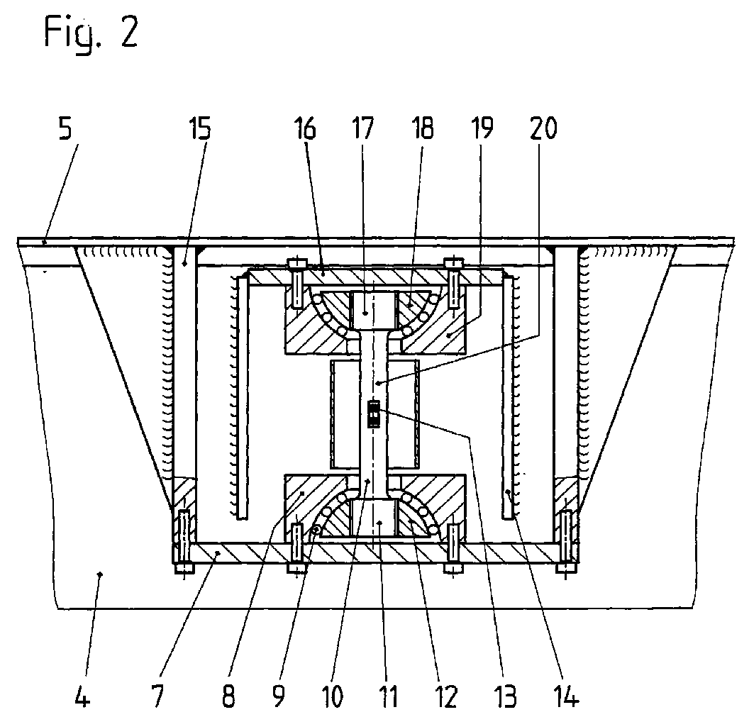
- Part of the vehicle body 5 is in the upper area can be seen on which a downward-facing rectangular Tag 15 from flat sheet metal parts is attached.
- This remodeling 15 has a horizontal sheet metal part on its lower part 7, which is connected to the vertical sheet metal parts and to which a weight sensor 10 is attached.
- the entire load cell device 3, 6 from the conversion parts 15, 14, the weight sensor 10 with its attachment and evaluation parts can also be provided as a module unit and over Connecting elements on vehicle body 5 and vehicle frame 2 be attached.
- the weight sensor 10 consists essentially of a rod-shaped deformation body 20, on the strain gauge 13 are applied and with force introduction and force transmission parts connected is.
- the deformation body is as Round rod 20 formed, the top and bottom in a threaded part 11, 17 expires.
- the deformation body can also be square, rectangular or modified cross-sectional shapes exhibit.
- the threaded part 11, 17 is each with a spherical connected to the outside arched bearing element 12, 18 and forms a force application and force transmission part.
- the spherical bearing elements 12, 18 are also spherical Counter bearing elements 8, 19 arranged, however, inwards are arched and thus the shape of the force introduction 12th and diversion elements 18 are adapted and form so-called Axial spherical plain bearings.
- Ball bearings 9 are provided between the bearing 12, 18 and counter bearing elements 8, 19 for reducing friction. To reduce friction are also low-friction plastics such as polytetrafluoroethylene (PTFE) or lubricants can be used.
- the counter bearing elements 8, 19 are each via a detachable connection attached to the horizontal conversion parts 7, 16.
- FIG. 3 of the drawing is a load cell device 3, 6 shown as a sectional view from the direction of travel. 3 the drawing are the same as shown in Fig. 2 Parts have the same reference numbers.
- the rotationally symmetrical weight sensor 10 laterally next to the U-shaped longitudinal beam 4 of the vehicle frame 2 and arranged connected to this via the smaller rectangular tag 16.
- the larger conversion 15 in the upper area Vehicle body 5 attached. Between the vehicle body 5 and the vehicle frame 2 as well as between the conversion part 15, 14 is a vertical 21 and horizontal distance 22 of approximately 10 up to 20 mm provided in order to tilt the vehicle 1 shows a vertical alignment of the weight sensors 10 enable. These distances 21, 22 are only during weighing necessary.
- the vehicle body 5 is at least in a horizontal Fixed location. You can do this, not shown, vertically trained conical bolts are provided from below through holes in the side member 4 in holes in the body 5 be put.
- Such a locking device can also automatically via a hydraulic or pneumatic cylinder or any other type of drive. To do this at the same time electronic switching and display devices provided that only allow body weighing if the locking device is released so that the structure 5 gravity-free in the direction of gravity due to gravity is aligned. On the other hand is defined by a Weight display shows the driver that the Structure secured by the lock for driving is.
- the locking device can also be hydraulic or Pneumatic cylinders or inflatable rubber bellows or with any Drives take place that the lateral horizontal Spaces 21 between the conversion parts 15, 14 or the conversion parts 15, 14 and fill or reduce the vehicle frame 2.
- the structure 5 can be locked opposite the vehicle frame 2 is also made by cable pull systems, which are loosened to weigh the superstructure 5 or the goods.
- the weight sensor 10 is advantageously a rod-shaped largely rotationally symmetrical load cell used, 20 strain gauges on their circumference in the central area of the rod 13 are applied.
- the deformation of the load cells 10 generate a signal in the strain gauges 13, that is proportional to the weight force introduced.
- load cells can also be used that are suspended in this way, that the structure is always aligned in the measuring direction. So can between the spherical force 12 and force diversion elements 18 also rotationally symmetrical jump ring or Bending beam load cells are arranged with the weight of the structure 5 and its content can be detected.
- the force 12 and force elements 18 do not have to spherical, but can also be a universal joint, as tapered tip bearings, self-aligning ball bearings or similar Execution be trained. It just has to a largely friction-free storage after all horizontal Pages are provided between which the load cells are arranged are.
Landscapes
- Physics & Mathematics (AREA)
- General Physics & Mathematics (AREA)
- Vehicle Body Suspensions (AREA)
- Testing Of Balance (AREA)
Abstract
Wägeeinrichtung zum Verwiegen von Gütern auf Fahrzeugaufbauteilen
(5), bei dem zwischen den zu wiegenden Aufbauteilen (5)
und einem Fahrzeugrahmen (2) vier Wägezellenvorrichtungen (3,
6) vorgesehen sind, die aus einem Gewichtskraftaufnehmer (10)
und Lagerelementen bestehen. Dabei sind die Krafteinleitungs- und
Kraftausleitungsteile der Gewichtskraftaufnehmer (10) als
pendelnde Lagerelemente ausgebildet oder mit solchen pendelnden
Lagerelementen (12, 18) verbunden, durch die der Gewichtskraftaufnehmer
(10) mit Hilfe der Schwerkraft stets so ausgerichtet
wird, daß die Gewichtskraftrichtung stets in Hauptmeßrichtung
verläuft. Die pendelnden Lagerelemente sind dabei
sphärisch ausgebildet, so daß die Kraftmeßvorrichtung (10) den
Fahrzeugaufbau (5) pendelnd mit dem Fahrzeugrahmen verbindet,
wodurch der Fahrzeugaufbau (5) stets in Schwerkraftrichtung
ausrichtbar ist.
Description
Die Erfindung betrifft eine Wägeeinrichtung zum Verwiegen von
Gütern auf Fahrzeugen, insbesondere auf Aufbauteilen bei Straßenfahrzeugen
gemäß dem Oberbegriff des Patentanspruchs 1.The invention relates to a weighing device for weighing
Goods on vehicles, in particular on body parts for road vehicles
according to the preamble of
Die genaue Messung von zugeladenen Gütern auf Lastkraftwagen und anderen Fahrzeugen wird meist mit stationären Fahrzeugwaagen ermittelt. Dazu muß das gesamte Fahrzeug bei Zu- oder Abladungen mindestens zweimal verwogen werden, woraus die Zu- oder Abladung als Differenzgewicht errechenbar ist. Vielfach sind derartige stationäre Waagen auch nicht vor Ort, so daß zeitaufwendige Anfahrwege in Kauf genommen werden müssen. In bestimmten Fällen ist es deshalb wünschenswert, die Zu- oder Abladung direkt am Fahrzeug zu ermitteln.The exact measurement of loaded goods on trucks and other vehicles is mostly with stationary vehicle scales determined. To do this, the entire vehicle must be loaded or unloaded be weighed at least twice, from which the feed or Unloading can be calculated as a differential weight. Often are such stationary scales not on site, so that time-consuming approaches have to be accepted. In In certain cases it is therefore desirable to add or Determine unloading directly on the vehicle.
Ein derartiges Wägeverfahren am Fahrzeug ist aus der EP 0 573 420 B1 bekannt. Dort wird die Last oder das Gewicht des Fahrzeugs und seiner Ladung mit Hilfe einer sogenannten Direktwägetechnik ermittelt. Dazu sind unmittelbar am starren Rahmen des Fahrzeugchassis Aufnehmer angebracht, die sich in der Nähe der Aufhängepunkte zwischen dem Chassis und den Achsen befinden. Mit diesen Aufnehmern wird die Verformung des Rahmens gemessen, der proportional der Belastung bzw. des Gewichts ist. Ein derartiges Wägeverfahren ist zwar sehr einfach ausgebildet, aber für genauere eichfähige Wägesysteme zu ungenau. Insbesondere dürfte eine genaue Messung bei schräg stehenden Fahrzeugen nur mit größerem rechnerischem Auswerteverfahren möglich sein. Such a weighing method on the vehicle is known from EP 0 573 420 B1 known. There is the load or weight of the vehicle and its loading using a so-called direct weighing technique determined. These are directly on the rigid frame of the vehicle chassis transducer attached, located nearby the suspension points between the chassis and the axles. With these transducers the deformation of the frame measured, which is proportional to the load or weight is. Such a weighing method is very simple, but too imprecise for more accurate verifiable weighing systems. In particular, an accurate measurement with inclined stands is likely Vehicles only with a larger computational evaluation process to be possible.
Aus der DE 29 521 150 U1 ist eine Wägevorrichtung für ein Fahrzeug bekannt, bei dem zwischen den zu wiegenden Aufbauten und dem Fahrzeugchassis eine oder mehrere Wägezellen angeordnet sind, mit denen das Gewicht der Aufbauten bzw. dessen Inhalt ermittelt werden kann. Dazu muß das Fahrzeug aber waagerecht gerade auf einem Untergrund stehen oder es ist mit Hilfe eines Neigungssensors und Rechenschaltungen vorgesehen, den Schiefstand rechnerisch zu korrigieren. Zur horizontalen Fesselung des Aufbaus beim Schiefstand des Fahrzeugs ist zusätzlich noch vorgesehen, die Aufbauten gegenüber dem Fahrzeugchassis horizontalen Lenkern gegen eine seitliche Verschiebung zu sichern. Eine derartige Neigungskorrektur hat den Nachteil, daß auch ein Neigungssensor einen Meßfehler verursacht, der über die Korrekturrechnungen das Wägeergebnis zusätzlich verfälscht. Darüber hinaus ist die horizontale Fixierung mit Hilfe der Lenker konstruktiv sehr aufwendig und es können noch zusätzliche Meßfehler durch Kraftnebenschlußwirkungen eintreten.DE 29 521 150 U1 describes a weighing device for a Vehicle known in the case between the bodies to be weighed and one or more load cells are arranged in the vehicle chassis with which the weight of the superstructure or its content can be determined. To do this, the vehicle must be horizontal stand straight on a surface or it is with Provided with the aid of an inclination sensor and arithmetic circuits, correct the skewness arithmetically. For horizontal Restraint of the structure when the vehicle is not inclined is additional still provided, the superstructures opposite the vehicle chassis horizontal handlebars against lateral displacement to secure. Such an inclination correction has the Disadvantage that an inclination sensor also causes a measurement error, the additional weighing result via the correction calculations adulterated. In addition, the horizontal fixation with the help of the handlebars very complex and it can cause additional measurement errors due to force shunt effects enter.
Der Erfindung liegt deshalb die Aufgabe zugrunde, eine Wägeeinrichtung der eingangs genannten Art zu schaffen, bei der der Einfluß der Schräglage des Fahrzeugs den Meßfehler auf ein Minimum reduziert und dies bei einfachster Ausgestaltung.The invention is therefore based on the object of a weighing device of the type mentioned at the outset the influence of the inclination of the vehicle on the measurement error Minimum reduced and this with the simplest design.
Diese Aufgabe wird durch die im Patentanspruch 1 angegebene
Erfindung gelöst. Weiterbildungen und vorteilhafte Ausführungsbeispiele
der Erfindung sind in den Unteransprüchen
angegeben.This object is achieved by the specified in
Die Erfindung hat den Vorteil, daß durch die pendelnd aufgehängten Wägezellen die Gewichtskraft des Fahrzeugaufbaus die Wägezellen stets in Schwerkraftrichtung ausrichtet und dies unabhängig von der Fahrzeugneigung. Dabei ist eine Neigungskorrektur zur Feststellung des Gewichts der Aufbauten bzw. dessen Inhalts entbehrlich. Weiterhin werden in vorteilhafter Weise durch die pendelnde Aufhängung der Wägezellen die Fahrzeugaufbauten gegenüber dem Fahrzeugrahmen vertikal und in einem vorgegebenen Bereich auch horizontal fixiert, so daß Lenker und dergleichen als Abhebesicherung und Begrenzungsmittel zur Horizontalverschiebung nicht erforderlich sind. Eine derartige pendelnde Aufhängung der Wägezellen erfaßt deshalb in vorteilhafter Weise das zu messende Gewicht auch bei Schrägstellung des Fahrzeugs kraftnebenschlußfrei, so daß damit auch eine hochgenaue eichfähige Gewichtsmessung möglich ist.The invention has the advantage that the pendulum suspended Load cells the weight of the vehicle body Always align the load cells in the direction of gravity and this regardless of the vehicle inclination. There is an inclination correction to determine the weight of the superstructure or its content can be dispensed with. Furthermore, be more advantageous Way through the swinging suspension of the load cells the vehicle bodies vertical and in relation to the vehicle frame a predetermined area also fixed horizontally so that Handlebars and the like as anti-lift and limiting means are not required for horizontal displacement. Such an oscillating suspension of the load cells therefore detects the weight to be measured also advantageously Inclination of the vehicle without force shunt so that high-precision verifiable weight measurement is also possible is.
Bei einer besonderen Ausführungsform der Wägeeinrichtung mit stabförmigen rotationssymmetrischen Wägezellen ist vorteilhafterweise eine platzsparende Anordnung seitlich an den Standardrahmenelementen der Fahrzeuge möglich, da auch bei verhältnismäßig hohen Nennlasten die Wägezellen eine verhältnismäßig schlanke Bauweise aufweisen. Bei einer derartigen Ausführung kann die pendelnde Lagerung in vorteilhafter Weise auch gleich mit in den Krafteinleitungs- und Kraftausleitungselementen integriert sein oder einfach mit diesen verbunden werden.In a special embodiment of the weighing device with rod-shaped, rotationally symmetrical load cells is advantageous a space-saving arrangement on the side of the standard frame elements of the vehicles possible, because even in proportion the load cells are relatively high have a slim design. With such an execution can the oscillating storage in an advantageous manner also in the force transmission and force transmission elements be integrated or simply connected to them become.
Beim Einsatz derartiger rotationssymmetrischer stabförmiger Wägezellen ist es insbesondere vorteilhaft, daß diese gute Dauerbelastungseigenschaften besitzen, so daß diese auch im Fahrbetrieb im Kraftfluß verbleiben können und so gut reproduzierbare Meßwerte liefern. Im übrigen sind diese Wägezellen einfach und kostengünstig herstellbar und auch gegenüber dynamischen Belastungen verhältnismäßig unempfindlich.When using such rotationally symmetrical rod-shaped It is particularly advantageous for load cells to have good ones Have permanent load properties, so that these also Driving operation can remain in the power flow and so easily reproducible Deliver measured values. Otherwise, these are load cells easy and inexpensive to manufacture and also dynamic Relatively insensitive to loads.
Die Erfindung wird anhand eines Ausführungsbeispiels, das in der Zeichnung dargestellt ist, näher erläutert. Es zeigen:
- Fig. 1:
- Eine Anordnung einer Wägeeinrichtung zur Aufbauverwiegung an einem Lastkraftwagen;
- Fig. 2:
- ein Schnittbild der Wägezellenvorrichtung längs zur Fahrtrichtung und
- Fig. 3:
- ein Schnittbild der Wägezellenvorrichtung quer zur Fahrtrichtung.
- Fig. 1:
- An arrangement of a weighing device for body weighing on a truck;
- Fig. 2:
- a sectional view of the load cell device along the direction of travel and
- Fig. 3:
- a sectional view of the load cell device transverse to the direction of travel.
In Fig. 1 der Zeichnung ist eine Anordnung einer Wägeeinrichtung
an einem Fahrzeug dargestellt, die aus vier Wägezellenvorrichtungen
3, 6 zwischen dem Fahrzeugrahmen 2 und dem Fahrzeugaufbau
besteht, wobei der Aufbau pendelnd an den vier Wägezellenvorrichtungen
3, 6 aufgehängt ist.In Fig. 1 of the drawing is an arrangement of a weighing device
shown on a vehicle, consisting of four
Bei dem dargestellten Fahrzeug handelt es sich um einen Lastkraftwagen
1, dessen Fahrzeugaufbau als Ladefläche 5 ausgebildet
ist. Die Wägevorrichtung kann aber auch bei schienengebundenen
und anderen Fahrzeugen eingesetzt werden. Der dargestellte
Lastkraftwagen 1 besitzt unter der Ladefläche 5 einen
Rahmen 2, der an jeder Seite einen Längsholm 4 besitzt, an
den zwei Wägezellenvorrichtungen 3, 6 angeordnet sind. Die
vier Wägezellenvorrichtungen 3, 6 stützen den Fahrzeugaufbau 5
an vier Punkten gegenüber dem Fahrzeugrahmen 2 ab und fixieren
diesen weitgehend in seiner vertikalen und horizontalen Lage.
Dabei ist die Ladefläche 5 gegenüber dem Rahmen 2 durch die
Wägezellenvorrichtungen 3, 6 lenkerartig aufgehängt, so daß
ein seitlicher Verschiebebereich von ca. 10 bis 20 mm vorgesehen
ist, der bei einer Schrägstellung des Fahrzeugs 1 die Wägezellenvorrichtung
3, 6 stets in die Schwerkraftrichtung ausrichtet.
Dieser seitliche Verschiebebereich umfaßt alle Richtungen
und ist im wesentlichen von der axialen Länge der Wägezellenvorrichtung
3, 6 abhängig. Eine Wägezellenvorrichtung 3,
6 mit einer stabförmigen Wägezelle mit sphärischen Gelenken
besitzt in der Regel eine Länge von ca. 100 bis 200 mm, so daß
ein seitlicher Verschiebebereich beim Schiefstand von 10 bis
20 mm ausreicht, um stets eine senkrechte Ausrichtung in
Schwerkraftrichtung zu gewährleisten. The vehicle shown is a
Bei der dargestellten Wägeeinrichtung sind vier Wägezellenvorrichtungen
3, 6 an den Eckbereichen unter dem Fahrzeugaufbau 5
angeordnet, die so miteinander verschaltet sind, daß sie ein
Signal liefern, das direkt der Gewichtskraft des Aufbaus 5
samt dessen Inhalts proportional ist. Die Wägeeinrichtung kann
aber auch aus drei oder mehr als vier Wägezellenvorrichtungen
3, 6 bestehen.In the weighing device shown, there are four
In Fig. 2 der Zeichnung ist eine Wägezellenvorrichtung 3, 6
aus seitlicher Sicht des Fahrzeugs 1 im Schnitt dargestellt.
Dabei ist im oberen Bereich ein Teil des Fahrzeugaufbaus 5
ersichtlich, an dem ein nach unten gerichteter rechteckiger
Umbau 15 aus flachen Blechteilen befestigt ist. Dieser Umbau
15 verfügt an seinem unteren Teil über ein horizontales Blechteil
7, das mit den vertikalen Blechteilen verbunden ist und
an dem ein Gewichtsaufnehmer 10 befestigt ist.2 of the drawing is a
In diesem Umbau 14 des Fahrzeugaufbaus 5 ragt seitlich ein
weiterer etwas kleinerer Umbau 14 hinein, der seitlich an einem
Längsholm 4 des Fahrzeugrahmens 2 befestigt ist. Dieser
kleinere Umbau 14 ist v-förmig ausgebildet und nach unten offen
und verfügt oben über ein horizontales Blechteil 16, an
dem die obere Seite des Gewichtsaufnehmers 10 befestigt ist.
Dadurch wird der Gewichtsaufnehmer 10 durch das Gewicht des
Aufbaus 5 und deren Inhalts auf Zug beansprucht. Durch diese
seitliche Anordnung am Längsholm 4 des Fahrzeugrahmens 2 und
die Zugbeanspruchung benötigt die Wägezellenvorrichtung 3, 6
im Grunde keinen zusätzlichen Platzbedarf in vertikaler Richtung
zwischen dem Aufbau 5 und dem Fahrzeugrahmen 2. Die dargestellten
Umbauteile 15, 14 sind direkt am Rahmen 2 oder Aufbau
5 angeschweißt und stellen somit eine kraftschlüssige Verbindung
her.In this
Die gesamte Wägezellenvorrichtung 3, 6 aus den Umbauteilen 15,
14, dem Gewichtsaufnehmer 10 mit dessen Anbau und Auswerteteilen
kann auch als Moduleinheit vorgesehen sein und über
Verbindungselemente am Fahrzeugaufbau 5 und Fahrzeugrahmen 2
befestigt werden.The entire
Der Gewichtsaufnehmer 10 besteht im wesentlichen aus einem
stabförmigen Verformungskörper 20, an dem Dehnungsmeßstreifen
13 appliziert sind und der mit Krafteinleitungs- und Kraftausleitungsteilen
verbunden ist. Der Verformungskörper ist als
Rundstab 20 ausgebildet, der oben und unten in ein Gewindeteil
11, 17 ausläuft. Der Verformungskörper kann aber auch quadratische,
rechteckige oder davon abgewandelte Querschnittsformen
aufweisen. Das Gewindeteil 11, 17 ist jeweils mit einem sphärischen
nach außen gewölbten Lagerelement 12, 18 verbunden und
bildet jeweils ein Kraftein- und Kraftausleitungsteil. Die
sphärischen Lagerelemente 12, 18 sind in ebenfalls sphärischen
Gegenlagerelementen 8, 19 angeordnet, die allerdings nach innen
gewölbt sind und somit der Form der Krafteinleitungs- 12
und Ausleitungselementen 18 angepaßt sind und bilden sogenannte
Axial-Gelenklager.The
Zwischen den Lager- 12, 18 und Gegenlagerelementen 8, 19 sind
zur Reibungsminderung Kugellager 9 vorgesehen. Zur Reibungsminderung
sind aber auch reibungsarme Kunststoffe wie Polytetraflourethylen
(PTFE) oder Schmierstoffe einsetzbar. Die Gegenlagerelemente
8, 19 sind über eine lösbare Verbindung jeweils
an den horizontalen Umbauteilen 7, 16 befestigt. Durch
die sphärische Ausbildung der Krafteinleitungs- 12 und -ausleitungselemente
18 wird der Gewichtsaufnehmer 10 durch die
Schwerkraftwirkung des hängend angeordneten Fahrzeugaufbaus 5
vertikal ausgerichtet und dies auch bei einer Schiefstellung
des Fahrzeugs 1, so daß die Gewichtsaufnehmer 10 bzw. Wägezellen
stets in Schwerkraftrichtung ausgerichtet sind.Between the
In Fig. 3 der Zeichnung ist eine Wägezellenvorrichtung 3, 6
als Schnittbild aus Fahrtrichtungsicht dargestellt. In Fig. 3
der Zeichnung sind die in Fig. 2 dargestellten gleichartigen
Teile mit den selben Bezugsziffern versehen. Dabei ist der
rotationssymmetrische Gewichtsaufnehmer 10 seitlich neben dem
U-förmigen Längsholm 4 des Fahrzeugsrahmens 2 angeordnet und
mit diesem über den kleineren rechteckigen Umbau 16 verbunden.
Andererseits ist der größere Umbau 15 im oberen Bereich an dem
Fahrzeugaufbau 5 befestigt. Zwischen dem Fahrzeugaufbau 5 und
dem Fahrzeugrahmen 2 als auch zwischen dem Umbauteil 15, 14
ist ein vertikaler 21 und horizontaler Abstand 22 von ca. 10
bis 20 mm vorgesehen, um bei einer Schrägstellung des Fahrzeugs
1 eine vertikale Ausrichtung der Gewichtsaufnehmer 10 zu
ermöglichen. Diese Abstände 21, 22 sind allerdings nur während
einer Wägung notwendig. Obwohl die Gewichtsaufnehmer 10 bzw.
Wägezellen auch im Fahrtzustand im Kraftfluß verbleiben können,
wird der Fahrzeugaufbau 5 mindestens in einer horizontalen
Lage fixiert. Dazu können nicht dargestellte, senkrecht
ausgebildete konische Bolzen vorgesehen werden, die von unten
durch Bohrungen des Seitenholms 4 in Bohrungen des Aufbaus 5
gesteckt werden. Eine derartige Arretierungsvorrichtung kann
auch selbsttätig über einen Hydraulik- oder Pneumatikzylinder
oder eine beliebige andere Antriebsart erfolgen. Dazu sind
gleichzeitig elektronische Schalt- und Anzeigevorrichtungen
vorgesehen, die eine Aufbauverwiegung nur ermöglichen, wenn
die Arretierungsvorrichtung gelöst ist, so daß der Aufbau 5
durch die Schwerkraft kraftnebenschlußfrei in die Schwerkraftrichtung
ausgerichtet ist. Andererseits wird durch eine definierte
Gewichtskraftanzeige dem Fahrer angezeigt, daß der
Aufbau durch die Verriegelung für den Fahrbetrieb gesichert
ist.3 of the drawing is a
Die Arretierungsvorrichtung kann auch mit Hydraulik- oder
Pneumatikzylindern oder aufblasbaren Gummibälgen oder mit beliebigen
Antrieben erfolgen, die die seitlichen horizontalen
Zwischenräume 21 zwischen den Umbauteilen 15, 14 oder den Umbauteilen
15, 14 und dem Fahrzeugrahmen 2 ausfüllen oder verringern.
Weiterhin kann eine Arretierung des Aufbaus 5 gegenüber
dem Fahrzeugrahmen 2 auch durch Seilzugsysteme erfolgen,
die zum Verwiegen des Aufbaus 5 oder der Güter gelockert werden.The locking device can also be hydraulic or
Pneumatic cylinders or inflatable rubber bellows or with any
Drives take place that the lateral horizontal
Spaces 21 between the
Bei dem Gewichtsaufnehmer 10 wird vorteilhafterweise eine
stabförmige weitgehend rotationssymmetrische Wägezelle eingesetzt,
auf deren Umfang im Mittelbereich des Stabes 20 Dehnungsmeßstreifen
13 appliziert sind. Die Verformung der Wägezellen
10 erzeugen in den Dehnungsmeßstreifen 13 ein Signal,
das der eingeleiteten Gewichtskraft proportional ist. Es sind
aber auch andere Wägezellen einsetzbar, die so aufgehängt sind,
daß der Aufbau stets in Meßrichtung ausgerichtet ist. So
können zwischen den sphärischen Kraftein- 12 und Kraftausleitungselementen
18 auch rotationssymmetrische Biegering- oder
Biegebalkenwägezellen angeordnet werden, mit der die Gewichtskraft
des Aufbaus 5 und deren Inhalts erfaßbar ist.The
Die Kraftein- 12 und Kraftaufnahmeelemente 18 müssen nicht
sphärisch ausgebildet sein, sondern können auch als Kardangelenk,
als Kegelspitzenlagerung, Pendelkugellager oder vergleichbarer
Ausführung ausgebildet sein. Dabei muß lediglich
eine weitgehend reibungsfreie Lagerung nach allen horizontalen
Seiten vorgesehen werden, zwischen der die Wägezellen angeordnet
sind.The
Mit einer derartigen Wägeeinrichtung können alle möglichen Arten von Gütern sowie Flüssigkeiten gewogen werden, die auf oder in Fahrzeugaufbauteile verbracht werden können. Bei wechselnden Aufbauten kann auch das jeweilige Gewicht der Aufbauten mit oder ohne Inhalt bestimmt werden.With such a weighing device, all possible Kinds of goods as well as liquids that are weighed on or can be placed in vehicle components. With changing Superstructures can also be the respective weight of the superstructures with or without content.
Claims (10)
Applications Claiming Priority (2)
| Application Number | Priority Date | Filing Date | Title |
|---|---|---|---|
| DE1999131381 DE19931381A1 (en) | 1999-07-07 | 1999-07-07 | Weighing device for weighing goods on vehicles |
| DE19931381 | 1999-07-07 |
Publications (3)
| Publication Number | Publication Date |
|---|---|
| EP1069412A2 true EP1069412A2 (en) | 2001-01-17 |
| EP1069412A3 EP1069412A3 (en) | 2001-11-07 |
| EP1069412B1 EP1069412B1 (en) | 2006-09-13 |
Family
ID=7913959
Family Applications (1)
| Application Number | Title | Priority Date | Filing Date |
|---|---|---|---|
| EP20000114642 Expired - Lifetime EP1069412B1 (en) | 1999-07-07 | 2000-07-07 | Weighing apparatus for weighing of goods on vehicles |
Country Status (2)
| Country | Link |
|---|---|
| EP (1) | EP1069412B1 (en) |
| DE (2) | DE19931381A1 (en) |
Cited By (1)
| Publication number | Priority date | Publication date | Assignee | Title |
|---|---|---|---|---|
| DE10300087B4 (en) * | 2002-01-07 | 2005-08-25 | Inwatec Gmbh | Measuring device for corner forces of car bodies |
Families Citing this family (2)
| Publication number | Priority date | Publication date | Assignee | Title |
|---|---|---|---|---|
| DE102014009847B4 (en) | 2014-07-02 | 2018-03-22 | Hottinger Baldwin Messtechnik Gmbh | Load cell with hydraulic centering device |
| DE102019127587B4 (en) * | 2019-10-17 | 2025-05-08 | Kurt Willig Gmbh & Co. Kg | Tanker with gimbal-mounted load cell |
Family Cites Families (8)
| Publication number | Priority date | Publication date | Assignee | Title |
|---|---|---|---|---|
| DE3042086A1 (en) * | 1980-11-07 | 1982-06-24 | Siemens AG, 1000 Berlin und 8000 München | Link support weighing cell - ensures low tilt and eccentricity errors by appropriate radius to height selection |
| CH639609A5 (en) * | 1980-12-09 | 1983-11-30 | Vibro Meter Ag | TRUCK WITH A DEVICE FOR MEASURING THE WORK LOAD AND THE AXLE LOAD OF THE SAME. |
| DE69115406T2 (en) * | 1990-09-21 | 1996-07-25 | Nuyts Orb N V | Mobile device for weighing a load |
| EP0513463A1 (en) * | 1991-05-17 | 1992-11-19 | Padro i Rubi, D. Ferran | Weighing device for use in goods transport vehicles |
| NL9101201A (en) * | 1991-07-09 | 1993-02-01 | Welvaarts B V | Load cell and weighing apparatus equipped with such load cells |
| BE1006719A7 (en) * | 1993-02-15 | 1994-11-22 | Nuyts Orb Nv | Protected weighing suspension. |
| DE29601398U1 (en) * | 1996-01-27 | 1997-07-24 | Schwelm Anlagenbau GmbH, 58332 Schwelm | Weighing element |
| DE19619109C1 (en) * | 1996-05-11 | 1998-01-22 | Tedea Huntleigh Europ Ltd | Weighing support for vehicle carriage |
-
1999
- 1999-07-07 DE DE1999131381 patent/DE19931381A1/en not_active Withdrawn
-
2000
- 2000-07-07 EP EP20000114642 patent/EP1069412B1/en not_active Expired - Lifetime
- 2000-07-07 DE DE50013451T patent/DE50013451D1/en not_active Expired - Lifetime
Cited By (2)
| Publication number | Priority date | Publication date | Assignee | Title |
|---|---|---|---|---|
| DE10300087B4 (en) * | 2002-01-07 | 2005-08-25 | Inwatec Gmbh | Measuring device for corner forces of car bodies |
| DE10300087B8 (en) * | 2002-01-07 | 2007-08-23 | Inwatec Gmbh | Measuring device for corner forces of car bodies |
Also Published As
| Publication number | Publication date |
|---|---|
| DE19931381A1 (en) | 2001-01-11 |
| EP1069412A3 (en) | 2001-11-07 |
| DE50013451D1 (en) | 2006-10-26 |
| EP1069412B1 (en) | 2006-09-13 |
Similar Documents
| Publication | Publication Date | Title |
|---|---|---|
| DE102010043964A1 (en) | support device | |
| DE102009002188A1 (en) | Force transducer for measuring support forces in a support element | |
| WO2020120229A1 (en) | Arrangement for determining the deflection of a component, and method for producing such an arrangement | |
| DE69616871T2 (en) | weighing | |
| DE19623398A1 (en) | Roof rack for vehicles | |
| DE10359460B4 (en) | load cell | |
| DE10229512B4 (en) | Method for detecting wheel loads of rail vehicles and mobile measuring device | |
| EP1069412A2 (en) | Weighing apparatus for weighing of goods on vehicles | |
| DE10347812B4 (en) | Force measuring device for detecting the rail load | |
| EP1337816A1 (en) | Weighing device for rail vehicles | |
| DE102005057473B4 (en) | Method and device for detecting forces acting on a rail | |
| DE4001823A1 (en) | FORCE MEASURING DEVICE | |
| DE2504992A1 (en) | WEIGHING DEVICE | |
| EP1147383B1 (en) | Weighing device for rail vehicles | |
| DE2300337A1 (en) | DEVICE FOR WEIGHING RAIL VEHICLES | |
| DE4231211C1 (en) | Device for emptying large containers | |
| DE102005033527B4 (en) | Device for detecting forces and / or moments | |
| EP1584536B1 (en) | Force measuring device for the detection of the load on the rails | |
| DE102016001342B3 (en) | Force measuring device for determining the wheel contact forces of rail-bound vehicles | |
| EP1141667B1 (en) | Weighing device for rail vehicles | |
| DE3100949C2 (en) | Device for weighing transport vehicles while driving | |
| DE102010029407A1 (en) | Force measuring device | |
| DE102017201353B4 (en) | Weighing device | |
| DE69023888T2 (en) | Arrangement for weighing a load. | |
| DE102010012670B4 (en) | Forklift truck with a device for detecting a weight load |
Legal Events
| Date | Code | Title | Description |
|---|---|---|---|
| PUAI | Public reference made under article 153(3) epc to a published international application that has entered the european phase |
Free format text: ORIGINAL CODE: 0009012 |
|
| AK | Designated contracting states |
Kind code of ref document: A2 Designated state(s): AT BE CH CY DE DK ES FI FR GB GR IE IT LI LU MC NL PT SE Kind code of ref document: A2 Designated state(s): DE FR GB IT NL |
|
| AX | Request for extension of the european patent |
Free format text: AL;LT;LV;MK;RO;SI |
|
| PUAL | Search report despatched |
Free format text: ORIGINAL CODE: 0009013 |
|
| AK | Designated contracting states |
Kind code of ref document: A3 Designated state(s): AT BE CH CY DE DK ES FI FR GB GR IE IT LI LU MC NL PT SE |
|
| AX | Request for extension of the european patent |
Free format text: AL;LT;LV;MK;RO;SI |
|
| RIC1 | Information provided on ipc code assigned before grant |
Free format text: 7G 01G 19/12 A, 7G 01G 19/08 B |
|
| RAP1 | Party data changed (applicant data changed or rights of an application transferred) |
Owner name: HOTTINGER BALDWIN MESSTECHNIK GMBH |
|
| 17P | Request for examination filed |
Effective date: 20020506 |
|
| AKX | Designation fees paid |
Free format text: DE FR GB IT NL |
|
| 17Q | First examination report despatched |
Effective date: 20050520 |
|
| GRAP | Despatch of communication of intention to grant a patent |
Free format text: ORIGINAL CODE: EPIDOSNIGR1 |
|
| GRAS | Grant fee paid |
Free format text: ORIGINAL CODE: EPIDOSNIGR3 |
|
| GRAA | (expected) grant |
Free format text: ORIGINAL CODE: 0009210 |
|
| RAP1 | Party data changed (applicant data changed or rights of an application transferred) |
Owner name: WILL, HEINZ RONALD Owner name: GERLACH, HANS-JOACHIM |
|
| RIN1 | Information on inventor provided before grant (corrected) |
Inventor name: GERLACH, HANS-JOACHIM Inventor name: WILL, HEINZ RONALD |
|
| AK | Designated contracting states |
Kind code of ref document: B1 Designated state(s): DE FR GB IT NL |
|
| PG25 | Lapsed in a contracting state [announced via postgrant information from national office to epo] |
Ref country code: IT Free format text: LAPSE BECAUSE OF FAILURE TO SUBMIT A TRANSLATION OF THE DESCRIPTION OR TO PAY THE FEE WITHIN THE PRESCRIBED TIME-LIMIT;WARNING: LAPSES OF ITALIAN PATENTS WITH EFFECTIVE DATE BEFORE 2007 MAY HAVE OCCURRED AT ANY TIME BEFORE 2007. THE CORRECT EFFECTIVE DATE MAY BE DIFFERENT FROM THE ONE RECORDED. Effective date: 20060913 Ref country code: NL Free format text: LAPSE BECAUSE OF FAILURE TO SUBMIT A TRANSLATION OF THE DESCRIPTION OR TO PAY THE FEE WITHIN THE PRESCRIBED TIME-LIMIT Effective date: 20060913 |
|
| REG | Reference to a national code |
Ref country code: GB Ref legal event code: FG4D Free format text: NOT ENGLISH |
|
| REF | Corresponds to: |
Ref document number: 50013451 Country of ref document: DE Date of ref document: 20061026 Kind code of ref document: P |
|
| GBT | Gb: translation of ep patent filed (gb section 77(6)(a)/1977) |
Effective date: 20061101 |
|
| ET | Fr: translation filed | ||
| NLV1 | Nl: lapsed or annulled due to failure to fulfill the requirements of art. 29p and 29m of the patents act | ||
| PLBE | No opposition filed within time limit |
Free format text: ORIGINAL CODE: 0009261 |
|
| STAA | Information on the status of an ep patent application or granted ep patent |
Free format text: STATUS: NO OPPOSITION FILED WITHIN TIME LIMIT |
|
| 26N | No opposition filed |
Effective date: 20070614 |
|
| GBPC | Gb: european patent ceased through non-payment of renewal fee |
Effective date: 20070707 |
|
| PG25 | Lapsed in a contracting state [announced via postgrant information from national office to epo] |
Ref country code: GB Free format text: LAPSE BECAUSE OF NON-PAYMENT OF DUE FEES Effective date: 20070707 |
|
| REG | Reference to a national code |
Ref country code: FR Ref legal event code: ST Effective date: 20080331 |
|
| PG25 | Lapsed in a contracting state [announced via postgrant information from national office to epo] |
Ref country code: FR Free format text: LAPSE BECAUSE OF NON-PAYMENT OF DUE FEES Effective date: 20070731 |
|
| PGFP | Annual fee paid to national office [announced via postgrant information from national office to epo] |
Ref country code: DE Payment date: 20100922 Year of fee payment: 11 |
|
| PG25 | Lapsed in a contracting state [announced via postgrant information from national office to epo] |
Ref country code: DE Free format text: LAPSE BECAUSE OF NON-PAYMENT OF DUE FEES Effective date: 20130201 |
|
| REG | Reference to a national code |
Ref country code: DE Ref legal event code: R119 Ref document number: 50013451 Country of ref document: DE Effective date: 20130201 |