EP1069336A1 - On-board apparatus for monitoring in real time the wear of vehicle brakes - Google Patents
On-board apparatus for monitoring in real time the wear of vehicle brakes Download PDFInfo
- Publication number
- EP1069336A1 EP1069336A1 EP99830444A EP99830444A EP1069336A1 EP 1069336 A1 EP1069336 A1 EP 1069336A1 EP 99830444 A EP99830444 A EP 99830444A EP 99830444 A EP99830444 A EP 99830444A EP 1069336 A1 EP1069336 A1 EP 1069336A1
- Authority
- EP
- European Patent Office
- Prior art keywords
- wear
- transducer
- pad
- piston
- current degree
- Prior art date
- Legal status (The legal status is an assumption and is not a legal conclusion. Google has not performed a legal analysis and makes no representation as to the accuracy of the status listed.)
- Granted
Links
- 238000012544 monitoring process Methods 0.000 title claims abstract description 5
- 238000005259 measurement Methods 0.000 claims abstract description 11
- 238000000034 method Methods 0.000 claims abstract description 7
- 230000011664 signaling Effects 0.000 claims description 7
- 230000003750 conditioning effect Effects 0.000 claims description 6
- 230000003213 activating effect Effects 0.000 claims 1
- 238000006073 displacement reaction Methods 0.000 claims 1
- PWPJGUXAGUPAHP-UHFFFAOYSA-N lufenuron Chemical compound C1=C(Cl)C(OC(F)(F)C(C(F)(F)F)F)=CC(Cl)=C1NC(=O)NC(=O)C1=C(F)C=CC=C1F PWPJGUXAGUPAHP-UHFFFAOYSA-N 0.000 description 8
- 238000010586 diagram Methods 0.000 description 6
- 238000001914 filtration Methods 0.000 description 5
- 238000004804 winding Methods 0.000 description 5
- 238000001514 detection method Methods 0.000 description 2
- 239000002783 friction material Substances 0.000 description 2
- 230000015654 memory Effects 0.000 description 2
- 238000007792 addition Methods 0.000 description 1
- 230000003321 amplification Effects 0.000 description 1
- 230000000295 complement effect Effects 0.000 description 1
- 230000007423 decrease Effects 0.000 description 1
- 230000001419 dependent effect Effects 0.000 description 1
- 238000007689 inspection Methods 0.000 description 1
- 238000009434 installation Methods 0.000 description 1
- 239000000463 material Substances 0.000 description 1
- 238000003199 nucleic acid amplification method Methods 0.000 description 1
- 238000005070 sampling Methods 0.000 description 1
Images


Classifications
-
- F—MECHANICAL ENGINEERING; LIGHTING; HEATING; WEAPONS; BLASTING
- F16—ENGINEERING ELEMENTS AND UNITS; GENERAL MEASURES FOR PRODUCING AND MAINTAINING EFFECTIVE FUNCTIONING OF MACHINES OR INSTALLATIONS; THERMAL INSULATION IN GENERAL
- F16D—COUPLINGS FOR TRANSMITTING ROTATION; CLUTCHES; BRAKES
- F16D66/00—Arrangements for monitoring working conditions, e.g. wear, temperature
- F16D66/02—Apparatus for indicating wear
- F16D66/021—Apparatus for indicating wear using electrical detection or indication means
- F16D66/026—Apparatus for indicating wear using electrical detection or indication means indicating different degrees of lining wear
- F16D66/027—Sensors therefor
-
- F—MECHANICAL ENGINEERING; LIGHTING; HEATING; WEAPONS; BLASTING
- F16—ENGINEERING ELEMENTS AND UNITS; GENERAL MEASURES FOR PRODUCING AND MAINTAINING EFFECTIVE FUNCTIONING OF MACHINES OR INSTALLATIONS; THERMAL INSULATION IN GENERAL
- F16D—COUPLINGS FOR TRANSMITTING ROTATION; CLUTCHES; BRAKES
- F16D55/00—Brakes with substantially-radial braking surfaces pressed together in axial direction, e.g. disc brakes
- F16D55/02—Brakes with substantially-radial braking surfaces pressed together in axial direction, e.g. disc brakes with axially-movable discs or pads pressed against axially-located rotating members
- F16D55/22—Brakes with substantially-radial braking surfaces pressed together in axial direction, e.g. disc brakes with axially-movable discs or pads pressed against axially-located rotating members by clamping an axially-located rotating disc between movable braking members, e.g. movable brake discs or brake pads
- F16D55/228—Brakes with substantially-radial braking surfaces pressed together in axial direction, e.g. disc brakes with axially-movable discs or pads pressed against axially-located rotating members by clamping an axially-located rotating disc between movable braking members, e.g. movable brake discs or brake pads with a separate actuating member for each side
-
- F—MECHANICAL ENGINEERING; LIGHTING; HEATING; WEAPONS; BLASTING
- F16—ENGINEERING ELEMENTS AND UNITS; GENERAL MEASURES FOR PRODUCING AND MAINTAINING EFFECTIVE FUNCTIONING OF MACHINES OR INSTALLATIONS; THERMAL INSULATION IN GENERAL
- F16D—COUPLINGS FOR TRANSMITTING ROTATION; CLUTCHES; BRAKES
- F16D66/00—Arrangements for monitoring working conditions, e.g. wear, temperature
- F16D66/02—Apparatus for indicating wear
- F16D66/021—Apparatus for indicating wear using electrical detection or indication means
- F16D66/026—Apparatus for indicating wear using electrical detection or indication means indicating different degrees of lining wear
-
- F—MECHANICAL ENGINEERING; LIGHTING; HEATING; WEAPONS; BLASTING
- F16—ENGINEERING ELEMENTS AND UNITS; GENERAL MEASURES FOR PRODUCING AND MAINTAINING EFFECTIVE FUNCTIONING OF MACHINES OR INSTALLATIONS; THERMAL INSULATION IN GENERAL
- F16D—COUPLINGS FOR TRANSMITTING ROTATION; CLUTCHES; BRAKES
- F16D55/00—Brakes with substantially-radial braking surfaces pressed together in axial direction, e.g. disc brakes
- F16D2055/0075—Constructional features of axially engaged brakes
- F16D2055/0091—Plural actuators arranged side by side on the same side of the rotor
-
- F—MECHANICAL ENGINEERING; LIGHTING; HEATING; WEAPONS; BLASTING
- F16—ENGINEERING ELEMENTS AND UNITS; GENERAL MEASURES FOR PRODUCING AND MAINTAINING EFFECTIVE FUNCTIONING OF MACHINES OR INSTALLATIONS; THERMAL INSULATION IN GENERAL
- F16D—COUPLINGS FOR TRANSMITTING ROTATION; CLUTCHES; BRAKES
- F16D65/00—Parts or details
- F16D65/78—Features relating to cooling
- F16D2065/785—Heat insulation or reflection
-
- F—MECHANICAL ENGINEERING; LIGHTING; HEATING; WEAPONS; BLASTING
- F16—ENGINEERING ELEMENTS AND UNITS; GENERAL MEASURES FOR PRODUCING AND MAINTAINING EFFECTIVE FUNCTIONING OF MACHINES OR INSTALLATIONS; THERMAL INSULATION IN GENERAL
- F16D—COUPLINGS FOR TRANSMITTING ROTATION; CLUTCHES; BRAKES
- F16D2125/00—Components of actuators
- F16D2125/02—Fluid-pressure mechanisms
- F16D2125/06—Pistons
Definitions
- the present invention relates to the sector of vehicle brakes in general and in particular to disc brakes.
- the pads of friction material for vehicle brakes are subject to wear and must be replaced when their thickness falls below a minimum safety value.
- the object of the present invention is that of solving the problem of checking the state of wear of the pads of vehicle brakes in general.
- Figure 1 shows a functional-block diagram of the apparatus according to the present invention.
- 1 denotes in its entirety an electronic processing and display unit.
- the electronic unit 1 is intended to be housed in a suitably resistant box-shaped container to be installed on board a vehicle.
- the electronic unit 1 is designed so as to be able to operate also at high operating temperatures, including those higher than 50°C.
- the electronic unit 1 comprises a microprocessor or microcomputer 2.
- the block 2 schematically shown in Figure 1 must be understood as comprising both the actual microprocessor and the volatile memories (RAM) and non-volatile memories (ROM, EPROM, EEPROM, Flash EEPROM) which are required, as is known, for the permanent storage of the microprogram which must be executed by the microprocessor, for storage of programmable parameters and for storage of temporary data during execution of the microprogram.
- RAM volatile memories
- ROM read-only memory
- EEPROM electrically erasable programmable read-only memory
- Flash EEPROM Flash EEPROM
- the block 2 has two (or more) inputs 3a, 3b which receive respective electrical signals 4a, 4b indicating in real time the state of wear of the pads of a braking system of a vehicle.
- the signals 4a, 4b are analog signals, and the inputs 3a, 3b are inputs of analog/digital converters inside the microprocessor 2, for example 10-bit converters.
- the signals 4a, 4b are generated by respective circuits 5a, 5b for conditioning and, if necessary, filtering and amplifying respective electrical signals 6a, 6b supplied by transducers 7a, 7b associated with the calipers of the braking system, so as to be able to detect directly or indirectly the degree of wear of the brake pads and supply a corresponding converted electrical signal.
- Each of the two series consisting of the transducer 7a, 7b, the respective circuitry 5a, 5b and the signal 4a, 4b is also called a "channel".
- the electronic processing unit 1 has two outputs 8a, 8b for supplying the signals 4a, 4b to a telemetric detection unit, not shown since it is known per se.
- the microprocessor 2 controls a circuit 9 for driving a display device 10 advantageously situated on the instrument panel of the vehicle so as to be directly visible for the driver.
- the display device is a group of four displays consisting of seven LED segments, designed to display four alphanumeric symbols
- the circuit 9 is a decoder of the type commonly used to drive these displays.
- the microprocessor 2 also controls two alarm signalling devices 11a, 11b, for example two dual-coloured LEDs.
- An input of the microprocessor 2 is connected to a device 12 for selection of the channel to be displayed on the display device 10, for example a switch.
- the microprocessor 2 controls two luminous indicators 100a, 100b, for example two mono-coloured LEDs, which indicate which of the two channels is currently displayed on the display 10.
- An additional input of the microprocessor 2 is connected to a reset device 13, for example a push button.
- a further additional input of the microprocessor 2 is connected to a port 15 for connection of an external programming device 14 which is portable or fixed and preferably provided with a data input device such as a keyboard (in the example, three keys 16a-16c) for programming the electronic unit 1 and in particular for setting the parameters necessary for operation, in accordance with the procedures which will be described in detail below.
- an external programming device 14 which is portable or fixed and preferably provided with a data input device such as a keyboard (in the example, three keys 16a-16c) for programming the electronic unit 1 and in particular for setting the parameters necessary for operation, in accordance with the procedures which will be described in detail below.
- a power supplier 17 for example the battery of the vehicle, supplies the power (for example 12 volts) to the processing unit 2.
- a DC/DC converter 101 generates, drawing on the supply voltage provided by the battery 17, two complementary voltages +V, -V (for example +15V and - 15V) to be supplied to the circuits 5a, 5b.
- the inputs for the signals 6a, 6b, the outputs for telemetry, and the inputs for the power supply are combined in a single connector.
- the transducers 7a, 7b may be of various types. For example, they may consist of position transducers between the caliper body and pad of the brake, preferably position transducers of the contact type, for example LVDT transducers, and in this case the circuit arrangements 5a, 5b will comprise circuits 15a, 15b for conditioning of the transducers.
- FIG 2 shows in greater detail one of the circuits 15a, 15b in Figure 1, in the case where the transducers are of the LVDT type, which can be electrically represented by means of a primary winding 70, two secondary windings 71, 72 and a moving core 73 and which therefore has five terminals.
- the associated conditioning circuit 15a comprises an oscillator 74 which supplies a signal at 3000-4000 Hz to the primary winding 70 of the transducer 7a and to a demodulator 75; the demodulator 75 also receives the signal, duly amplified, of the secondary winding 72 of the transducer, the other secondary winding 71 being connected to earth.
- An output of the demodulator 75 supplies a low-pass filter 76 with a cutoff frequency of the order of a few hundreds of Hz.
- the output of the filter 76 supplies an adder 77 which also receives a voltage V1 for translating the output O.
- the apparatus according to the present invention operates in the following manner.
- the processing unit 2 is reset by operating the reset device (for example, push button) 13. This causes reseting, by the microprocessor 2, of the display device 10.
- the reseting operation is performed individually for all the channels present, the selection of the channel to be reset being performed by means of the selection device 12.
- the external programming device 14 is then connected to the port 15 of the processing unit 2.
- the keyboard 16a-16c of the programming device 14 is used to access a programming menu by means of which it is possible to set various parameters for calibration of the processing unit 2.
- the parameters which may be programmed by means of the external device 14 include, for example, the parameters for calibrating the electronic board, parameters relating to the real variation (travel) of the position transducer, parameters for filtering the signals supplied by the transducer in order to eliminate any disturbances of the analog signals 4a, 4b, or the number of decimal digits which must be shown on the display device 10.
- the device 14 is used to set the alarm threshold levels, namely the values for wear of the pads at which the alarm signalling devices 11a, 11b are activated. The alarm threshold levels are determined on the basis of the maximum possible wearing thickness of the friction material of the pads.
- FIG. 3 An example of the programming menu is shown schematically in Figure 3, in which 20 denotes the main menu composed of a plurality of pages from where it is possible to access secondary menus 21a-21c.
- 20 denotes the main menu composed of a plurality of pages from where it is possible to access secondary menus 21a-21c.
- the processing unit 1 After connecting the programming device 14 to the processing unit 1, in order to access the main menu 20 it is necessary to press one of the three keys 16a-16c of the device 14, for example the key 16a (which will be called "PROGRAM key”).
- the microprocessor 2 will cause the display, on the display device 10, of the four-digit code "1111" identifying the first menu page.
- the page "1111” relates to calibration of the analog/digital converters, to calibration of the transducer travel and to setting of the number of decimal digits to be displayed. From this page, by pressing the PROGRAM key it is possible to access the secondary menu 21a, the pages “0001" and “0002” of which refer to calibration of the analog/digital converters, the pages “0003” and “0004" to calibration of the transducer travel, and the page "0005" to setting of the number of decimal digits to be shown.
- the page “2222” relates to setting of the thresholds for the various channels. From this page, by pressing the PROGRAM key it is possible to access the secondary menu 21b which comprises (in the case of two channels illustrated) the pages "0001" and "0002" for setting the threshold of one channel or the other, respectively.
- the page “3333” relates to setting of parameters for filtering of the signals supplied by the two channels. From this page, by pressing the PROGRAM key it is possible to access the secondary menu 21c comprising (still in the case of two channels) the pages "0001" and "0002" for setting the filtering parameters for both channels, respectively.
- the page "4444" is the final page from where, by pressing the PROGRAM key, the programming procedure is exited.
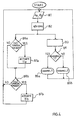
- Figure 4 is a flow diagram illustrating operation of the processing unit 1.
- the transducers 7a, 7b detect in real time and in a continuous manner the state of wear of the pads of the brakes with which they are associated, for example by means of the relative position between caliper body and pad during braking.
- the signals produced by the transducers are supplied to the inputs 3a, 3b of the microprocessor 2 in the form of analog signals 4a, 4b (step B1).
- the signals 4a, 4b are also directly sent, via the respective outputs 8a, 8b, to a telemetric detection device which may, for example, provide a graphic representation thereof, as for example shown in Figure 5, in which the two graphs A and B illustrate the evolution, over time (in terms of the number of times a circuit is travelled around), of the signals 4a, 4b and provide an indication as to the wear (in mm) of the pads of a brake on the left-hand side (A) and on the right-hand side (B) of the vehicle.
- a telemetric detection device which may, for example, provide a graphic representation thereof, as for example shown in Figure 5, in which the two graphs A and B illustrate the evolution, over time (in terms of the number of times a circuit is travelled around), of the signals 4a, 4b and provide an indication as to the wear (in mm) of the pads of a brake on the left-hand side (A) and on the right-hand side (B) of the vehicle.
- the microprocessor 2 after sampling and quantifying the analog signals 4a, 4b in order to convert them into digital form (step B2), carries out processing of them designed firstly to allow a representation of the state of wear of -the pads in numerical format on the display device (step B3). Therefore when the channel to be displayed has been determined (step B4), the corresponding data is displayed on the display 10 (steps B5a, B5b). The choice of the channel to be displayed is performed by the driver who operates the channel selector 12. At the same time the microprocessor 2 performs a comparison of the wear value corresponding to the value of the signal 4a, 4b sampled and quantified (step B6a, B6b) in order to verify whether the previously set alarm threshold has been exceeded.
- the microprocessor 2 will activate the signalling device 11a, 11b corresponding to the channel for which the threshold value has been exceeded (for example, in the case of a dual-coloured LED, the colour will change from green to red), indicating to the user that the threshold has been exceeded (steps B7a, B7b).
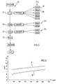
- Figure 6 shows a plan view of a disc brake, in particular for high-performance vehicles such as racing cars equipped with a particularly advantageous transducer and particularly suitable for use with the apparatus according to the present invention.
- a caliper body 50 straddling a respective disc 51 supports in respective seats two opposing pads 52, 53, each of which is composed in a known manner of a lining 54 which faces the disc 51 and consists of material with a high coefficient of friction and is supported by a plate 55.
- three hydraulic cylinder/piston groups 56a-58a, 56b-58b which can be activated so as to thrust the respective pad 52, 53 against the disc 51, are formed in both sides of the caliper body 50 with respect the disc 51.
- the radiator 59a, 61a, 59b, 61b of the pistons at the ends is provided with holes.
- the radiator 60a, 60b of the central pistons has a circumferential groove 62.
- One of the two central pistons in the example the one on the inner side of the caliper body 50, has associated with it a relative position transducer 63, of the contact type and in particular of the type known as LVDT, with a fixed part attached to the caliper body and inserted by means of screwing into a hole 64 passing alongside the cylinder/piston 57a.
- a fork member 65 is mounted on the free end of the movable element of the transducer 63. The fork member 65 engages with the groove 62 on the radiator 60a of the piston.
- the plates 55 of the pads 52, 53 are constantly in contact with the radiators of the pistons.
- the pistons 56a-58a and 56b-58b are axially extended with respect to the caliper body 50 by a given amount.
- the position of the piston 57a with respect to the caliper body 50 is converted by the transducer 63 into an electrical signal.
- the piston 57a is actuated and moves forward in the direction of the arrow shown in Figure 8, so as to bias, together with the other pistons 56a and 58a, the pad 52 against the surface of the disc 51; at the same time, the pistons 56b-58b are activated so as to bias the opposite pad 53 against the disc 51.
- the linings of the pads are subject to wear and their thickness decreases.
- the piston 57a, together with the pistons 56a, 58a, 56b-58b retracts, but does not return into the rest position prior to braking, remaining more extended with respect to the position prior to braking by an amount corresponding to the reduced thickness of the pad linings.
- the axial variation in position of the piston 57a with respect to the caliper body results in a corresponding variation in extension of the movable element of the transducer 63 and hence in a variation in the electrical signal converted.
- the processing unit 2 is thus able to determine the variation in relative position of the piston with respect to the caliper body before and after braking and hence the degree of wear of the pad. In this way the transducer 63 provides an indication in real time as to the degree of wear of the pads.
- the apparatus according to the present invention has the advantage of monitoring and providing the driver of the vehicle, continuously and in real time during travel, with information regarding the state of wear of the brake pads of the vehicle. This is of particular importance in specific applications, for example during racing, where braking is always or nearly always performed in extreme conditions, since the driver will be constantly informed of the conditions of the braking system.
- the apparatus according to the invention may be used with transducers of various types, provided that they provide an electrical signal in real time indicating the state of wear of the pad.
- the particular type of transducer described above owing to the manner in which it is associated with the brake, detects the travel of the piston actuating the pad during braking and thus provides a substantially direct measurement of the degree of wear of the pad.
- This transducer although it is particularly suitable for use with the apparatus according to the invention, may therefore be applied also to apparatuses of different types, whenever it is required to obtain a substantially direct measurement of the degree of wear of the pad.
- transducer 63 may also be applied to different disc brakes, with a single cylinder/piston group for each pad.
- the number of measuring channels of the apparatus according to the invention may vary depending on the application. For example, it is possible to have two channels, with a transducer associated with one of the brake pads of a front wheel and a second transducer associated with one of the brake pads of one of the rear wheels. Alternatively, for a more complete measurement, it is possible to have four channels, with transducers associated with one of the calipers of each wheel. For an even more complete check as to the state of wear of all the pads of the braking system, it is possible to have two transducers for each brake, associated with the two opposing pads thereof.
Landscapes
- Engineering & Computer Science (AREA)
- General Engineering & Computer Science (AREA)
- Mechanical Engineering (AREA)
- Braking Arrangements (AREA)
- Valves And Accessory Devices For Braking Systems (AREA)
Abstract
Description
Claims (18)
- On-board apparatus for monitoring the degree of wear of pads of vehicle disc brakes in general, characterized in that it comprises:transducer means designed to detect in real time the current degree of wear of at least one pad and generate a respective electrical signal depending on the current degree of wear;on-board electronic processing means designed to receive said electrical signal and process it so as to obtain a measurement of the current degree of wear;on-board display means controlled by the processing means and designed to provide the vehicle driver in real time with said measurement of the current degree of wear.
- Apparatus according to Claim 1, characterized in that said processing means comprise a programmable processing unit.
- Apparatus according to Claim 1 or 2, characterized in that said display means comprise an alphanumeric display device controlled by said programmable processing unit.
- Apparatus according to Claim 1, 2 or 3, characterized in that it comprises at least one on-board alarm signalling device and in that said electronic processing means -perform a comparison between said measurement of the current degree of wear and a preset safety value, activating said alarm signalling device in the event of said safety value being exceeded.
- Apparatus according to any one of the preceding claims, characterized in that said programmable processing unit comprises an input port for connection to a remote programming device.
- Apparatus according to any one of the preceding claims, characterized in that said transducer means are relative position transducer means which are sensitive to the relative displacement of the pad with respect to the caliper body during braking.
- Apparatus according to Claim 6, characterized in that said transducer means are of the contact type, in particular comprising an LVDT transducer which is attached to a caliper body of the brake, with a movable element displaced by a piston for actuation of the pad, so as to be able to detect the relative position of the piston with respect to the caliper body.
- Apparatus according to Claim 7, characterized in that said movable element of the transducer is provided with an engaging element which engages with a respective seat in a radiator of said actuating piston.
- Apparatus according to Claim 8, characterized in that said engaging element is a fork member which is fixed substantially to a free end of the movable part, and said seat is a groove in said radiator.
- Apparatus according to Claim 9, characterized in that it comprises circuitry means for conditioning the signal generated by said transducer.
- Apparatus according to any one of the preceding claims, characterized in that it comprises a plurality of channels for a respective plurality of transducer means, each of said transducer means being associated with a respective pad of one of more brakes of the vehicle braking system.
- Device for detecting the degree of wear of a pad of a vehicle disc brake, characterized in that it comprises a relative position transducer having a fixed body attached to a caliper body of the brake and a movable element which is displaced by a piston for actuating, during braking, the pad, so as to be able to detect the relative position of the piston with respect to the caliper body.
- Device according to Claim 12, characterized in that said relative position transducer is of the LVDT type.
- Device according to Claim 12 or 13, characterized in that said movable element is provided with engaging means which engage in a respective seat formed in a radiator of said piston.
- Device according to Claim 14, characterized in that said engaging means comprise a fork member fixed substantially to a free end of the movable element and said seat comprises a groove formed in said radiator.
- Device according to Claim 15, characterized in that said transducer is housed in a seat formed in said caliper body alongside said piston.
- Method for monitoring the degree of wear of pads of vehicle brakes in general, characterized in that it envisages generating an electrical signal depending on the current degree of wear of a respective pad, processing of said electrical signal so as to obtain a measurement of the current degree of wear, and displaying, in real time, to the driver on board the vehicle said measurement of the current degree of wear.
- Method according to Claim 17, characterized in that it also envisages a comparison of said measurement with a preset safety value and, in the case of the safety value being exceeded, signalling of an alarm to the driver.
Priority Applications (3)
| Application Number | Priority Date | Filing Date | Title |
|---|---|---|---|
| EP99830444A EP1069336B1 (en) | 1999-07-14 | 1999-07-14 | On-board apparatus for monitoring in real time the wear of vehicle brakes |
| DE69935508T DE69935508T2 (en) | 1999-07-14 | 1999-07-14 | Device for displaying vehicle brake wear in real time |
| AT99830444T ATE356944T1 (en) | 1999-07-14 | 1999-07-14 | DEVICE FOR DISPLAYING VEHICLE BRAKE WEAR IN REAL TIME |
Applications Claiming Priority (1)
| Application Number | Priority Date | Filing Date | Title |
|---|---|---|---|
| EP99830444A EP1069336B1 (en) | 1999-07-14 | 1999-07-14 | On-board apparatus for monitoring in real time the wear of vehicle brakes |
Publications (2)
| Publication Number | Publication Date |
|---|---|
| EP1069336A1 true EP1069336A1 (en) | 2001-01-17 |
| EP1069336B1 EP1069336B1 (en) | 2007-03-14 |
Family
ID=8243499
Family Applications (1)
| Application Number | Title | Priority Date | Filing Date |
|---|---|---|---|
| EP99830444A Expired - Lifetime EP1069336B1 (en) | 1999-07-14 | 1999-07-14 | On-board apparatus for monitoring in real time the wear of vehicle brakes |
Country Status (3)
| Country | Link |
|---|---|
| EP (1) | EP1069336B1 (en) |
| AT (1) | ATE356944T1 (en) |
| DE (1) | DE69935508T2 (en) |
Cited By (5)
| Publication number | Priority date | Publication date | Assignee | Title |
|---|---|---|---|---|
| FR2835896A1 (en) | 2002-02-12 | 2003-08-15 | Delphi Tech Inc | Sensor for brake pad to rotor contact for motor vehicle, has contact on brake pad to complete electrical circuit on contact with brake rotor |
| FR2959717A1 (en) * | 2010-05-05 | 2011-11-11 | Peugeot Citroen Automobiles Sa | Continuous brake disk damage state monitoring device for braking device of vehicle i.e. motor vehicle, has alarm module that scans accessible memory to start alarm when accumulation of damage rates reaches given threshold |
| WO2011113553A3 (en) * | 2010-03-17 | 2011-11-17 | Haldex Brake Products Ab | Sensor unit for a disk brake |
| CN112135984A (en) * | 2018-05-17 | 2020-12-25 | 意大利Itt有限责任公司 | vehicle braking system |
| WO2024194039A1 (en) * | 2023-03-23 | 2024-09-26 | Zf Cv Systems Europe Bv | Wear sensor for a vehicle, and controller for the wear sensor, and method for indicating a state of wear of a component of the vehicle |
Citations (6)
| Publication number | Priority date | Publication date | Assignee | Title |
|---|---|---|---|---|
| US3808593A (en) * | 1971-05-13 | 1974-04-30 | Bosch Gmbh Robert | Brake arrangement or the like provided with an electromechanical wear-monitoring transducer |
| DE3348387C2 (en) * | 1983-01-08 | 1993-01-28 | Robert Bosch Gmbh, 7000 Stuttgart, De | Vehicle brakes testing system |
| DE4212279A1 (en) * | 1992-04-11 | 1993-10-14 | Hella Kg Hueck & Co | Wear monitor for disc brake pad esp. on motor vehicle - provides continuous linear indication of stroke of brake piston until alarm is given at critical deg. of abrasion |
| WO1997035122A1 (en) * | 1996-03-19 | 1997-09-25 | Komatsu Ltd. | Device for detecting abrasion of brake for vehicle |
| US5848672A (en) * | 1994-06-08 | 1998-12-15 | Lucas Industries Public Limited Company | Brake lining wear sensing system |
| DE19738317A1 (en) * | 1997-09-02 | 1999-03-18 | Itt Mfg Enterprises Inc | Sensor for continuous determination of wear of motor vehicle brake linings |
-
1999
- 1999-07-14 AT AT99830444T patent/ATE356944T1/en not_active IP Right Cessation
- 1999-07-14 EP EP99830444A patent/EP1069336B1/en not_active Expired - Lifetime
- 1999-07-14 DE DE69935508T patent/DE69935508T2/en not_active Expired - Lifetime
Patent Citations (6)
| Publication number | Priority date | Publication date | Assignee | Title |
|---|---|---|---|---|
| US3808593A (en) * | 1971-05-13 | 1974-04-30 | Bosch Gmbh Robert | Brake arrangement or the like provided with an electromechanical wear-monitoring transducer |
| DE3348387C2 (en) * | 1983-01-08 | 1993-01-28 | Robert Bosch Gmbh, 7000 Stuttgart, De | Vehicle brakes testing system |
| DE4212279A1 (en) * | 1992-04-11 | 1993-10-14 | Hella Kg Hueck & Co | Wear monitor for disc brake pad esp. on motor vehicle - provides continuous linear indication of stroke of brake piston until alarm is given at critical deg. of abrasion |
| US5848672A (en) * | 1994-06-08 | 1998-12-15 | Lucas Industries Public Limited Company | Brake lining wear sensing system |
| WO1997035122A1 (en) * | 1996-03-19 | 1997-09-25 | Komatsu Ltd. | Device for detecting abrasion of brake for vehicle |
| DE19738317A1 (en) * | 1997-09-02 | 1999-03-18 | Itt Mfg Enterprises Inc | Sensor for continuous determination of wear of motor vehicle brake linings |
Cited By (10)
| Publication number | Priority date | Publication date | Assignee | Title |
|---|---|---|---|---|
| FR2835896A1 (en) | 2002-02-12 | 2003-08-15 | Delphi Tech Inc | Sensor for brake pad to rotor contact for motor vehicle, has contact on brake pad to complete electrical circuit on contact with brake rotor |
| WO2011113553A3 (en) * | 2010-03-17 | 2011-11-17 | Haldex Brake Products Ab | Sensor unit for a disk brake |
| CN102803780A (en) * | 2010-03-17 | 2012-11-28 | 瀚德刹车片产品公司 | Sensor unit for a disk brake |
| US20130068571A1 (en) * | 2010-03-17 | 2013-03-21 | Hans Welin | Sensor Unit For A Disc Brake |
| US9168905B2 (en) * | 2010-03-17 | 2015-10-27 | Haldex Brake Products Ab | Sensor unit for a disc brake |
| CN102803780B (en) * | 2010-03-17 | 2016-01-20 | 瀚德刹车片产品公司 | For the sensor unit of disk type braker |
| FR2959717A1 (en) * | 2010-05-05 | 2011-11-11 | Peugeot Citroen Automobiles Sa | Continuous brake disk damage state monitoring device for braking device of vehicle i.e. motor vehicle, has alarm module that scans accessible memory to start alarm when accumulation of damage rates reaches given threshold |
| CN112135984A (en) * | 2018-05-17 | 2020-12-25 | 意大利Itt有限责任公司 | vehicle braking system |
| CN112135984B (en) * | 2018-05-17 | 2023-03-28 | 意大利Itt有限责任公司 | Vehicle brake system |
| WO2024194039A1 (en) * | 2023-03-23 | 2024-09-26 | Zf Cv Systems Europe Bv | Wear sensor for a vehicle, and controller for the wear sensor, and method for indicating a state of wear of a component of the vehicle |
Also Published As
| Publication number | Publication date |
|---|---|
| DE69935508T2 (en) | 2007-12-13 |
| EP1069336B1 (en) | 2007-03-14 |
| ATE356944T1 (en) | 2007-04-15 |
| DE69935508D1 (en) | 2007-04-26 |
Similar Documents
| Publication | Publication Date | Title |
|---|---|---|
| EP0758962B1 (en) | Vehicle brake monitoring system | |
| US5848672A (en) | Brake lining wear sensing system | |
| DE3407716C2 (en) | ||
| US6411206B1 (en) | Brake monitoring system | |
| KR100478308B1 (en) | Mechanically adjustable wear indicator | |
| US5651430A (en) | Disc brake assembly | |
| US11137042B2 (en) | Wear monitoring device and disk brake having a wear monitoring device | |
| JP7182844B2 (en) | Method and system for analyzing wear behavior of brake pads | |
| EP1069336B1 (en) | On-board apparatus for monitoring in real time the wear of vehicle brakes | |
| US6250430B1 (en) | System and method for determining brake lining wear using a temperature detector and a brake actuation system | |
| US6308803B1 (en) | Brake-disk with visual wear control means | |
| CN109844479A (en) | Threaded Fastener Load Monitoring System | |
| US9103394B2 (en) | Heavy duty brake drum wear indicator | |
| US20060254868A1 (en) | Motor vehicle brake system | |
| JP2975314B2 (en) | Wear plate | |
| JP2021032278A (en) | Brake state monitoring device and brake state monitoring method | |
| US20040168864A1 (en) | Braking lining wear system | |
| US7370733B2 (en) | Disc brake friction couple wear indicator | |
| KR20070066000A (en) | Wear detection device of brake disc | |
| JP2023050931A (en) | Friction member and friction member sensor system using the same | |
| WO2005090821A1 (en) | Sensing system for a disc brake | |
| CN104114896A (en) | Integral brake surface wear indicator | |
| JP2002130349A (en) | Brake pad | |
| KR940002106Y1 (en) | Brake linning | |
| CN113263870A (en) | Tire wear indication system and tire using the same |
Legal Events
| Date | Code | Title | Description |
|---|---|---|---|
| PUAI | Public reference made under article 153(3) epc to a published international application that has entered the european phase |
Free format text: ORIGINAL CODE: 0009012 |
|
| AK | Designated contracting states |
Kind code of ref document: A1 Designated state(s): AT BE CH CY DE DK ES FI FR GB GR IE IT LI LU MC NL PT SE |
|
| AX | Request for extension of the european patent |
Free format text: AL;LT;LV;MK;RO;SI |
|
| 17P | Request for examination filed |
Effective date: 20010525 |
|
| AKX | Designation fees paid |
Free format text: AT BE CH CY DE DK ES FI FR GB GR IE IT LI LU MC NL PT SE |
|
| 17Q | First examination report despatched |
Effective date: 20040827 |
|
| GRAP | Despatch of communication of intention to grant a patent |
Free format text: ORIGINAL CODE: EPIDOSNIGR1 |
|
| GRAS | Grant fee paid |
Free format text: ORIGINAL CODE: EPIDOSNIGR3 |
|
| GRAA | (expected) grant |
Free format text: ORIGINAL CODE: 0009210 |
|
| AK | Designated contracting states |
Kind code of ref document: B1 Designated state(s): AT BE CH CY DE DK ES FI FR GB GR IE IT LI LU MC NL PT SE |
|
| PG25 | Lapsed in a contracting state [announced via postgrant information from national office to epo] |
Ref country code: NL Free format text: LAPSE BECAUSE OF FAILURE TO SUBMIT A TRANSLATION OF THE DESCRIPTION OR TO PAY THE FEE WITHIN THE PRESCRIBED TIME-LIMIT Effective date: 20070314 Ref country code: LI Free format text: LAPSE BECAUSE OF FAILURE TO SUBMIT A TRANSLATION OF THE DESCRIPTION OR TO PAY THE FEE WITHIN THE PRESCRIBED TIME-LIMIT Effective date: 20070314 Ref country code: FI Free format text: LAPSE BECAUSE OF FAILURE TO SUBMIT A TRANSLATION OF THE DESCRIPTION OR TO PAY THE FEE WITHIN THE PRESCRIBED TIME-LIMIT Effective date: 20070314 Ref country code: CH Free format text: LAPSE BECAUSE OF FAILURE TO SUBMIT A TRANSLATION OF THE DESCRIPTION OR TO PAY THE FEE WITHIN THE PRESCRIBED TIME-LIMIT Effective date: 20070314 Ref country code: BE Free format text: LAPSE BECAUSE OF FAILURE TO SUBMIT A TRANSLATION OF THE DESCRIPTION OR TO PAY THE FEE WITHIN THE PRESCRIBED TIME-LIMIT Effective date: 20070314 Ref country code: AT Free format text: LAPSE BECAUSE OF FAILURE TO SUBMIT A TRANSLATION OF THE DESCRIPTION OR TO PAY THE FEE WITHIN THE PRESCRIBED TIME-LIMIT Effective date: 20070314 |
|
| REG | Reference to a national code |
Ref country code: GB Ref legal event code: FG4D |
|
| REG | Reference to a national code |
Ref country code: CH Ref legal event code: EP |
|
| REF | Corresponds to: |
Ref document number: 69935508 Country of ref document: DE Date of ref document: 20070426 Kind code of ref document: P |
|
| REG | Reference to a national code |
Ref country code: IE Ref legal event code: FG4D |
|
| RIN2 | Information on inventor provided after grant (corrected) |
Inventor name: ZONCA, GIANLUCA Inventor name: BONALUMI, ALFIO |
|
| PG25 | Lapsed in a contracting state [announced via postgrant information from national office to epo] |
Ref country code: SE Free format text: LAPSE BECAUSE OF FAILURE TO SUBMIT A TRANSLATION OF THE DESCRIPTION OR TO PAY THE FEE WITHIN THE PRESCRIBED TIME-LIMIT Effective date: 20070614 |
|
| PG25 | Lapsed in a contracting state [announced via postgrant information from national office to epo] |
Ref country code: ES Free format text: LAPSE BECAUSE OF FAILURE TO SUBMIT A TRANSLATION OF THE DESCRIPTION OR TO PAY THE FEE WITHIN THE PRESCRIBED TIME-LIMIT Effective date: 20070625 |
|
| PG25 | Lapsed in a contracting state [announced via postgrant information from national office to epo] |
Ref country code: PT Free format text: LAPSE BECAUSE OF FAILURE TO SUBMIT A TRANSLATION OF THE DESCRIPTION OR TO PAY THE FEE WITHIN THE PRESCRIBED TIME-LIMIT Effective date: 20070814 |
|
| NLV1 | Nl: lapsed or annulled due to failure to fulfill the requirements of art. 29p and 29m of the patents act | ||
| REG | Reference to a national code |
Ref country code: CH Ref legal event code: PL |
|
| EN | Fr: translation not filed | ||
| EN | Fr: translation not filed | ||
| PLBE | No opposition filed within time limit |
Free format text: ORIGINAL CODE: 0009261 |
|
| STAA | Information on the status of an ep patent application or granted ep patent |
Free format text: STATUS: NO OPPOSITION FILED WITHIN TIME LIMIT |
|
| PG25 | Lapsed in a contracting state [announced via postgrant information from national office to epo] |
Ref country code: DK Free format text: LAPSE BECAUSE OF FAILURE TO SUBMIT A TRANSLATION OF THE DESCRIPTION OR TO PAY THE FEE WITHIN THE PRESCRIBED TIME-LIMIT Effective date: 20070314 |
|
| 26N | No opposition filed |
Effective date: 20071217 |
|
| PG25 | Lapsed in a contracting state [announced via postgrant information from national office to epo] |
Ref country code: MC Free format text: LAPSE BECAUSE OF NON-PAYMENT OF DUE FEES Effective date: 20070731 Ref country code: GR Free format text: LAPSE BECAUSE OF FAILURE TO SUBMIT A TRANSLATION OF THE DESCRIPTION OR TO PAY THE FEE WITHIN THE PRESCRIBED TIME-LIMIT Effective date: 20070615 Ref country code: FR Free format text: LAPSE BECAUSE OF FAILURE TO SUBMIT A TRANSLATION OF THE DESCRIPTION OR TO PAY THE FEE WITHIN THE PRESCRIBED TIME-LIMIT Effective date: 20071102 |
|
| PG25 | Lapsed in a contracting state [announced via postgrant information from national office to epo] |
Ref country code: IE Free format text: LAPSE BECAUSE OF NON-PAYMENT OF DUE FEES Effective date: 20070716 |
|
| PG25 | Lapsed in a contracting state [announced via postgrant information from national office to epo] |
Ref country code: FR Free format text: LAPSE BECAUSE OF FAILURE TO SUBMIT A TRANSLATION OF THE DESCRIPTION OR TO PAY THE FEE WITHIN THE PRESCRIBED TIME-LIMIT Effective date: 20070314 |
|
| PG25 | Lapsed in a contracting state [announced via postgrant information from national office to epo] |
Ref country code: CY Free format text: LAPSE BECAUSE OF FAILURE TO SUBMIT A TRANSLATION OF THE DESCRIPTION OR TO PAY THE FEE WITHIN THE PRESCRIBED TIME-LIMIT Effective date: 20070314 |
|
| PG25 | Lapsed in a contracting state [announced via postgrant information from national office to epo] |
Ref country code: LU Free format text: LAPSE BECAUSE OF NON-PAYMENT OF DUE FEES Effective date: 20070714 |
|
| PGFP | Annual fee paid to national office [announced via postgrant information from national office to epo] |
Ref country code: GB Payment date: 20120719 Year of fee payment: 14 |
|
| PGFP | Annual fee paid to national office [announced via postgrant information from national office to epo] |
Ref country code: IT Payment date: 20120716 Year of fee payment: 14 |
|
| PGFP | Annual fee paid to national office [announced via postgrant information from national office to epo] |
Ref country code: DE Payment date: 20121001 Year of fee payment: 14 |
|
| GBPC | Gb: european patent ceased through non-payment of renewal fee |
Effective date: 20130714 |
|
| PG25 | Lapsed in a contracting state [announced via postgrant information from national office to epo] |
Ref country code: DE Free format text: LAPSE BECAUSE OF NON-PAYMENT OF DUE FEES Effective date: 20140201 Ref country code: GB Free format text: LAPSE BECAUSE OF NON-PAYMENT OF DUE FEES Effective date: 20130714 |
|
| REG | Reference to a national code |
Ref country code: DE Ref legal event code: R119 Ref document number: 69935508 Country of ref document: DE Effective date: 20140201 |
|
| PG25 | Lapsed in a contracting state [announced via postgrant information from national office to epo] |
Ref country code: IT Free format text: LAPSE BECAUSE OF NON-PAYMENT OF DUE FEES Effective date: 20130714 |