EP1069333A2 - Drum brake assembly - Google Patents
Drum brake assembly Download PDFInfo
- Publication number
- EP1069333A2 EP1069333A2 EP00203102A EP00203102A EP1069333A2 EP 1069333 A2 EP1069333 A2 EP 1069333A2 EP 00203102 A EP00203102 A EP 00203102A EP 00203102 A EP00203102 A EP 00203102A EP 1069333 A2 EP1069333 A2 EP 1069333A2
- Authority
- EP
- European Patent Office
- Prior art keywords
- shoe
- brake
- drum
- web
- curvature
- Prior art date
- Legal status (The legal status is an assumption and is not a legal conclusion. Google has not performed a legal analysis and makes no representation as to the accuracy of the status listed.)
- Granted
Links
Images


Classifications
-
- F—MECHANICAL ENGINEERING; LIGHTING; HEATING; WEAPONS; BLASTING
- F16—ENGINEERING ELEMENTS AND UNITS; GENERAL MEASURES FOR PRODUCING AND MAINTAINING EFFECTIVE FUNCTIONING OF MACHINES OR INSTALLATIONS; THERMAL INSULATION IN GENERAL
- F16D—COUPLINGS FOR TRANSMITTING ROTATION; CLUTCHES; BRAKES
- F16D65/00—Parts or details
- F16D65/02—Braking members; Mounting thereof
- F16D65/04—Bands, shoes or pads; Pivots or supporting members therefor
- F16D65/08—Bands, shoes or pads; Pivots or supporting members therefor for internally-engaging brakes
-
- F—MECHANICAL ENGINEERING; LIGHTING; HEATING; WEAPONS; BLASTING
- F16—ENGINEERING ELEMENTS AND UNITS; GENERAL MEASURES FOR PRODUCING AND MAINTAINING EFFECTIVE FUNCTIONING OF MACHINES OR INSTALLATIONS; THERMAL INSULATION IN GENERAL
- F16D—COUPLINGS FOR TRANSMITTING ROTATION; CLUTCHES; BRAKES
- F16D49/00—Brakes with a braking member co-operating with the periphery of a drum, wheel-rim, or the like
- F16D49/18—Brakes with three or more brake-blocks
-
- B—PERFORMING OPERATIONS; TRANSPORTING
- B23—MACHINE TOOLS; METAL-WORKING NOT OTHERWISE PROVIDED FOR
- B23P—METAL-WORKING NOT OTHERWISE PROVIDED FOR; COMBINED OPERATIONS; UNIVERSAL MACHINE TOOLS
- B23P15/00—Making specific metal objects by operations not covered by a single other subclass or a group in this subclass
- B23P15/18—Making specific metal objects by operations not covered by a single other subclass or a group in this subclass brake shoes
-
- B—PERFORMING OPERATIONS; TRANSPORTING
- B23—MACHINE TOOLS; METAL-WORKING NOT OTHERWISE PROVIDED FOR
- B23P—METAL-WORKING NOT OTHERWISE PROVIDED FOR; COMBINED OPERATIONS; UNIVERSAL MACHINE TOOLS
- B23P25/00—Auxiliary treatment of workpieces, before or during machining operations, to facilitate the action of the tool or the attainment of a desired final condition of the work, e.g. relief of internal stress
-
- B—PERFORMING OPERATIONS; TRANSPORTING
- B24—GRINDING; POLISHING
- B24B—MACHINES, DEVICES, OR PROCESSES FOR GRINDING OR POLISHING; DRESSING OR CONDITIONING OF ABRADING SURFACES; FEEDING OF GRINDING, POLISHING, OR LAPPING AGENTS
- B24B19/00—Single-purpose machines or devices for particular grinding operations not covered by any other main group
- B24B19/26—Single-purpose machines or devices for particular grinding operations not covered by any other main group for grinding workpieces with arcuate surfaces, e.g. parts of car bodies, bumpers or magnetic recording heads
- B24B19/28—Single-purpose machines or devices for particular grinding operations not covered by any other main group for grinding workpieces with arcuate surfaces, e.g. parts of car bodies, bumpers or magnetic recording heads for grinding shoes or linings of drum brakes
-
- F—MECHANICAL ENGINEERING; LIGHTING; HEATING; WEAPONS; BLASTING
- F16—ENGINEERING ELEMENTS AND UNITS; GENERAL MEASURES FOR PRODUCING AND MAINTAINING EFFECTIVE FUNCTIONING OF MACHINES OR INSTALLATIONS; THERMAL INSULATION IN GENERAL
- F16D—COUPLINGS FOR TRANSMITTING ROTATION; CLUTCHES; BRAKES
- F16D51/00—Brakes with outwardly-movable braking members co-operating with the inner surface of a drum or the like
- F16D51/02—Brakes with outwardly-movable braking members co-operating with the inner surface of a drum or the like shaped as one or more circumferential band
- F16D51/04—Brakes with outwardly-movable braking members co-operating with the inner surface of a drum or the like shaped as one or more circumferential band mechanically actuated
-
- F—MECHANICAL ENGINEERING; LIGHTING; HEATING; WEAPONS; BLASTING
- F16—ENGINEERING ELEMENTS AND UNITS; GENERAL MEASURES FOR PRODUCING AND MAINTAINING EFFECTIVE FUNCTIONING OF MACHINES OR INSTALLATIONS; THERMAL INSULATION IN GENERAL
- F16D—COUPLINGS FOR TRANSMITTING ROTATION; CLUTCHES; BRAKES
- F16D2121/00—Type of actuator operation force
- F16D2121/14—Mechanical
-
- F—MECHANICAL ENGINEERING; LIGHTING; HEATING; WEAPONS; BLASTING
- F16—ENGINEERING ELEMENTS AND UNITS; GENERAL MEASURES FOR PRODUCING AND MAINTAINING EFFECTIVE FUNCTIONING OF MACHINES OR INSTALLATIONS; THERMAL INSULATION IN GENERAL
- F16D—COUPLINGS FOR TRANSMITTING ROTATION; CLUTCHES; BRAKES
- F16D2125/00—Components of actuators
- F16D2125/18—Mechanical mechanisms
- F16D2125/58—Mechanical mechanisms transmitting linear movement
- F16D2125/68—Lever-link mechanisms, e.g. toggles with change of force ratio
-
- F—MECHANICAL ENGINEERING; LIGHTING; HEATING; WEAPONS; BLASTING
- F16—ENGINEERING ELEMENTS AND UNITS; GENERAL MEASURES FOR PRODUCING AND MAINTAINING EFFECTIVE FUNCTIONING OF MACHINES OR INSTALLATIONS; THERMAL INSULATION IN GENERAL
- F16D—COUPLINGS FOR TRANSMITTING ROTATION; CLUTCHES; BRAKES
- F16D2250/00—Manufacturing; Assembly
- F16D2250/003—Chip removing
-
- F—MECHANICAL ENGINEERING; LIGHTING; HEATING; WEAPONS; BLASTING
- F16—ENGINEERING ELEMENTS AND UNITS; GENERAL MEASURES FOR PRODUCING AND MAINTAINING EFFECTIVE FUNCTIONING OF MACHINES OR INSTALLATIONS; THERMAL INSULATION IN GENERAL
- F16D—COUPLINGS FOR TRANSMITTING ROTATION; CLUTCHES; BRAKES
- F16D2250/00—Manufacturing; Assembly
- F16D2250/0092—Tools or machines for producing linings
Definitions
- This invention relates to a drum brake assembly and more particularly to a drum brake assembly having a particular configuration of brake shoe.
- the invention will be described with particular reference to a drum brake assembly for use in conjunction with a disc brake, but it is to be understood that the invention has a wider application.
- Drum brakes are known to have certain advantages over disc brakes, particularly in park brake applications. Those advantages include superior braking force in some situations, and, where used as a park brake, the continued application of braking force where temperature variations occur whilst the brake is on. It has been found, for example, with certain disc type park brake assemblies, that where the temperature falls after the park brake has been applied, contraction of the brake components as a consequence of the temperature fall and a reduction of coefficient of friction with temperature fall will cause a relaxation of the braking force and possibly result in a vehicle run away.
- drum brake assemblies are of complex construction and assembly, and are generally comprised of a large number of components and parts.
- a typical prior art drum type park brake assembly uses a total of 31 separate parts per wheel, of which there are 18 different components. Such a large number of parts results in the park brake assembly being expensive and time consuming to assemble and fix to a vehicle.
- drum type park brake assemblies when used in conjunction with disc brake assemblies is that the park brake is generally only used after the vehicle has been brought to a stop by the disc brake.
- the drum shoe friction linings do not become properly bedded by wearing against the inner surface of the drum as in the case where the drum brake serves the function of both service and park brakes. Unless there is a near perfect match between the diameters of the lining when the brake is applied and the drum the shoe will not properly contact the drum over its entire surface and an inferior braking force will result.
- An object of this invention is to provide a drum brake which is simpler than prior art brakes, but is no less effective than prior art brakes.
- a further object of the invention is to provide a single shoe drum brake which is capable of providing an effective braking force without requiring in-situ bedding.
- a yet further object of the invention is to provide a single shoe drum brake which can operate without return springs.
- a further object is to provide a method of manufacturing a brake member of a single shoe drum brake.
- a drum brake assembly comprising a drum rotatable on an axis and having a radially inner surface, a support, a brake member mounted on said support and being movable relative thereto, said brake member including a high strength resilient shoe of substantially circular form having a radially outer face and at least one friction lining mounted thereto on said outer face and extending around said circular form, and actuating means which, when actuated, causes said brake member to diametrically expand such that said lining contacts said drum inner surface and thereby provides a braking action to said drum, said shoe being of substantially constant cross-sectional form along at least a major portion of its length, said cross-sectional form and the material from which said shoe is made being such that said shoe provides significant support for said lining along the entire length of said lining, the resilience of said shoe being such that when said actuating means is released said shoe diametrically contracts to move said lining out of contact with said drum inner surface.
- the invention extends to a method of manufacturing a brake member
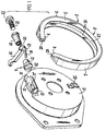
- a park brake assembly as shown in Figures 1 and 2 of the drawings includes a brake member 2 which has been formed as a substantially closed circle, but with a gap being defined between the ends 4 of the brake member.
- the brake member 2 is comprised of a shoe 5 and a pair of friction linings 6 and 7 adhered or otherwise fixed in known manner to the radially outer face 8 of the shoe 5.
- the friction linings 6 and 7 will be made of conventional material as will be known by one skilled in the art, and the shoe 5 will be formed of a resilient material such as, but not limited to, mild steel, composite materials, high strength plastics, and sintered metals.
- the mechanism 9 includes a tubular sleeve 10 which is fixed to a plate like support 11 which serves to provide structure for the brake assembly and also serves as a dust cover for a disc brake assembly (not shown).
- the sleeve 10 thus serves as an abutment for the brake member 2.
- a tappet 12 locates in one end 13 of the sleeve 10, and an adjusting nut 14 locates in the other end 15 of the sleeve 10.
- An actuating lever 16 locates between the tappet 12 and the adjusting nut 14 and passes out of the sleeve 10 through an opening 17 in the back face thereof.
- a push rod 18 fits into a blind bore 19 in one end of the lever 16, and presses against the tappet 12.
- a knuckle 20 on the opposite side of the lever locates in a recess in the adjusting nut 14.
- An adjusting screw 21 screws into the adjusting nut 14 to provide a facility for varying the effective length of the mechanism 9.
- the tappet 12 and screw 21 each have a groove 22 therein in which the ends 4 of the brake member 2 locate. The lever 16 thus operates in use to urge the ends 4 of the brake member 2 apart into contact with the radially inner surface 24 of a drum 23 shown in Figure 2.
- the cross-section shape of the shoe 5 can be of any suitable form although it is important that the shoe is able to properly support the linings 6,7 around the entire circumference of the brake member 2. This differs from prior art band brake type arrangements in which the circumferential band is very flexible in a radial direction and does not adequately support the lining. The radial forces on the lining during braking can be very high and if the shoe distorts inwardly to even a small extent a significant area of the lining will no longer provide an adequate braking force.
- the shoe 5 is resiliently flexible. This differs from some prior art arrangements, such as two shoe drum brakes, where the shoe or shoes are substantially rigid. These prior art shoes require either a plurality of actuators to operate or are pivotable relative to their abutments, and require spring retractors, and are accordingly. It is this complicated requiring a large number of components to operate complicated multi-component type arrangement which the present invention seeks to improve on.
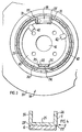
- the shoe 5 depicted in Figure 1, 2 and 4 is of channel cross-sectional shape comprising a web 25, and a pair of parallel flanges 26 which connect to and are preferably integral with the lateral edges 27 of the web 25 and project radially inwardly.
- the flanges 26 serve to increase the bending strength of the shoe and thereby resist radially inward deflection of the shoe under braking load.
- the dimensions of the flanges and web will be selected according to the particular application and anticipated loads. In one example application, which is considered suitable for a motor car park brake, the shoe 5 was made of mild steel, the flanges 26 had a length of 12.5mm and a thickness of 2.5mm, and the web was 25mm wide and had a thickness of 2.5mm.
- a mild steel shoe will have sufficient resilience to retract the linings 6,7 out of contact with the inner surface of the drum after the brake has been applied.
- a T-shaped shoe having the leg of the T-shape projecting radially inwardly to increase the bending strength of the shoe.
- the shoe has some resilience, for the configuration of the shoe is such that it acts as a spring in reducing the diameter of the shoe after the actuating mechanism 9 has been released.
- the spring force required can be derived from the sectional dimensions of the shoe 5.
- the shoe be made from high strength spring type material.
- the shoe may be made from a mild steel material which is relatively inexpensive but which will provide sufficient resilience for the brake to operate and retract. In some applications it may be advantageous to also include retracting springs.
- the diameter of the shoe 5 as manufactured will be smaller than the diameter of the shoe when assembled in the brake-off position.
- the diameter of the shoe 5 as manufactured will be smaller than the diameter of the shoe when assembled in the brake-off position.
- the shoe 5 has a substantially constant cross-sectional shape along its entire length. This is desirable because the manufacture of the shoe can then be effected by simply cutting individual shoes from a length of constant cross-section material of suitable dimensions, and then bending those cut lengths into their circular form. Clearly it will not then be necessary to fabricate the shoe from various parts as has heretofore been the norm. Where the radius of the shoe is small it may be necessary to treat the flange or flanges during the bending process to ensure that there is no crimping or bending of the flanges, but this would be a non-complicated manufacturing technique which could be rapidly carried out on a mass production line.
- the ends 4 of the shoe are preferably crimped into an M-shape as depicted at numeral 28 in Figure 1 to provide a suitable end formation which will fit into the grooves 22 in the actuating mechanism 9.
- the crimping of the ends 4 as shown will provide an effective yet simple method of forming the ends so that force transmitted by the actuating mechanism 9 will be transmitted to the shoe substantially along the longitudinal axis of the shoe. It will, however, be appreciated that it will be possible to provide contact points on the shoe which the actuating mechanism will engage which are spaced away from the ends 4.
- an abutment arm 30 is located midway between the ends 31 of the shoe 32 and can be compared with a conventional "leading-trailing" shoe arrangement.
- the flanges 33 of the shoe 32 may, for this purpose, each have a rectangular seat 34 cut out of them and the abutment arm may fit neatly into the seats so formed in order to provide an abutment point. End faces 35 at each end of the seat 34 contact the abutment arm 30.
- the shoe will be substantially free, pivoting relative to the abutment arm 30, as well as possessing the necessary resilience to retract the shoe from its brake-on condition.
- the actuating mechanism in this application is a hydraulic piston and cylinder assembly 36 and the ends 31 have been rounded to provide contact points which end faces 37 of the piston and cylinder assembly 36 engage.
- An adjuster mechanism (not shown) will also generally be included in the actuating mechanism.
- the shoe will be of uniform cross-section over substantially its entire length, but it is not essential that this be so. For example, in certain applications it may be desirable to have a reduced bending strength at a specific zone along the length of the shoe, and the shoe may have a reduced cross-section at that zone. However, for simplicity of manufacture it is preferred that the shoe is of uniform cross-section.
- the single brake member according to the invention can be used as both a service and a park brake.
- Figure 3 shows this configuration. It may be advantageous to secure the shoe 32 to the backing plate or dust shield which protects the inboard side of the disc (not shown).
- a dust shield 38 is provided that shield may have an annular disc portion 39 which is coaxial and face to face with the inboard side of the disc, and a central hub portion 40 having a central opening 41 through which the wheel axle (not shown) passes.
- the shoe 32 may be mounted to the central hub portion 40 in any convenient way.
- the hub portion 40 has a plurality of spring clips 42 integrally formed therewith, and those clips 42 engage the inboard flange 43 of the shoe 32 to hold the shoe in position. The manner of engagement is such that the shoe is able to move relative to the hub parallel to the face of the hub under normal braking conditions, the outer face of the inboard flange 43 sliding on the face of the hub 41.
- a wear shim (not shown) may be interposed between the flange and shoe to facilitate that movement.
- the spring clips 42 may be formed in any convenient way although it is envisaged they will each take the form of a tab punched out of the hub plate material and remaining joined to the hub along a radially inner edge of the tab. The natural resilience of the hub plate material will provide the spring force for the clips 42.
- a conventional separate hold down spring 45 can be used.
- a simple one piece shoe has other advantages besides just a reduction in the number of components.
- One of those advantages is that the entire radially outer surface of the lining or linings may be easily machined or ground to ensure the surface is of a true and correct circular configuration. A single machining operation is all that will be required as opposed to the separate operations required for brake assemblies having two shoes.
- the linings of band brakes are not able to be properly machined since they are too flexible and their circumference is defined by the manner in which they are mounted in the brake assembly.
- apparatus comprising a jig 50 which is in the form of a wheel 51 rotatable on a shaft 52 in the direction of arrow 53.
- the wheel carries three locating or centralizing pins 54 which serve to hold the brake member 2 on the wheel 51.
- a shoe expanding block 55 is fixed to the wheel and that block 55 has two tapered surfaces 56 which serve to expand the brake member when it is positioned on the wheel.
- the width of the block 55, between contact faces 62 serves to define the extent to which the ends 4 of the brake member 2 are forced apart.
- a clamping plate 57 is provided for clamping the brake member 2 to the wheel and a bolt 63, which screws into an axial threaded bore 58 in the wheel holds the plate 57 to the wheel.
- An annular grinding wheel 59 is rotatable in the direction of arrow 60, and the axis of rotation of the grinding wheel is 90° to the axis of rotation of the jig 50.
- the jig 50 is movable into or out of contact with the grinding wheel in the direction of arrow 61.
- the width of the block 55 is selected such that when the brake member 2 is positioned on the jig 50 the brake member is expanded such that the outer surface of the un-machined linings 6, 7 are at a diameter slightly larger than the internal diameter of the drum with which the brake member is to be used, and the shoe is in its "just touching the drum” position.
- the contact faces 62 contact the ends 4 of the brake member 2 at or near the point where the actuating mechanism of the brake assembly will in use contact the brake member 2. This is so that the brake member 2 adopts its in use form during the grinding process. In some situations it may be possible to use the pins 54 to effect the expansion of the shoe and to omit the block 55.
- shoe 5 and linings 6 and 7 are not drawn to scale to simplify the description.
- Figure 6a the shoe 5 and linings are both approximately round. This is the condition the brake member is in prior to grinding.
- Figure 6b depicts the brake member 2 after it has been fixed to the jig, but prior to grinding. Both linings 6,7 and shoe 5 are not round in this condition, but the shoe is expanded to its in use position in which the linings would just be touching the inner surface of the drum if they were ground.
- Figure 6c depicts the brake member 2 after grinding has been completed whilst the brake member is still held on the jig.
- the outer surfaces of the linings 6 and 7 are now round, whilst the shoe 5 is not round.
- the ground diameter of the outer surface of the linings 6 and 7, with the shoe mounted to the jig, can be greater than, the same as, or less than, the diameter of the drum inner surface with which the brake member is to be used. If the diameter of the linings in this expanded condition is greater than the drum surface the resultant brake action in use will be a "heel and toe" contact which may be desirable in some applications. If the lining is ground to the same diameter as the drum surface there will be full contact between the lining and the drum as the brake is applied.
- the lining is ground to a diameter which is less than the diameter of the drum surface there will be a crown contact between the linings and the drum when the brake is applied.
- the usual ground diameter will be the same as the drum inner surface diameter, but it should be noted that a greater or lesser diameter could be selected for certain applications.
- Figure 6d depicts the brake member after it has been removed from the jig but before installation in the brake assembly.
- the shoe 5 is approximately round (or not round if it has been stressed beyond the yield point of the shoe material) and the linings outer surfaces are not round.
- Figure 6e depicts the brake member in its installed condition in which the ends 4 of the brake member are held apart to an extent by an abutment. In this condition both shoe and linings are not round.
- single shoe as used in this specification means a shoe which operates as a single unit.
- the shoe may itself be formed from two or more shoe components, joined together permanently or temporarily, which act substantially as a single unit.
Landscapes
- Engineering & Computer Science (AREA)
- General Engineering & Computer Science (AREA)
- Mechanical Engineering (AREA)
- Braking Arrangements (AREA)
- Automatic Assembly (AREA)
Abstract
Description
Claims (18)
- A drum brake assembly having a drum (23) rotatable about an axis and having an inner cylindrical surface (24) which forms a braking surface, a support (11), a brake member (2) of generally circular loop form, means (12, 21, 30, 42, 45) mounting said member (2) on said support (11) and permitting said member (2) to move relative to said support (11) to adopt either an inoperative configuration at which an outer surface of said member (2) does not engage said braking surface (24) or an operative configuration at which said outer surface engages said braking surface (24), said mounting means (12, 21, 30, 42, 45) including abutment means (12, 21, 30) attached to said support (11) and operative to hold said member (2) against rotation with said drum (23), said member (2) including a shoe (5) having two separate and opposed ends (4) and at least one section of friction lining (6, 7) attached to said shoe (5) and forming said outer surface, actuating means (9) positioned between said ends (4) and being operable to enlarge the separation between said ends (4) and thereby cause radial expansion of said member (2) such that it adopts said operative configuration, and said shoe (5) being able to function as a return spring when said member (2) is in the operative configuration to return said member (2) to said inoperative configuration when said actuating means (9) ceases to be operable to enlarge said separation between said ends (4);
characterised in that said outer surface has a non-uniform radius of curvature along the circumference thereof when the member (2) is in the inoperative configuration and has a uniform radius of curvature when the member (2) is in the operative configuration, said uniform radius of curvature is substantially equal to the radius of curvature of said braking surface (24) and results from subjecting said lining (6, 7) to a material removal process after being attached to said shoe (5) and while said shoe (5) is held in a radially expanded and resiliently distorted condition, and said shoe (5) is constructed so as to be sufficiently rigid to resist further distortion of curvature during said material removal process and when the brake assembly is operative. - An assembly according to claim 1, wherein said shoe (5) comprises an elongate web (25) and at least one co-extending flange (26) projecting radially inwardly from said web.
- An assembly according to claim 2, wherein said shoe (5) is of channel shaped cross-sectional form and has a second said flange (26), and each said flange (26) extends inwardly from a respective one of two opposite lateral edges (27) of said web (25).
- A drum brake assembly according to claim 3, wherein said shoe (5) is of reduced width at each said end (4).
- A drum brake assembly according to claim 4, wherein said web (25) is folded at each said end (4) so as to substantially fill the space between the two said flanges (26) at the respective said end (4).
- An assembly according to claim 5, wherein said web (25) is folded at a location substantially midway between said flanges (26), and the transverse face of the shoe (5) at each said end (4) is formed by four thicknesses of the shoe material arranged side by side.
- An assembly according to any one of the preceding claims, wherein said shoe (5) is of substantially uniform cross-sectional size and shape throughout at least the major part of its circumferential length.
- A drum brake assembly according to claim 7, when appended to any one of claims 6 to 10, wherein a recess (34) is formed in the or each said flange (26) in substantially diametrically opposed relationship to the space between said ends (4).
- An assembly according to any one of the preceding claims, wherein said mounting means (12, 21, 30, 42, 45) permits both said ends (4) to move in a corresponding manner relative to said drum (23) during movement of said shoe (2) between said two configurations.
- An assembly according to claim 9, wherein said movement of the ends (4) includes movement away from and towards the axis of rotation of said drum (23).
- A brake member, for a drum brake assembly, having a shoe (5) of generally circular loop form which has two separate and opposed ends (4), at least one section of friction lining (6, 7) attached to said shoe (5) and forming an outer surface of said member (2), said member (2) being radially expandable from an inoperative configuration to an operative configuration at which said outer surface is engageable with a cylindrical braking surface (24) of a rotatable drum forming part of said brake assembly when said brake member is in use, and said shoe (5) functioning as a return spring when said member (2) is in the operative configuration to return said member (2) to said inoperative configuration in the absence of a force preventing that return;
characterised in that said outer surface has a non-uniform radius of curvature along the circumference thereof when the member (2) is in the inoperative configuration and has a uniform radius of curvature when the member (2) is in the operative configuration, said uniform radius of curvature is substantially equal to the radius of curvature of said braking surface (24) and results from subjecting said lining (6, 7) to a material removal process after being attached to said shoe (5) and while said shoe (5) is held in a radially expanded and resiliently distorted condition, and said shoe (5) is constructed so as to be sufficiently rigid to resist further distortion of curvature during said material removal process and when the brake assembly is operative. - A brake member according to claim 11, wherein said shoe (5) comprises an elongate web (25) and at least one co-extending flange (26) projecting radially inwardly from said web.
- A brake member according to claim 12, wherein said shoe (5) is of channel shaped cross-sectional form and has a second said flange (26), and each said flange (26) extends inwardly from a respective one of two opposite lateral edges (27) of said web (25).
- A brake member according to claim 13, wherein said shoe (5) is of reduced width at each said end (4).
- A brake member according to claim 14, wherein said web (25) is folded at each said end (4) so as to substantially fill the space between the two said flanges (26) at the respective said end (4).
- A brake member according to claim 15, wherein said web (25) is folded at a location substantially midway between said flanges (26), and the transverse face of the shoe (5) at each said end (4) is formed by four thicknesses of the shoe material arranged side by side.
- A brake member according to any one of claims 11 to 16, wherein said shoe (5) is of substantially uniform cross-sectional size and shape throughout at least the major part of its circumferential length.
- A brake member according to claim 17, when appended to any one of claims 2 to 6, wherein a recess (34) is formed in the or each said flange (26) in substantially diametrically opposed relationship to the space between said ends (4).
Priority Applications (1)
| Application Number | Priority Date | Filing Date | Title |
|---|---|---|---|
| EP05012859A EP1593871A3 (en) | 1989-04-12 | 1990-04-11 | Drum brake assembly |
Applications Claiming Priority (4)
| Application Number | Priority Date | Filing Date | Title |
|---|---|---|---|
| AUPJ364989 | 1989-04-12 | ||
| AUPJ364989 | 1989-04-12 | ||
| EP95201090A EP0677676B1 (en) | 1989-04-12 | 1990-04-11 | Drum brake assembly |
| EP98117667A EP0892190B1 (en) | 1989-04-12 | 1990-04-11 | Drum brake assembly |
Related Parent Applications (1)
| Application Number | Title | Priority Date | Filing Date |
|---|---|---|---|
| EP98117667A Division EP0892190B1 (en) | 1989-04-12 | 1990-04-11 | Drum brake assembly |
Related Child Applications (1)
| Application Number | Title | Priority Date | Filing Date |
|---|---|---|---|
| EP05012859A Division EP1593871A3 (en) | 1989-04-12 | 1990-04-11 | Drum brake assembly |
Publications (3)
| Publication Number | Publication Date |
|---|---|
| EP1069333A2 true EP1069333A2 (en) | 2001-01-17 |
| EP1069333A3 EP1069333A3 (en) | 2001-01-24 |
| EP1069333B1 EP1069333B1 (en) | 2005-12-28 |
Family
ID=3773845
Family Applications (5)
| Application Number | Title | Priority Date | Filing Date |
|---|---|---|---|
| EP90303923A Ceased EP0392829A1 (en) | 1989-04-12 | 1990-04-11 | Drum brake assembly |
| EP98117667A Expired - Lifetime EP0892190B1 (en) | 1989-04-12 | 1990-04-11 | Drum brake assembly |
| EP00203102A Expired - Lifetime EP1069333B1 (en) | 1989-04-12 | 1990-04-11 | Drum brake assembly |
| EP05012859A Withdrawn EP1593871A3 (en) | 1989-04-12 | 1990-04-11 | Drum brake assembly |
| EP95201090A Expired - Lifetime EP0677676B1 (en) | 1989-04-12 | 1990-04-11 | Drum brake assembly |
Family Applications Before (2)
| Application Number | Title | Priority Date | Filing Date |
|---|---|---|---|
| EP90303923A Ceased EP0392829A1 (en) | 1989-04-12 | 1990-04-11 | Drum brake assembly |
| EP98117667A Expired - Lifetime EP0892190B1 (en) | 1989-04-12 | 1990-04-11 | Drum brake assembly |
Family Applications After (2)
| Application Number | Title | Priority Date | Filing Date |
|---|---|---|---|
| EP05012859A Withdrawn EP1593871A3 (en) | 1989-04-12 | 1990-04-11 | Drum brake assembly |
| EP95201090A Expired - Lifetime EP0677676B1 (en) | 1989-04-12 | 1990-04-11 | Drum brake assembly |
Country Status (6)
| Country | Link |
|---|---|
| EP (5) | EP0392829A1 (en) |
| JP (1) | JP2629059B2 (en) |
| KR (1) | KR0137269B1 (en) |
| CA (1) | CA2014413C (en) |
| DE (3) | DE69033789T2 (en) |
| ES (2) | ES2255478T3 (en) |
Cited By (1)
| Publication number | Priority date | Publication date | Assignee | Title |
|---|---|---|---|---|
| US7975815B2 (en) | 2008-03-03 | 2011-07-12 | John Joseph Carney | Brake |
Families Citing this family (28)
| Publication number | Priority date | Publication date | Assignee | Title |
|---|---|---|---|---|
| CA2014413C (en) * | 1989-04-12 | 1996-10-01 | Nui Wang | Drum brake assembly |
| ES2155061T3 (en) * | 1991-04-04 | 2001-05-01 | Australia Brake & Clutch Ind | DRUM BRAKE ACTUATOR. |
| JPH09144793A (en) * | 1995-11-24 | 1997-06-03 | Nippon Brake Kogyo Kk | Brake shoe manufacturing method and manufacturing apparatus |
| AUPP291498A0 (en) * | 1998-04-09 | 1998-05-07 | Pbr Automotive Pty Ltd | Brake shoe and brake assembly |
| JP4618825B2 (en) * | 1999-01-11 | 2011-01-26 | 日本ブレーキ工業株式会社 | Brake shoe manufacturing method and apparatus |
| RU2253054C2 (en) * | 2002-02-08 | 2005-05-27 | Дочерняя компания "Укргазвидобування" | Braking device |
| GB0213859D0 (en) | 2002-06-15 | 2002-07-24 | Automotive Prod Italia Sv Srl | Parking brake assemblies with automotive cable latching |
| EP1552180B1 (en) | 2002-08-02 | 2006-08-30 | Automotive Products Italia (SV) S.r.l. | Cable operated drum brakes |
| EP1558855B1 (en) | 2002-09-11 | 2008-12-24 | Automotive Products Italia (SV) S.r.l. | Parking brake of a drum brake |
| JP4571034B2 (en) * | 2005-07-15 | 2010-10-27 | 豊生ブレーキ工業株式会社 | Drum brake |
| JP2007092853A (en) * | 2005-09-28 | 2007-04-12 | Nippon Brake Kogyo Kk | Ring brake shoe manufacturing method |
| KR101031560B1 (en) | 2007-05-21 | 2011-04-27 | 삼성전자주식회사 | Suction structure assembly and vacuum cleaner having same |
| DE102011003721B4 (en) | 2011-02-07 | 2012-10-18 | Saf-Holland Gmbh | Brake shoe for drum brake |
| KR101258511B1 (en) * | 2011-12-26 | 2013-04-26 | 자동차부품연구원 | Apparatus of intergrated type brake shoe |
| CN102848189A (en) * | 2012-08-29 | 2013-01-02 | 苏州市意可机电有限公司 | Process for assembling brake fixing device |
| CN103302189B (en) * | 2013-06-28 | 2015-01-14 | 苏州市启扬商贸有限公司 | Stamping die with braking function |
| CN104325003B (en) * | 2013-06-28 | 2016-05-04 | 台州市中瑞电子有限公司 | There is blanking die and the method for work thereof of infrared detecting device |
| KR102176056B1 (en) * | 2013-08-12 | 2020-11-09 | 현대모비스 주식회사 | Single shoe typed parking brake |
| CN105345626B (en) * | 2015-12-03 | 2017-09-15 | 韩学柱 | Brake block scene grinding attachment |
| DE102016117461B4 (en) | 2016-09-16 | 2019-05-02 | Saf-Holland Gmbh | braking device |
| KR101962798B1 (en) * | 2017-03-21 | 2019-03-27 | 주식회사 대철 | Brake apparatus |
| KR101956324B1 (en) * | 2017-05-31 | 2019-03-08 | 주식회사 대철 | Brake system for parking brake |
| CN109163036B (en) * | 2018-11-08 | 2023-08-29 | 黄海造船有限公司 | Fishing boat stern shaft braking device |
| CN110142599B (en) * | 2019-02-22 | 2024-06-14 | 江苏汤臣汽车零部件有限公司 | An intelligent assembly system for brake assembly processing |
| CN110541896B (en) * | 2019-09-16 | 2024-09-24 | 泰州市友民交通器材有限公司 | Dynamic braking balance hub brake for vehicle |
| CN111889993B (en) * | 2020-06-24 | 2022-01-28 | 保定乐凯包装材料有限公司 | Quick sleeving equipment for cylindrical sheaths |
| CN111975353A (en) * | 2020-08-20 | 2020-11-24 | 马鞍山市瑞东仪表有限责任公司 | Assembling equipment for pressure instrument set |
| CN114483821B (en) * | 2022-01-12 | 2023-11-24 | 黄山菲英汽车零部件有限公司 | Drum brake with self-adaptive polishing function |
Family Cites Families (12)
| Publication number | Priority date | Publication date | Assignee | Title |
|---|---|---|---|---|
| GB1053617A (en) | ||||
| US1773584A (en) * | 1922-06-15 | 1930-08-19 | Bendix Brake Co | Brake |
| FR583360A (en) * | 1923-10-02 | 1925-01-12 | Anciens Etablissements Panhard | Brake ring and method for its manufacture |
| US2016875A (en) * | 1927-11-18 | 1935-10-08 | Midland Steel Prod Co | Vehicle brake |
| US1743412A (en) * | 1928-01-16 | 1930-01-14 | Studebaker Corp | Brake |
| US1916851A (en) * | 1929-03-16 | 1933-07-04 | Sneed John | Brake shoe and method of making same |
| US1926064A (en) * | 1929-06-17 | 1933-09-12 | S And D Engineering Company | Method of forming alpha brake band |
| US2032864A (en) | 1931-02-07 | 1936-03-03 | Midland Steel Prod Co | Brake shoe and method of forming same |
| DE1269454B (en) * | 1961-12-29 | 1968-05-30 | K Th Preger Dipl Ing | Metal-cutting process |
| FR1408979A (en) * | 1963-12-13 | 1965-08-20 | Teves Kg Alfred | Inner band brake for motor vehicles |
| JPS58102832A (en) * | 1981-12-14 | 1983-06-18 | Bridgestone Cycle Co | Internal shoe brake for vehicle |
| CA2014413C (en) * | 1989-04-12 | 1996-10-01 | Nui Wang | Drum brake assembly |
-
1990
- 1990-04-11 CA CA002014413A patent/CA2014413C/en not_active Expired - Lifetime
- 1990-04-11 ES ES00203102T patent/ES2255478T3/en not_active Expired - Lifetime
- 1990-04-11 DE DE69033789T patent/DE69033789T2/en not_active Expired - Fee Related
- 1990-04-11 ES ES95201090T patent/ES2148419T3/en not_active Expired - Lifetime
- 1990-04-11 EP EP90303923A patent/EP0392829A1/en not_active Ceased
- 1990-04-11 EP EP98117667A patent/EP0892190B1/en not_active Expired - Lifetime
- 1990-04-11 DE DE69033567T patent/DE69033567T2/en not_active Expired - Fee Related
- 1990-04-11 EP EP00203102A patent/EP1069333B1/en not_active Expired - Lifetime
- 1990-04-11 DE DE69034214T patent/DE69034214T2/en not_active Expired - Fee Related
- 1990-04-11 EP EP05012859A patent/EP1593871A3/en not_active Withdrawn
- 1990-04-11 EP EP95201090A patent/EP0677676B1/en not_active Expired - Lifetime
- 1990-04-12 JP JP2097470A patent/JP2629059B2/en not_active Expired - Fee Related
- 1990-04-12 KR KR1019900005054A patent/KR0137269B1/en not_active Expired - Lifetime
Cited By (1)
| Publication number | Priority date | Publication date | Assignee | Title |
|---|---|---|---|---|
| US7975815B2 (en) | 2008-03-03 | 2011-07-12 | John Joseph Carney | Brake |
Also Published As
| Publication number | Publication date |
|---|---|
| DE69033567T2 (en) | 2001-03-08 |
| DE69034214D1 (en) | 2006-02-02 |
| DE69033567D1 (en) | 2000-07-20 |
| KR0137269B1 (en) | 1998-05-15 |
| ES2148419T3 (en) | 2000-10-16 |
| DE69033789D1 (en) | 2001-10-04 |
| EP0892190B1 (en) | 2001-08-29 |
| KR900016639A (en) | 1990-11-14 |
| EP1593871A3 (en) | 2006-04-05 |
| DE69034214T2 (en) | 2006-08-31 |
| EP0677676A1 (en) | 1995-10-18 |
| CA2014413C (en) | 1996-10-01 |
| EP1593871A2 (en) | 2005-11-09 |
| EP0392829A1 (en) | 1990-10-17 |
| CA2014413A1 (en) | 1990-10-12 |
| JP2629059B2 (en) | 1997-07-09 |
| EP0892190A2 (en) | 1999-01-20 |
| EP1069333B1 (en) | 2005-12-28 |
| EP0892190A3 (en) | 1999-03-03 |
| ES2255478T3 (en) | 2006-07-01 |
| EP1069333A3 (en) | 2001-01-24 |
| DE69033789T2 (en) | 2002-05-23 |
| JPH0314925A (en) | 1991-01-23 |
| EP0677676B1 (en) | 2000-06-14 |
Similar Documents
| Publication | Publication Date | Title |
|---|---|---|
| EP0892190B1 (en) | Drum brake assembly | |
| US5246093A (en) | Drum brake assembly | |
| US2551252A (en) | Automatic adjustment for disk brakes | |
| US4476968A (en) | Expanding shoe drum brake | |
| US6705439B1 (en) | Brake shoe and brake assembly | |
| EP1544493A1 (en) | Disc sliding mechanism | |
| US3295636A (en) | Brake mechanism | |
| JPH0668298B2 (en) | Disc brake | |
| US5921356A (en) | Adjustable parking brake integrated with service brake | |
| US6899205B2 (en) | Brake assembly | |
| EP0684400B1 (en) | Floating caliper-disc type brake | |
| US3548976A (en) | Brake shoe bearing means | |
| EP0063871A1 (en) | Disc brake assembly | |
| JPH0762492B2 (en) | Disc brake | |
| US2842229A (en) | Internal expanding brake | |
| EP0078115B1 (en) | Expanding shoe drum brake | |
| AU771785B2 (en) | Brake assembly | |
| EP0116501B1 (en) | Brake adjusting screw and clip assembly | |
| US5794321A (en) | Spring compression tool and method | |
| US4770278A (en) | Automatic adjustment device for internal shoe brakes | |
| US2856037A (en) | Automatic brake adjustment device | |
| US3077955A (en) | Brake adjustment link | |
| JPH0247608B2 (en) | SHARYOBUREEKYOYUATSUSADOTOKUMITATETAI | |
| CN1003883B (en) | brake actuator | |
| JPH0716040U (en) | Drum brake with automatic shoe clearance adjustment |
Legal Events
| Date | Code | Title | Description |
|---|---|---|---|
| PUAI | Public reference made under article 153(3) epc to a published international application that has entered the european phase |
Free format text: ORIGINAL CODE: 0009012 |
|
| PUAL | Search report despatched |
Free format text: ORIGINAL CODE: 0009013 |
|
| 17P | Request for examination filed |
Effective date: 20000920 |
|
| AC | Divisional application: reference to earlier application |
Ref document number: 892190 Country of ref document: EP Ref document number: 677676 Country of ref document: EP |
|
| AK | Designated contracting states |
Kind code of ref document: A2 Designated state(s): DE ES FR GB IT |
|
| AX | Request for extension of the european patent |
Free format text: AL;LT;LV;MK;RO;SI |
|
| AK | Designated contracting states |
Kind code of ref document: A3 Designated state(s): DE ES FR GB IT |
|
| AX | Request for extension of the european patent |
Free format text: AL;LT;LV;MK;RO;SI |
|
| RIC1 | Information provided on ipc code assigned before grant |
Free format text: 7F 16D 65/08 A, 7F 16D 51/02 B, 7B 23P 15/18 B, 7B 24B 19/28 B |
|
| AKX | Designation fees paid |
Free format text: DE ES FR GB IT |
|
| RAP1 | Party data changed (applicant data changed or rights of an application transferred) |
Owner name: PBR AUSTRALIA PTY LTD |
|
| 17Q | First examination report despatched |
Effective date: 20040719 |
|
| GRAP | Despatch of communication of intention to grant a patent |
Free format text: ORIGINAL CODE: EPIDOSNIGR1 |
|
| GRAS | Grant fee paid |
Free format text: ORIGINAL CODE: EPIDOSNIGR3 |
|
| GRAA | (expected) grant |
Free format text: ORIGINAL CODE: 0009210 |
|
| AC | Divisional application: reference to earlier application |
Ref document number: 0677676 Country of ref document: EP Kind code of ref document: P Ref document number: 0892190 Country of ref document: EP Kind code of ref document: P |
|
| AK | Designated contracting states |
Kind code of ref document: B1 Designated state(s): DE ES FR GB IT |
|
| REG | Reference to a national code |
Ref country code: GB Ref legal event code: FG4D |
|
| REF | Corresponds to: |
Ref document number: 69034214 Country of ref document: DE Date of ref document: 20060202 Kind code of ref document: P |
|
| REG | Reference to a national code |
Ref country code: ES Ref legal event code: FG2A Ref document number: 2255478 Country of ref document: ES Kind code of ref document: T3 |
|
| ET | Fr: translation filed | ||
| PLBE | No opposition filed within time limit |
Free format text: ORIGINAL CODE: 0009261 |
|
| STAA | Information on the status of an ep patent application or granted ep patent |
Free format text: STATUS: NO OPPOSITION FILED WITHIN TIME LIMIT |
|
| 26N | No opposition filed |
Effective date: 20060929 |
|
| PGFP | Annual fee paid to national office [announced via postgrant information from national office to epo] |
Ref country code: ES Payment date: 20080312 Year of fee payment: 19 |
|
| PGFP | Annual fee paid to national office [announced via postgrant information from national office to epo] |
Ref country code: DE Payment date: 20080308 Year of fee payment: 19 |
|
| PGFP | Annual fee paid to national office [announced via postgrant information from national office to epo] |
Ref country code: IT Payment date: 20080408 Year of fee payment: 19 |
|
| PGFP | Annual fee paid to national office [announced via postgrant information from national office to epo] |
Ref country code: FR Payment date: 20080326 Year of fee payment: 19 |
|
| PGFP | Annual fee paid to national office [announced via postgrant information from national office to epo] |
Ref country code: GB Payment date: 20080411 Year of fee payment: 19 |
|
| GBPC | Gb: european patent ceased through non-payment of renewal fee |
Effective date: 20090411 |
|
| REG | Reference to a national code |
Ref country code: FR Ref legal event code: ST Effective date: 20091231 |
|
| PG25 | Lapsed in a contracting state [announced via postgrant information from national office to epo] |
Ref country code: DE Free format text: LAPSE BECAUSE OF NON-PAYMENT OF DUE FEES Effective date: 20091103 |
|
| PG25 | Lapsed in a contracting state [announced via postgrant information from national office to epo] |
Ref country code: FR Free format text: LAPSE BECAUSE OF NON-PAYMENT OF DUE FEES Effective date: 20091222 Ref country code: GB Free format text: LAPSE BECAUSE OF NON-PAYMENT OF DUE FEES Effective date: 20090411 |
|
| REG | Reference to a national code |
Ref country code: ES Ref legal event code: FD2A Effective date: 20090413 |
|
| PG25 | Lapsed in a contracting state [announced via postgrant information from national office to epo] |
Ref country code: ES Free format text: LAPSE BECAUSE OF NON-PAYMENT OF DUE FEES Effective date: 20090413 |
|
| PG25 | Lapsed in a contracting state [announced via postgrant information from national office to epo] |
Ref country code: IT Free format text: LAPSE BECAUSE OF NON-PAYMENT OF DUE FEES Effective date: 20090411 |