EP1069325A2 - Shaft-to-hub fastening with plastic deformation - Google Patents
Shaft-to-hub fastening with plastic deformation Download PDFInfo
- Publication number
- EP1069325A2 EP1069325A2 EP00111726A EP00111726A EP1069325A2 EP 1069325 A2 EP1069325 A2 EP 1069325A2 EP 00111726 A EP00111726 A EP 00111726A EP 00111726 A EP00111726 A EP 00111726A EP 1069325 A2 EP1069325 A2 EP 1069325A2
- Authority
- EP
- European Patent Office
- Prior art keywords
- hub
- shaft
- wall
- axis
- connection according
- Prior art date
- Legal status (The legal status is an assumption and is not a legal conclusion. Google has not performed a legal analysis and makes no representation as to the accuracy of the status listed.)
- Withdrawn
Links
Images

Classifications
-
- F—MECHANICAL ENGINEERING; LIGHTING; HEATING; WEAPONS; BLASTING
- F16—ENGINEERING ELEMENTS AND UNITS; GENERAL MEASURES FOR PRODUCING AND MAINTAINING EFFECTIVE FUNCTIONING OF MACHINES OR INSTALLATIONS; THERMAL INSULATION IN GENERAL
- F16B—DEVICES FOR FASTENING OR SECURING CONSTRUCTIONAL ELEMENTS OR MACHINE PARTS TOGETHER, e.g. NAILS, BOLTS, CIRCLIPS, CLAMPS, CLIPS OR WEDGES; JOINTS OR JOINTING
- F16B17/00—Connecting constructional elements or machine parts by a part of or on one member entering a hole in the other and involving plastic deformation
- F16B17/006—Connecting constructional elements or machine parts by a part of or on one member entering a hole in the other and involving plastic deformation of rods or tubes to sheets or plates
-
- F—MECHANICAL ENGINEERING; LIGHTING; HEATING; WEAPONS; BLASTING
- F16—ENGINEERING ELEMENTS AND UNITS; GENERAL MEASURES FOR PRODUCING AND MAINTAINING EFFECTIVE FUNCTIONING OF MACHINES OR INSTALLATIONS; THERMAL INSULATION IN GENERAL
- F16D—COUPLINGS FOR TRANSMITTING ROTATION; CLUTCHES; BRAKES
- F16D1/00—Couplings for rigidly connecting two coaxial shafts or other movable machine elements
- F16D1/06—Couplings for rigidly connecting two coaxial shafts or other movable machine elements for attachment of a member on a shaft or on a shaft-end
- F16D1/064—Couplings for rigidly connecting two coaxial shafts or other movable machine elements for attachment of a member on a shaft or on a shaft-end non-disconnectable
- F16D1/072—Couplings for rigidly connecting two coaxial shafts or other movable machine elements for attachment of a member on a shaft or on a shaft-end non-disconnectable involving plastic deformation
Definitions
- the invention relates to a shaft-hub connection and method for producing a hub for a shaft-hub connection.
- a shaft-hub connection is known in which a plurality of wedge-shaped elevations are arranged on the circumferential surface of the shaft and the same number of corresponding wedge-shaped recesses are arranged on the inner surface of the hub and the slope of the wedge surfaces essentially follows the course of a follows logarithmic spiral and is so flat that, depending on the material and nature of the surfaces of the wedge surfaces, there is reliable self-locking.
- DE 42 09 153 C2 specifies a method for removing material such as milling or planing and an extrusion or extrusion method for producing the partial surfaces of the shaft and hub. Steel, light metal and plastic are specified as materials for the shaft and hub.
- Applications include the connection of cams on a camshaft or of gearwheels on a transmission shaft of a motor vehicle, the connection of drafting roller sections, for example in spinning machines, a knitting machine gearbox and the connection of pipes in tubular structures such as railings on stairs or machines, creel for textile machines or Described ladders.
- shaft-hub connection shaft-hub connection
- shaft-hub connection shaft-hub connection
- problems arise in the strength of the connection if the shaft and / or hub consist of a plastic. Due to the high pressures on the wall of the part made of plastic, plastic deformations and in particular a flow of the plastic can occur. These are complex processes that depend on the specific plastic material. Put simply, the plastic yields to the pressure on it through irreversible structural changes and deformation and flows away from the points of high pressure. This effect is also called cold flow because it occurs in the solid plastic even at room temperature. The plastic deformation of the plastic, in particular the cold flow, reduces the effective pressing forces of the press connection between the shaft and the hub. As a result, the self-locking of the shaft-hub connection is reduced or even exposed, so that the connection can be released unintentionally.
- the invention is based on the object, a shaft-hub connection, at the mentioned disadvantages of the stand the technology are eliminated, as well as a simple and inexpensive Process for manufacturing a hub for a to specify such a shaft-hub connection.
- the plastically deformable material for the shaft or the The hub is preferably a polymer material.
- corresponding connecting part (hub or Shaft) of the shaft-hub connection at least at the connection surface not from a given adhesion plastically deformable material consist, in particular a metal, for example steel or aluminum, or also a fiber-reinforced plastic.
- the indentation or opening can now be used in a first development open parallel to the hub axis or shaft axis be, especially in the form of a groove.
- the lock through the shaped extension and the corresponding The indentation or opening only acts in the direction of rotation.
- the indentation or opening is advantageous second training at the not at the interface lying sides closed, so that in all Directions a backup is guaranteed.
- the slope of the wall sections to be pressed together circumferential hub and shaft is preferred essentially constant. You achieve a homogeneous one Force distribution over the entire connection area.
- the hub is relevant the hub axis with a rotational symmetry of a predetermined Generated number, especially by the Cutting edges of the punch a corresponding symmetry exhibit.
- the correspondingly symmetrical one In this embodiment, the shaft becomes automatic when rotating centered in the hub (self-centered connection).
- the measures according to the invention are therefore special advantageous for a shaft-hub connection with a flat one Hub, especially one by punching a hub body generated hub.
- the inner wall of the hub then faces in particular a height measured parallel to the hub axis of at most about 5 mm, preferably at most 1 mm. In particular with such shaft-hub connections, this can Flowing the shaft material loosen the connection.
- a preferred method of making a hub for the Shaft-hub connection is a stamping process according to claim 12.
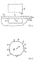
- the punching tool according to FIGS. 1 and 2 has a punch 2 and as a counterpart a bracket 10 with a Recess 11 on.
- a bracket 10 with a Recess 11 on the bracket (support body, support, Matrix) 10 is a preferably plate-shaped one to be punched Hub body 3, which in particular a uniform Can have thickness.
- the thickness of the hub body 3 is marked with d.
- the stamp 2 has on the contour (Cutting contour) of its, preferably essentially flat, Bottom 20 several, for example as shown four, cutting edges 21 to 24 and two each of these Cutting edges 21 to 24 connecting cutting edges 25.
- the cutting edges 21 to 24 take radially, i.e. in your Distance to a central axis A of the cutting punch 2 in one predetermined circumferential direction (in the polar angle direction), here clockwise, monotonous or even strictly monotonous (continuously) too. As seen in FIG 2 clockwise is the radial slope (change in distance from the Central axis A with the polar angle) of the cutting edges 21 to 24 therefore greater than or equal to or always greater than zero.
- the cutting edges 21 to 24 the shape of Spiral sections, preferably logarithmic spiral sections, exhibit. With logarithmic spiral sections is the radial slope in the circumferential direction constant.
- the slopes (derivation of the radial distance according to the polar angle) of the radially rising or falling Wall areas of the hub or shaft are particularly chosen between 0.005 and 0.02, both in embodiments with a constant gradient in the circumferential direction as well as with increasing or decreasing in the circumferential direction Pitch.
- the cutting edges 25 are essentially rectilinear and radially aligned. Exactly However, the shape of the cutting edges 25 is not important. In particular, the cutting edges 25 can also have a flatter one Have course. However, the cutting edges 25 in The circumferential direction may be less than the cutting edges 21 to 24.
- an outward Cutting projection 26 provided which, as shown, can be convex, but also concave and one has a greater radial distance from the central axis A. than the cutting edge 23 on the cutting projection 26 adjacent area.
- the Cutting edges 21 to 24 are rotationally symmetrical to one another arranged that with a rotation of the cutting punch 2 is congruent about its central axis A by 90 degrees in each case (Congruence), with the exception of the cutting projection 26, is reached. So it is mathematically one four-fold rotational symmetry of the cutting punch 2 with respect to the central axis A as an axis of symmetry.
- the radial slope of each be constant or too in the circumferential direction can decrease.
- the cutting punch 2 then generally has with respect to the central axis A one of the number of The corresponding number of cutting edges.
- the cutting tool 2 does not have to be rotationally symmetrical, however the cutting edges can also be asymmetrical the central axis A, being arranged on the others Then outer wall areas of the cutting tool 2 in particular a cylindrical shape can be selected.
- the stamp 2 according to FIG a punching direction parallel to the central axis A. led to the hub body 3 along the arrow shown and by this with a predetermined punching force (Punching pressure), which depends on the material of the hub body 3, the thickness d of the hub body 3 and the shape and material properties of the punch 2 selected is pressed.
- a predetermined punching force Pierching pressure
- the punch 2 With its underside 20 on the surface of the hub body 3 are deformation processes in the hub body 3 reduced when punching.
- the stamp 2 is after the Cut the hub body 3 a little further into the Recess 11 of the bracket 10 moves and then stopped.
- the recess 11 of the bracket 10 is preferably the Shape, in particular the cross-sectional contour, of the punch 2 adjusted so that the secondary body 3 along the edge the recess 11 is optimally supported by the holder 10 is and a clean die cut essentially achieved without (other) deformation of the hub body 3 becomes.
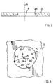
- FIGS. 1 and 2 The result of the stamping process according to FIGS. 1 and 2 is shown in Figures 3 and 4.
- the Inner wall 40 has a height that the thickness d of the hub body 3 corresponds.
- the shape of the punch 2 2 is transferred to the hub 4 according to FIG.
- the convex shape of the punch 2 is formed in a correspondingly concave shape of the hub 4.
- the central axis A of the punch 2 is parallel to this Center axis A selected punching direction now also the hub axis the hub 4.
- the hub 4 now points to it Inner wall 40 four in the circumferential direction, in plan view 4 clockwise from the top, radially rising Inner wall sections (wedge surfaces) 41 to 44 on, each with the inner wall portions 45 together are connected.
- the inner wall sections 41 to 44 correspond in their contours to the contours of the cutting edges 21 to 24 of the punch 2.
- the radial increase in the inner wall sections 41 to 44 the hub 4 is illustrated in the inner wall portion 42.
- the distance of the radially innermost Initial portion of the inner wall portion 42 of the hub axis A, hereinafter also called the radius designated R1 the radius of the radially outermost lying end portion of the inner wall portion 42 with R2.
- the radial increase in the distance of the inner wall section 42 of the hub axis A in the circumferential direction, corresponding to that between the radii R1 and R2 Polar angle ⁇ , is thus (R2-R1) / ⁇
- the increase (Slope) dR / d ⁇ (derivation of the radial distance R according to the polar angle ⁇ ) at each location of the inner wall section 42 is equal to (R2-R1) / ⁇ (constant slope) or varies (variable incline).
- the slopes dR / d ⁇ the radially rising inner wall sections 41 to 44 the hub 4 are chosen in particular between 0.005 and 0.02, both in embodiments with in the circumferential direction constant slope as well as increasing in the circumferential direction Pitch.
- the maximum difference can be between 5 mm and 60 mm R2-R1 between the radially farthest inside and outermost regions of the inner wall 40 thus turn out to be relatively small, typically accordingly between 0.2 mm and 2 mm.
- the inner wall portion 43 that is from the cutting edge 23 was cut, has an indentation 46 that the cutting projection 26 has cut free during punching.
- the indentation 46 is concave with respect to the hub body 3 shaped and protrudes further radially from the central axis A. outside as the surrounding areas of the inner wall portion 42 the hub 4.
- the distance between the farthest from the hub axis A area and the am next area of the inner wall to the hub axis A 50 in the indentation 46 is marked r for me.
- the dimension r is generally chosen to be significantly smaller than the inner radius R1 of the hub 4.
- the radial dimension r of the indentation can be 5 mm and 60 mm 46 of the hub 4 is set between 0.1 mm and 1.5 mm become.
- the dimension measured in the circumferential direction can be varied in a wide range, but should be chosen as small as possible.
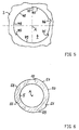
- the purpose of the indentation is based on the embodiment a shaft-hub connection according to FIGS 5 to 8 clear.
- FIG. 5 shows a hub 4 designed similarly to that in FIG. 4 with the difference that instead of four increasing radially Inner wall sections now only three inner wall sections 47, 48 and 49 are provided with respect to the central axis A with a threefold symmetry are, i.e. when rotating 120 degrees around the central axis A is the hub 4 in each case congruent, again with the exception of the indentation 46, which is in the inner wall section 47 is formed.
- FIG. 6 shows one adapted to the hub 4 according to FIG Shank (bolt) 5, which as a hollow shaft, as shown but can also be designed as a solid shaft and in particular also serve as a shaft for power transmission can.
- the inner wall sections 47 to 49 of the hub 4 correspond to corresponding, radially increasing outer wall sections 57 to 59 of the shaft 5, which over partitions 55 are connected.
- the Strength of the frictional connection i.e. the connecting forces between Shaft 5 and hub 4 is determined by the angle of rotation or determines the torque and can by not shown additional stops or a torque control exactly can be set to a predetermined value.
- the opposite of the indentation 46 of the hub 4 after the rotation area of the outer wall section to come to rest 57 of the shaft 5 is denoted by 56 in FIG lies at least immediately after turning the shaft 5 relative to the hub 4 in contrast to the other areas this outer wall portion 57 not on the inner wall 40 of the hub 4, so that there is no non-positive connection prevails.
- the shaft 5 now exists at least on its outer wall 50, but preferably in total, made of a material that at the given one, achieved after the rotation Frictional connection plastically deformed, that is, with the acting ones Forces depending on the time the connection is already gives way through structural changes.
- a plastic one Deformation is an irreversible (permanent) deformation due to the acting pressure or the acting tensile stress and starts above the elastic limit of the material (anelastic deformation).
- the material of the shaft 5 can already be a plastic one at the given adhesion Show cold flow behavior in which the material deformed even when the force is released, just flows. The flow generally sets above the so-called Yield strength of the material.
- the plastic deformation can vary according to different materials Use periods of a few minutes up to several weeks and months.
- a preferred material for the shaft 5 is a polymer material, in particular a polymer plastic, so a synthetically produced polymer or polymer mixture. Basically, here come all plastically deformable, thermoplastic and thermosetting, polymer materials in question. Without restricting generality, they are appropriate formed halogenated and non-halogenated Called hydrocarbon polymers, for example polyethylene, Polypropylene, polystyrene, polyurethane, polyvinyl chloride and fluorocarbon materials.
- the shaft 5 is preferably used as a molded part in a casting or injection molding process manufactured.
- the hub body 3 is preferably made of a given one Do not yield or only negligibly yield Material formed to securely lock the To ensure extension 56 'in the recess 46.
- a dimensionally stable material is in particular a metal such as a steel or aluminum or an aluminum alloy or a corresponding plastic, for example a fiber-reinforced plastic.
- the sheet of the hub body 3 can be stamped after the hub 4 and also before the insertion of the shaft 5 in an intermediate step be enamelled. It has surprisingly turned out to be shown that in the shaft-hub connection according to the Invention through the flat connection and uniform Power transmission also called the enamel burn Enamel accumulation on the edges of the punched hole in the hub 4 not causing the email to flake off during the connection leads, as is often the case with conventional screw connections Case is.
- the thickness d of the hub body 3 is that described so far Embodiments as sheet metal in general at most 5 mm, so that a punching process is possible without any problems is, and preferably at most 1 mm, especially around material save. It has been shown that even with these comparatively small thicknesses d or depths of the hub 4 nevertheless a secure and durable connection between the Hub 4 and the shaft 5 is possible.
- the hub 4 can also be produced by another process in addition to punching, for example by deep drawing, material removal such as milling or directly in a molded part in a casting process.
- a hub or shaft-hub connection with a structure known from one of the publications DE 42 09 153 C2 or DE 196 33 541 A1 or from WO 94/07040 A1 or WO 92 16763 A1 can be used .
- the indentation 46 of the hub 4 can also be closed all around, with the exception of the shaft 5, so that the engaging extension 56 'of the shaft 5 also provides axial securing, that is to say locking against axial movement parallel to the Center axis A, is formed.
- the shaft of the connection could also be punched.
- the hub 4 can in all embodiments also on one Inner wall section several indentations or at several Inner wall sections each one or more Have indentations to the locking effect to reinforce plastic deformation of the shaft.
- An indentation can be the hub in a not shown Modification also a continuous opening to the outside have, so that the material of the shaft on the opposite Side of the hub body can emerge and the Locking effect of the lock is reinforced.
- the hub body can also 3 are formed from a plastically deformable material. It will then correspond to the shaft with one or provided several indentations, so that the material of the Hub body under load in the recess of the shaft can flow.
- the shaft-hub connection described is in a variety of application areas. Without limitation the general area here is household appliances called, in the case of most connections of components (Functional units) with each other or with carriers only relatively to bear low forces from the shaft-hub connection are.
- household appliances basically all known household appliances come in Question, in particular cooking appliances, washing machines, tumble dryers, Dishwashers, refrigerators and / or freezers, Vacuum cleaners, coffee machines, kitchen machines and mixers.
Landscapes
- Engineering & Computer Science (AREA)
- General Engineering & Computer Science (AREA)
- Mechanical Engineering (AREA)
- Shafts, Cranks, Connecting Bars, And Related Bearings (AREA)
- Iron Core Of Rotating Electric Machines (AREA)
- Mounting Of Bearings Or Others (AREA)
- Turbine Rotor Nozzle Sealing (AREA)
Abstract
Description
Die Erfindung betrifft eine Schaft-Nabe-Verbindung und Verfahren zum Herstellen einer Nabe für eine Schaft-Nabe-Verbindung.The invention relates to a shaft-hub connection and method for producing a hub for a shaft-hub connection.
Aus DE 42 09 153 C2 ist eine Welle-Nabe-Verbindung bekannt, bei der auf der Umfangsfläche der Welle eine Mehrzahl keilförmiger Erhebungen und auf der Innenfläche der Nabe die gleiche Anzahl entsprechender keilförmiger Ausnehmungen angeordnet sind und die Steigung der Keilflächen im wesentlichen den Verlauf einer logarithmischen Spirale folgt und so flach ist, daß in Abhängigkeit von Material und Beschaffenheit der Oberflächen der Keilflächen sichere Selbsthemmung gegeben ist. Durch eine Drehbewegung der Nabe relativ zur Welle tritt nämlich zwischen den korrespondierenden Keilflächen von Welle und Nabe zunächst eine flächige Berührung, dann ein Reibschluß und bei noch weiterer Drehung schließlich eine rasch zunehmende, überall gleich hohe Flächenpressung (Kraftschluß, Preßverbindung) zwischen den Keilflächen ein. Die Drehbewegung wird fortgesetzt, bis entweder das vorgesehene, zu übertragende Moment oder die vorgesehene Winkelstellung zwischen Welle und Nabe erreicht ist. Zum Herstellen der Teilflächen von Welle und Nabe sind in der DE 42 09 153 C2 ein Verfahren zur Abtragung von Material wie Fräsen oder Hobeln sowie ein Strangpreß- oder Strangziehverfahren angegeben. Als Materialien für Welle und Nabe sind Stahl, Leichtmetall und Kunststoff angegeben. Als Anwendungen sind die Verbindung von Nocken auf einer Nockenwelle oder von Zahnrädern auf einer Getriebewelle eines Kraftfahrzeugs, die Verbindung von Streckwerkswalzenabschnitten, beispielsweise bei Spinnereimaschinen, ein Wirkmaschinen-Gelenkgetriebe und die Verbindung von Rohren in Rohrkonstruktionen wie Geländern an Treppen oder Maschinen, Spulengatter für Textilmaschinen oder Leitern beschrieben.From DE 42 09 153 C2 a shaft-hub connection is known in which a plurality of wedge-shaped elevations are arranged on the circumferential surface of the shaft and the same number of corresponding wedge-shaped recesses are arranged on the inner surface of the hub and the slope of the wedge surfaces essentially follows the course of a follows logarithmic spiral and is so flat that, depending on the material and nature of the surfaces of the wedge surfaces, there is reliable self-locking. By rotating the hub relative to the shaft, there is first a flat contact between the corresponding wedge surfaces of the shaft and hub, then a frictional engagement and, with further rotation, finally a rapidly increasing, everywhere equally high surface pressure (frictional connection, press connection) between the wedge surfaces. The rotary movement continues until either the intended torque to be transmitted or the intended angular position between shaft and hub is reached. DE 42 09 153 C2 specifies a method for removing material such as milling or planing and an extrusion or extrusion method for producing the partial surfaces of the shaft and hub. Steel, light metal and plastic are specified as materials for the shaft and hub. Applications include the connection of cams on a camshaft or of gearwheels on a transmission shaft of a motor vehicle, the connection of drafting roller sections, for example in spinning machines, a knitting machine gearbox and the connection of pipes in tubular structures such as railings on stairs or machines, creel for textile machines or Described ladders.
Aus der DE 196 33 541 A1 ist eine Weiterbildung der aus der
DE 42 09 153 C2 bekannten Welle-Nabe-Verbindung bekannt,
bei der auf der Außenumfangsfläche der Welle und/Oder Innenumfangsfläche
der Nabe in axialer Richtung der Welle
bzw. Nabe zusätzlich zu den Keilflächen zumindest eine Erhebung
und/oder eine Vertiefung zur axialen Sicherung der
Verbindung angeordnet sind. Insbesondere können diese Erhebungen
und Vertiefungen derart angeordnet sein, daß eine
Art Gewinde entsteht, so daß in einer Ausführung als Bolzen
für die Welle und einer Mutter für die Nabe ein Ersatz für
eine Schraubverbindung angegeben wird, bei der zusätzlich
zu der Axialsicherung eine axiale Vorspannkraft ähnlich einer
üblichen Gewindeschraube erzeugt wird.From DE 196 33 541 A1 a further development of the shaft-hub connection known from
Bei einer aus DE 42 09 153 C2 oder DE 196 33 541 A1 bekannten Welle-Nabe-Verbindung (Schaft-Nabe-Verbindung) treten Probleme bei der Festigkeit der Verbindung auf, wenn Schaft und/oder Nabe aus einem Kunststoff bestehen. Aufgrund der hohen Preßdrücke auf der Wandung des aus Kunststoff bestehenden Teils kann es zu plastischen Verformungen und insbesondere einem Fließen des Kunststoffes kommen. Dies sind komplexe Vorgänge, die vom konkreten Kunststoffmaterial abhängen. Vereinfacht ausgedrückt, gibt der Kunststoff durch irreversible Strukturänderungen und Verformung dem auf ihm lastenden Druck nach und fließt von den Stellen des hohen Druckes weg. Man spricht diesen Effekt auch Kaltfluß, weil er auch bei Raumtemperatur im festen Kunststoff auftritt. Die plastische Verformung des Kunststoffes, insbesondere der Kaltfluß, setzt die wirkenden Preßkräfte der Preßverbindung zwischen Schaft und Nabe herab. Dadurch ist die Selbsthemmung der Schaft-Nabe-Verbindung herabgesetzt oder sogar ausgesetzt, so daß sich die Verbindung unbeabsichtigt lösen kann.In a shaft-hub connection (shaft-hub connection) known from DE 42 09 153 C2 or DE 196 33 541 A1 , problems arise in the strength of the connection if the shaft and / or hub consist of a plastic. Due to the high pressures on the wall of the part made of plastic, plastic deformations and in particular a flow of the plastic can occur. These are complex processes that depend on the specific plastic material. Put simply, the plastic yields to the pressure on it through irreversible structural changes and deformation and flows away from the points of high pressure. This effect is also called cold flow because it occurs in the solid plastic even at room temperature. The plastic deformation of the plastic, in particular the cold flow, reduces the effective pressing forces of the press connection between the shaft and the hub. As a result, the self-locking of the shaft-hub connection is reduced or even exposed, so that the connection can be released unintentionally.
Der Erfindung liegt nun die Aufgabe zugrunde, eine Schaft-Nabe-Verbindung, bei der die genannten Nachteile des Standes der Technik beseitigt sind, sowie ein einfaches und kostengünstiges Verfahren zum Herstellen einer Nabe für eine solche Schaft-Nabe-Verbindung anzugeben.The invention is based on the object, a shaft-hub connection, at the mentioned disadvantages of the stand the technology are eliminated, as well as a simple and inexpensive Process for manufacturing a hub for a to specify such a shaft-hub connection.
Diese Aufgabe wird gemäß der Erfindung gelöst mit den Merkmalen
des Anspruchs 1 bzw. des Anspruchs 12.This object is achieved according to the invention with the features
of
Die Schaft-Nabe-Verbindung umfaßt
wobei
in which
Durch diese Maßnahmen wird erreicht, daß nach einer definierten Drehbewegung zwischen Schaft und Nabe sich der vorgegebene Kraftschluß zwischen den aufeinandergepreßten Wandungsbereichen von Nabe und Schaft einstellt mit Ausnahme jedes Bereiches, in dem eine Einbuchtung oder Öffnung in der Innenwandung der Nabe angeordnet ist. Gegenüber einer Einbuchtung oder Öffnung der Innenwandung der Nabe wäre die Außenwandung des Schaftes, falls keine Verformung des Schaftmaterials einträte, nämlich von der Nabenwandung beabstandet. Da das Material des Schaftes jedoch sich beim vorgegebenen Kraftschluß in den Bereichen mit Preßverbindung durch den ausgeübten Preßdruck plastisch zu verformen beginnt, dringt das Schaftmaterial wegen des im jeder Einbuchtung bzw. Öffnung der Nabe gegenüberliegenden Bereich des Schaftes nicht vorhandenen Druckes in die jeweilige Einbuchtung oder Öffnung der Nabe ein. Durch dieses gezielte Ausweichen des Schaftmaterials in die Einbuchtung oder Öffnung der Nabe werden aus dem Schaft Ausbuchtungen (Fortsätze, Vorsprünge) gebildet, die bei entsprechender Anpassung der Dimensionen jeder Einbuchtung bzw. Öffnung der Nabe in Formschluß und gegebenenfalls auch Kraftschluß mit der Innenwandung der Nabe treten. So kann der durch die plastische Verformung des Materials des Schaftes reduzierte Kraftschluß und die dadurch vergrößerte Gefahr eines unbeabsichtigten Lösens der Schaft-Nabe-Verbindung durch eine Arretierung des Schaftes in der Nabe mittels der in der Einbuchtung oder Öffnung der Nabe eingreifenden Ausbuchtung des Schaftes kompensiert werden. Wenn das Schaftmaterial bei dem vorgegebenen Kraftschluß bereits ein Kaltfließverhalten aufweist, also seine plastische Ausdehnung auch bei Druckentlastung weiter zunimmt, wird der Formschluß und gegebenfalls auch Kraftschluß des Schaftmaterials mit der Innenwandung der Nabe auch in der Einbuchtung bzw. Öffnung noch zusätzlich unterstützt. Das an sich für die Festigkeit der Schaft-Nabe-Verbindung nachteilige plastische Verformen und insbesondere Fließen des Materials des Schaftes bei Herstellen der Preßverbindung zwischen Schaft und Nabe wird somit gemäß der Erfindung in einen Vorteil umgemünzt, indem das fließende Material zum Bilden einer Anschlagssicherung (Arretierung) für die Schaft-Nabe-Verbindung ausgenutzt wird. Die Sicherung der Schaft-Nabe-Verbindung durch die beschriebene Arretierung kann nicht nur gegen eine Drehbewegung wirksam sein (Drehsicherung), sondern bei entsprechender Auslegung der Einbuchtung bzw. Öffnung in der Nabe auch gegen eine Axialbewegung (Axialsicherung).These measures ensure that according to a defined The rotational movement between the shaft and hub is the specified one Non-positive connection between the pressed wall areas of hub and shaft sets with exception any area in which an indentation or opening in the inner wall of the hub is arranged. Opposite one The indentation or opening of the inner wall of the hub would be the Outer wall of the shaft if there is no deformation of the Shaft material would occur, namely spaced from the hub wall. However, since the material of the shaft is different predetermined adhesion in the areas with press connection plastically deformed by the applied pressure begins, the shaft material penetrates because of the im every indentation or opening of the hub opposite area of the stem pressure not present in the respective Indentation or opening of the hub. Through this targeted Dodge the shaft material into the indentation or Opening of the hub bulges (extensions, Projections) formed with appropriate adjustment the dimensions of each indentation or opening of the hub in positive engagement and, if necessary, also with positive engagement the inner wall of the hub. So he can through the plastic deformation of the material of the shaft reduced Traction and the resulting increased risk of accidental Loosen the shaft-hub connection with a Locking the shaft in the hub by means of the Indentation or opening of the boss engaging bulge of the shaft can be compensated. If the shaft material a cold flow behavior at the given adhesion has, so its plastic expansion also at Pressure relief increases further, the positive locking and, if necessary also frictional connection of the shaft material with the inner wall the hub also in the indentation or opening additionally supported. That in itself for strength the shaft-hub connection disadvantageous plastic deformation and in particular flow of the material of the shaft Establish the press connection between the shaft and hub thus converted into an advantage according to the invention by the flowing material to form a stop safety device (Locking) used for the shaft-hub connection becomes. The shaft-hub connection is secured by the described locking can not only against a rotational movement be effective (rotation lock), but with the appropriate one Design of the indentation or opening in the hub also against axial movement (axial locking).
Vorteilhafte Weiterbildungen und Ausgestaltungen gemäß der
Erfindung ergeben sich aus den vom Anspruch 1 abhängigen
Ansprüchen.Advantageous further developments and refinements according to the
Invention result from those dependent on
Das plastisch verformbare Material für den Schaft bzw. die Nabe ist vorzugsweise ein Polymer-Werkstoff.The plastically deformable material for the shaft or the The hub is preferably a polymer material.
Es kann nun vorzugsweise das zum jeweiligen Verbindungsteil (Schaft oder Nabe), das mit plastisch verformbarem Material gebildet ist, korrespondierende Verbindungsteil (Nabe bzw. Schaft) der Schaft-Nabe-Verbindung zumindest an der Verbindungfläche aus einem beim vorgegebenen Kraftschluß nicht plastisch verformbaren Material bestehen, insbesondere aus einem Metall, beispielsweise Stahl oder Aluminium, oder auch einem faserverstärkten Kunststoff.It can now preferably do that for the respective connecting part (Shaft or hub), which with plastically deformable material is formed, corresponding connecting part (hub or Shaft) of the shaft-hub connection at least at the connection surface not from a given adhesion plastically deformable material consist, in particular a metal, for example steel or aluminum, or also a fiber-reinforced plastic.
Die Einbuchtung oder Öffnung kann nun in einer ersten Weiterbildung parallel zur Nabenachse bzw. Schaftachse offen sein, insbesondere in Gestalt einer Rille. Die Arretierung durch den ausgeformten Fortsatz und die korrespondierende Einbuchtung bzw. Öffnung wirkt dann nur in Drehrichtung.The indentation or opening can now be used in a first development open parallel to the hub axis or shaft axis be, especially in the form of a groove. The lock through the shaped extension and the corresponding The indentation or opening only acts in the direction of rotation.
Um die Arretierung sowohl gegen Drehung als auch axial, i.e. parallel zur Mittelachse von Nabe oder Schaft, zu erreichen, ist die Einbuchtung oder Öffnung in einer vorteilhaften zweiten Weiterbildung an den nicht an der Verbindungfläche liegenden Seiten geschlossen, so daß in allen Richtungen eine Sicherung gewährleistet ist.To lock both against rotation and axially, i.e. parallel to the central axis of the hub or shaft, the indentation or opening is advantageous second training at the not at the interface lying sides closed, so that in all Directions a backup is guaranteed.
Es können auch an der Innenwandung der Nabe bzw. der Außenwandung des Schaftes mehrere Einbuchtungen oder Öffnungen vorgesehen sein.It can also on the inner wall of the hub or the outer wall of the shaft several indentations or openings be provided.
Die Steigung der aufeinanderzupressenden Wandungsteilbereiche von Nabe und Schaft in Umfangsrichtung ist vorzugsweise im wesentlichen konstant. Man erreicht so eine homogene Kraftverteilung über die gesamte Verbindungsfläche.The slope of the wall sections to be pressed together circumferential hub and shaft is preferred essentially constant. You achieve a homogeneous one Force distribution over the entire connection area.
Die Nabe wird in einer vorteilhaften Ausführungsform bezuglich der Nabenachse mit einer Rotationssymmetrie einer vorgegebenen Zähligkeit erzeugt, insbesondere indem die Schneidkanten des Stanzstempels eine entsprechende Symmetrie aufweisen. Der demnach entsprechend symmetrische Schaft wird in dieser Ausführungsform bei der Drehung automatisch in der Nabe zentriert (selbstzentrierte Verbindung).In an advantageous embodiment, the hub is relevant the hub axis with a rotational symmetry of a predetermined Generated number, especially by the Cutting edges of the punch a corresponding symmetry exhibit. The correspondingly symmetrical one In this embodiment, the shaft becomes automatic when rotating centered in the hub (self-centered connection).
Die Maßnahmen gemäß der Erfindung sind demnach besonders vorteilhaft bei einer Schaft-Nabe-Verbindung mit einer flachen Nabe, insbesondere einer durch Stanzen eines Nabenkörpers erzeugten Nabe. Die Innenwandung der Nabe weist dann insbesondere eine parallel zur Nabenachse gemessene Höhe von höchstens etwa 5 mm, vorzugsweise höchstens 1 mm, auf. Insbesondere bei solchen Schaft-Nabe-Verbindungen kann das Fließen des Schaftmaterials die Verbindung lockern.The measures according to the invention are therefore special advantageous for a shaft-hub connection with a flat one Hub, especially one by punching a hub body generated hub. The inner wall of the hub then faces in particular a height measured parallel to the hub axis of at most about 5 mm, preferably at most 1 mm. In particular with such shaft-hub connections, this can Flowing the shaft material loosen the connection.
Ein bevorzugtes Verfahren zum Herstellen einer Nabe für die Schaft-Nabe-Verbindung ist gemäß Anspruch 12 ein Stanzprozeß.A preferred method of making a hub for the Shaft-hub connection is a stamping process according to claim 12.
Zur weiteren Erläuterung der Erfindung wird auf die Zeichnungen Bezug genommen, in denen Ausführungsbeispiele gemäß der Erfindung jeweils schematisch dargestellt sind. Es zeigen:
- FIG 1
- einen Nabenkörper und ein Stanzwerkzeug in einem seitlichen Schnitt,
- FIG 2
- das Stanzwerkzeug gemäß FIG 1 in einer Ansicht von unten,
- FIG 3
- eine gestanzte Nabe in einem Nabenkörper in einem seitlichen Schnitt,
- FIG 4
- die gestanzte Nabe gemäß FIG 3 in einer Draufsicht,
- FIG 5
- eine Nabe in einer Draufsicht,
- FIG 6
- einen zur Nabe gemäß FIG 5 korrespondierenden Schaft
- FIG 7
- eine Schaft-Nabe-Verbindung mit einer Nabe gemäß FIG 5 und einem Schaft gemäß FIG 6,
- FIG 8
- eine Schaft-Nabe-Verbindung mit einer Nabe gemäß FIG 5 und einem schaft gemäß FIG 6, bei der der Schaft plastisch verformt ist.
- FIG. 1
- a hub body and a punching tool in a lateral section,
- FIG 2
- 1 in a view from below,
- FIG 3
- a stamped hub in a hub body in a side cut,
- FIG 4
- the punched hub according to FIG 3 in a plan view,
- FIG 5
- a hub in a top view,
- FIG 6
- a shaft corresponding to the hub according to FIG. 5
- FIG 7
- 5 shows a shaft-hub connection with a hub according to FIG. 5 and a shaft according to FIG. 6,
- FIG 8
- a shaft-hub connection with a hub according to FIG 5 and a shaft according to FIG 6, in which the shaft is plastically deformed.
Das Stanzwerkzeug gemäß den FIG 1 und 2 weist einen Stanzstempel
2 und als Gegenstück eine Halterung 10 mit einer
Ausnehmung 11 auf. Auf der Halterung (Tragekörper, Auflage,
Matrix) 10 liegt ein zu stanzender, vorzugsweise plattenförmiger
Nabenkörper 3 auf, der insbesondere eine gleichmäßige
Dicke aufweisen kann. Die Dicke des Nabenkörpers 3 ist
mit d bezeichnet. Der Stanzstempel 2 weist an der Kontur
(Schneidkontur) seiner, vorzugsweise im wesentlichen flachen,
Unterseite 20 mehrere, beispielsweise wie dargestellt
vier, Schneidkanten 21 bis 24 und jeweils zwei dieser
Schneidkanten 21 bis 24 verbindende Schneidkanten 25 auf.The punching tool according to FIGS. 1 and 2 has a
Die Schneidkanten 21 bis 24 nehmen radial, d.h. in ihrem
Abstand zu einer Mittelachse A des Schneidstempels 2 in einer
vorgegebenen Umfangsrichtung (in Polarwinkelrichtung),
hier im Uhrzeigersinn, monoton oder sogar streng monoton
(kontinuierlich) zu. Gemäß FIG 2 im Uhrzeigersinn gesehen
ist die radiale Steigung (Änderung des Abstands von der
Mittelachse A mit dem Polarwinkel) der Schneidkanten 21 bis
24 also größer oder gleich bzw. immer größer Null. Insbesondere
können die Schneidkanten 21 bis 24 die Gestalt von
Spiralenabschnitten, vorzugsweise von logarithmischen Spiralenabschnitten,
aufweisen. Bei logarithmischen Spiralenabschnitten
ist die radiale Steigung in der Umfangsrichtung
konstant. Die Steigungen (Ableitung des radialen Abstandes
nach dem Polarwinkel) der radial ansteigenden oder abfallenden
Wandbereiche der Nabe oder des Schaftes werden insbesondere
zwischen 0,005 und 0,02 gewählt, sowohl bei Ausführungsformen
mit in Umfangsrichtung konstanter Steigung
als auch mit in Umfangsrichtung zunehmender oder abnehmender
Steigung.The cutting edges 21 to 24 take radially, i.e. in your
Distance to a central axis A of the cutting
Zwischen den einzelnen Schneidkanten 21 bis 24 liegt jeweils
eine Schneidkante 25, die die beiden benachbarten
Schneidkanten 21 und 22 bzw. 22 und 23 bzw. 23 und 24 bzw.
24 und 21 miteinander verbindet. Im dargestellten Ausführungsbeispiel
gemäß FIG 2 sind die Schneidkanten 25 im wesentlichen
geradlinig und radial ausgerichtet. Auf die genaue
Form der Schneidkanten 25 kommt es jedoch nicht an.
Insbesondere können die Schneidkanten 25 auch einen flacheren
Verlauf haben. Jedoch sollten die Schneidkanten 25 in
Umfangsrichtung geringer ausgedehnt sein als die Schneidkanten
21 bis 24.Between the
An wenigstens einer der Schneidkanten, im Beispiel gemäß
FIG 2 an der Schneidkante 23, ist nun ein nach außen gerichteter
Schneidvorsprung 26 vorgesehen, der, wie dargestellt,
konvex, aber auch konkav geformt sein kann und einen
größeren radialen Abstand von der Mittelachse A aufweist
als die Schneidkante 23 im an den Schneidvorsprung 26
angrenzenden Bereich.On at least one of the cutting edges, according to the example in the example
2 on the
Im dargestellten Ausführungsbeispiel gemäß FIG 2 sind die
Schneidkanten 21 bis 24 derart rotationssymmetrisch zueinander
angeordnet, daß bei einer Drehung des Schneidstempels
2 um seine Mittelachse A um jeweils 90 Grad eine Deckungsgleichheit
(Kongruenz), mit Ausnahme des Schneidvorsprungs
26, erreicht wird. Es liegt also -mathematisch ausgedrückteine
vierzählige Rotationssymmetrie des Schneidstempels 2
bezüglich der Mittelachse A als Symmetrieachse vor. In the illustrated embodiment according to FIG 2, the
Cutting edges 21 to 24 are rotationally symmetrical to one another
arranged that with a rotation of the cutting
In Abweichung von FIG 2 können auch weniger oder mehr
Schneidkanten vorgesehen sein, deren radiale Steigung jeweils
konstant sein oder auch in Umfangsrichtung zu- oder
abnehmen kann. Der Schneidstempel 2 weist dann im allgemeinen
bezüglich der Mittelachse A eine der Anzahl der
Schneidkanten entsprechende Zähligkeit auf. Das Schneidwerkzeug
2 muß aber nicht rotationssymmetrisch sein, sondern
es können die Schneidkanten auch asymmetrisch bezüglich
der Mittelachse A angeordnet sein, wobei an den übrigen
Außenwandungsbereichen des Schneidwerkzeuges 2 dann
insbesondere eine zylindrische Form gewählt werden kann.In deviation from FIG 2 less or more can also
Cutting edges are provided, the radial slope of each
be constant or too in the circumferential direction
can decrease. The cutting
Beim Stanzprozeß wird nun der Stanzstempel 2 gemäß FIG 1 in
einer parallel zur Mittelachse A liegenden Stanzrichtung
entlang des dargestellten Pfeiles zu dem Nabenkörper 3 geführt
und durch diesen mit einer vorgegebenen Stanzkraft
(Stanzdruck), die in Abhängigkeit von dem Material des Nabenkörpers
3, der Dicke d des Nabenkörpers 3 und der Form
und Materialbeschaffenheit des Stanzwerkzeugs 2 gewählt
ist, gedrückt. Durch das flächige Aufsetzen des Stanzstempels
2 mit seiner Unterseite 20 auf die Oberfläche des Nabenkörpers
3 werden Verformungsprozesse im Nabenkörper 3
beim Stanzen reduziert. Der Stanzstempel 2 wird nach dem
Durchschneiden des Nabenkörpers 3 noch ein Stück in die
Ausnehmung 11 der Halterung 10 bewegt und dann angehalten.
Die Ausnehmung 11 der Halterung 10 ist vorzugsweise der
Form, insbesondere der Querschnittskontur, des Stanzstempels
2 angepaßt, so daß der Nebenkörper 3 entlang des Randes
der Ausnehmung 11 von der Halterung 10 optimal abgestützt
ist und ein sauberer Stanzschnitt im wesentlichen
ohne eine (sonstige) Verformung des Nabenkörpers 3 erreicht
wird. In the stamping process, the
Das Ergebnis des Stanzprozesses gemäß den FIG 1 und 2 ist
in den FIG 3 und 4 dargestellt. In dem Nabenkörper 3 ist
als Nabe 4 ein Loch ausgestanzt (ausgeschnitten), dessen
Innenwandung 40 eine Höhe aufweist, die der Dicke d des Nabenkörpers
3 entspricht. Die Gestalt des Stanzstempels 2
gemäß FIG 2 ist gemäß FIG 4 auf die Nabe 4 übertragen. Die
konvexe Gestalt des Stanzstempels 2 bildet sich dabei in
eine entsprechend konkave Gestalt der Nabe 4 ab. Die Mittelachse
A des Stanzstempels 2 ist durch die parallel zu dieser
Mittelachse A gewählte Stanzrichtung nun auch die Nabenachse
der Nabe 4. Im einzelnen weist die Nabe 4 nun an ihrer
Innenwandung 40 vier in Umfangsrichtung, in der Draufsicht
von oben gemäß FIG 4 im Uhrzeigersinn, radial ansteigende
Innenwandungsteilbereiche (Keilflächen) 41 bis 44
auf, die jeweils über Innenwandungsteilbereiche 45 miteinander
verbunden sind. Die Innenwandungsteilbereiche 41 bis
44 entsprechen in ihrer Kontur den Konturen der Schneidkanten
21 bis 24 des Stanzstempels 2.The result of the stamping process according to FIGS. 1 and 2 is
shown in Figures 3 and 4. In the
Die radiale Zunahme der Innenwandungsteilbereiche 41 bis 44
der Nabe 4 ist bei dem Innenwandungsteilbereich 42 veranschaulicht.
Der Abstand des radial am weitesten innen liegenden
Anfangsabschnittes des Innenwandungsteilbereiches 42
von der Nabenachse A, im folgenden auch Radius genannt, ist
mit R1 bezeichnet, der Radius des radial am weitesten außen
liegenden Endabschnittes des Innenwandungsteilbereiches 42
mit R2. Die radiale Zunahme des Abstandes des Innenwandungsteilbereiches
42 von der Nabenachse A in Umfangsrichtung,
entsprechend dem zwischen den Radien R1 und R2 liegenden
Polarwinkel ϕ, ist somit (R2-R1)/ϕ, wobei die Zunahme
(Steigung) dR/dϕ (Ableitung des radialen Abstandes R
nach dem Polarwinkel ϕ) an jedem Ort der Innenwandungsteilbereiches
42 gleich (R2-R1)/ϕ ist (konstante Steigung) oder
variiert (veränderliche Steigung). Die Steigungen dR/dϕ der
radial ansteigenden Innenwandungsteilbereichen 41 bis 44
der Nabe 4 werden insbesondere zwischen 0,005 und 0,02 gewählt,
sowohl bei Ausführungsformen mit in Umfangsrichtung
konstanter Steigung als auch mit in Umfangsrichtung zunehmender
Steigung. Bei einem Radius R1 der Nabe 4 von beispielsweise
zwischen 5 mm und 60 mm kann der maximale Unterschied
R2-R1 zwischen den radial am weitesten innen und
am weitesten außen liegenden Bereichen der Innenwandung 40
somit relativ gering ausfallen, typischerweise entsprechend
zwischen 0,2 mm und 2 mm.The radial increase in the inner wall sections 41 to 44
the
Der Innenwandungsteilbereich 43, der von der Schneidkante
23 geschnitten wurde, weist eine Einbuchtung 46 auf, die
der Schneidvorsprung 26 beim Stanzen freigeschnitten hat.
Die Einbuchtung 46 ist bezogen auf den Nabenkörper 3 konkav
geformt und ragt radial von der Mittelachse A weiter nach
außen als die umliegenden Bereiche des Innenwandungsteilbereiches
42 der Nabe 4. Der Abstand zwischen dem am weitesten
von der Nabenachse A entfernten Bereich und dem am
nächsten zur Nabenachse A liegenden Bereich der Innenwandung
50 in der Einbuchtung 46 ist mir r bezeichnet. Die Abmessung
r ist im allgemeinen deutlich kleiner gewählt als
der innere Radius R1 der Nabe 4. Bei den zuvor genannten
Werten für den Radius R1 der Nabe 4 von beispielsweise zwischen
5 mm und 60 mm kann die radiale Abmessung r der Einbuchtung
46 der Nabe 4 zwischen 0,1 mm und 1,5 mm eingestellt
werden. Die in Umfangsrichtung gemessene Abmessung
kann in einem weiten Bereich variiert werden, sollte aber
möglichst klein gewählt werden.The
Der Zweck der Einbuchtung wird anhand des Ausführungsbeispieles einer Schaft-Nabe-Verbindung gemäß den FIG 5 bis 8 klar. The purpose of the indentation is based on the embodiment a shaft-hub connection according to FIGS 5 to 8 clear.
FIG 5 zeigt eine ähnlich wie in FIG 4 ausgebildete Nabe 4
mit dem Unterschied, daß anstelle von vier radial ansteigenden
Innenwandungsteilbereichen nun nur drei Innenwandungsteilbereiche
47, 48 und 49 vorgesehen sind, die bezüglich
der Mittelachse A mit einer dreizähligen Symmetrie angeordnet
sind, d.h. bei Drehung um 120 Grad um die Mittelachse
A ist die Nabe 4 jeweils deckungsgleich (kongruent),
wieder mit Ausnahme der Einbuchtung 46, die in dem Innenwandungsteilbereich
47 gebildet ist.FIG. 5 shows a
FIG 6 zeigt einen an die Nabe 4 gemäß FIG 5 angepaßten
Schaft (Bolzen) 5, der als Hohlschaft, wie dargestellt,
aber auch als massiver Schaft ausgebildet sein kann und
insbesondere auch als Welle zur Kraftübertragung dienen
kann. Den Innenwandungsteilbereichen 47 bis 49 der Nabe 4
entsprechen korrespondierende, radial zunehmende Außenwandungsteilbereiche
57 bis 59 des Schaftes 5, die über Außenwandungsteilbereiche
55 miteinander verbunden sind.6 shows one adapted to the
Die FIG 7 und 8 stellen nun die komplette Schaft-Nabe-Verbindung
mit einer Nabe 4 gemäß FIG 5 und einem Schaft 5
gemäß FIG 6 dar. Zur Verbindung wird der Schaft 5 axial,
d.h. parallel zur Mittelachse A, in die Nabe 4 derart eingefügt,
daß die Außenwandungsteilbereiche 55 des Schaftes 5
und die Innenwandungsteilbereiche 45 der Nabe 4 nahe beieinander
liegen oder einander sogar berühren. In dieser
Stellung sind Schaft 5 und Nabe 4 mit Spiel gegeneinander
beweglich, da zwischen den Außenwandungsteilbereichen 57
bis 59 des Schaftes 5 und den unmittelbar gegenüberliegenden
Innenwandungsbereichen 47 bis 49 der Nabe 4 jeweils
Spalte gebildet sind.7 and 8 now represent the complete shaft-hub connection
with a
Dieses zunächst vorhandene Spiel zwischen Schaft 5 und Nabe
4 wird nun durch Drehung zwischen Schaft 5 und Nabe 4 um
die gemeinsame Mittelachse A als Drehachse in der vorgegebenen,
durch Pfeile gekennzeichneten Drehrichtung, hier im
Uhrzeigersinn, aufgehoben. Bei diesem Verdrehen des Schaftes
5 relativ zur Nabe 4 wird nun zunächst jeder der Außenwandungsteilbereiche
57 bis 59 des Schaftes 5 mit dem korrespondierenden
Innenwandungsteilbereich 47 bis 49 der Nabe
4 in Flächenkontakt gebracht. Bei nur geringer Drehung um
einen kleinen Drehwinkel wird lediglich ein Reibschluß zwischen
den Innenwandungsteilbereichen 47 bis 49 und den Außenwandungsteilbereichen
57 bis 59 erzeugt, bei weiterer
Drehung, d.h. bei größerem Drehwinkel oder einem größeren
Drehmoment, tritt dagegen ein Kraftschluß oder eine Flächenpressung
ein (Preßverbindung). Durch die nun in Richtung
der Flächennormalen wirkenden Verbindungskräfte werden
die Außenwandungsteilbereiche 57 bis 59 des Schaftes 5 an
die entsprechenden Innenwandungsteilbereiche 47 bis 49 der
Nabe 4 gepreßt, so daß eine kraftschlüssige, selbsthemmende
Verbindung zwischen Schaft 5 und Nabe 4 erreicht wird. Die
Stärke des Kraftschlusses, also die Verbindungskräfte, zwischen
Schaft 5 und Nabe 4 wird durch den Drehwinkel oder
das Drehmoment bestimmt und kann durch nicht dargestellte
zusätzliche Anschläge oder eine Drehmomentregelung genau
auf einen vorgegebenen Wert eingestellt werden.This existing game between shaft 5 and
Der gegenüber der Einbuchtung 46 der Nabe 4 nach der Drehung
zu liegen kommende Bereich des Außenwandungsteilbereiches
57 des Schaftes 5 ist in FIG 7 mit 56 bezeichnet und
liegt zumindest unmittelbar nach dem Verdrehen des Schaftes
5 relativ zur Nabe 4 im Gegensatz zu den übrigen Bereichen
dieses Außenwandungsteilbereiches 57 nicht an der Innenwandung
40 der Nabe 4 an, so daß dort singulär kein Kraftschluß
herrscht. The opposite of the
Der Schaft 5 besteht nun zumindest an seiner Außenwandung
50, vorzugsweise jedoch insgesamt, aus einem Material, das
sich bei dem vorgegebenen, nach der Drehung erzielten
Kraftschluß plastisch verformt, also bei den wirkenden
Kräften abhängig von der Zeit, die die Verbindung bereits
besteht, durch Strukturänderungen nachgibt. Eine plastische
Verformung ist eine irreversible (bleibende) Verformung
aufgrund des wirkenden Druckes oder der wirkenden Zugspannung
und beginnt oberhalb der Elastizitätsgrenze des Materials
(anelastische Verformung). Das Material des Schaftes
5 kann bei dem vorgegebenen Kraftschluß auch schon ein plastisches
Kaltfließverhalten zeigen, bei dem sich das Material
selbst bei Kraftentlastung weiter verformt, eben
fließt. Das Fließen setzt gemeinhin oberhalb der sogenannten
Streckgrenze des Materials ein. Die plastische Verformung
kann bei unterschiedlichen Materialien nach unterschiedlichen
Zeiträumen einsetzen, die von wenigen Minuten
bis mehrere Wochen und Monate dauern können.The shaft 5 now exists at least on its
Ein bevorzugtes Material für den Schaft 5 ist ein Polymer-Werkstoff, insbesondere ein Polymer-Kunststoff, also ein synthetisch hergestelltes Polymer oder Polymergemisch. Grundsätzlich kommen hier alle plastisch verformbaren, thermoplastischen und duroplastischen, Polymermaterialien in Frage. Ohne Beschränkung der Allgemeinheit seien entsprechend gebildete halogenierte und nicht halogenierte Kohlenwasserstoffpolymere genannt, beispielsweise Polyethylen-, Polypropylen-, Polystyrol-, Polyurethan-, Polyvinylchlorid- und Fluorcarbon-Werkstoffe. Der Schaft 5 wird vorzugsweise als Formteil in einem Gieß- oder Spritzgießverfahren hergestellt.A preferred material for the shaft 5 is a polymer material, in particular a polymer plastic, so a synthetically produced polymer or polymer mixture. Basically, here come all plastically deformable, thermoplastic and thermosetting, polymer materials in question. Without restricting generality, they are appropriate formed halogenated and non-halogenated Called hydrocarbon polymers, for example polyethylene, Polypropylene, polystyrene, polyurethane, polyvinyl chloride and fluorocarbon materials. The shaft 5 is preferably used as a molded part in a casting or injection molding process manufactured.
Wenn nun die plastische Verformung im Material des Schaftes
5 nach einer materialabhängigen Zeitdauer einsetzt, so
weicht das Material an dem Außenwandungsteilbereich 57 wegen
des dort praktisch nicht vorhandenen Druckes in die
Einbuchtung 46 im Nabenkörper 3 aus. Es bildet sich somit
gemäß FIG 8 ein Fortsatz (Vorsprung, Nase, Ausbuchtung,
Ausformung) 56' aus der Außenwandung 50 des Schaftes 5 aus,
wo vorher gemäß FIG 7 der Bereich 56 war. Der Fortsatz 56'
greift in die Einbuchtung 46 formschlüssig ein und bildet
dadurch eine automatisch entstandene Arretierung, die ein
Lösen der Schaft-Nabe-Verbindung durch Drehung verhindert.If now the plastic deformation in the material of the shaft
5 starts after a material-dependent period of time, see above
the material softens on the
Der Nabenkörper 3 wird vorzugsweise aus einem beim vorgegebenen
Kraftschluß nicht oder nur vernachlässigbar nachgiebigen
Material gebildet, um eine sichere Arretierung des
Fortsatzes 56' in der Einbuchtung 46 zu gewährleisten. Ein
derart formstabiles Material ist insbesondere ein Metall
wie beispielsweise ein Stahl oder Aluminium oder eine Aluminiumlegierung
oder auch ein entsprechender Kunststoff,
beispielsweise ein faserverstärkter Kunststoff.The
Das Blech des Nabenkörpers 3 kann nach dem Stanzen der Nabe
4 und vor dem Einführen des Schafts 5 auch in einem Zwischenschritt
emailliert werden. Es hat sich überraschenderweise
gezeigt, daß bei der Schaft-Nabe-Verbindung gemäß der
Erfindung durch die flächige Verbindung und gleichmäßige
Kraftübertragung auch die als Emailabbrand bezeichnete
Emailanhäufung an den Kanten des gestanzten Loches der Nabe
4 nicht zu einem Abplatzen des Emails bei der Verbindung
führt, wie dies bei üblichen Schraubverbindungen oft der
Fall ist.The sheet of the
Die Dicke d des Nabenkörpers 3 beträgt in den bislang beschriebenen
Ausführungsformen als Blech im allgemeinen
höchstens 5 mm, so daß ein Stanzprozeß problemlos möglich
ist, und vorzugsweise höchstens 1 mm, insbesondere um Material
einzusparen. Es hat sich gezeigt, daß selbst bei diesen
vergleichsweise geringen Dicken d bzw. Tiefen der Nabe
4 dennoch eine sichere und haltbare Verbindung zwischen der
Nabe 4 und dem Schaft 5 möglich ist.The thickness d of the
Die Nabe 4 kann aber außer durch Stanzen auch durch einen
anderen Prozeß hergestellt werden, beispielsweise durch
Tiefziehen, Materialabtragung wie Fräsen oder direkt in einem
Formteil in einem Gießverfahren. Außerdem kann auch eine
Nabe bzw. Schaft-Nabe-Verbindung mit einem aus einer der
eingangs genannten Druckschriften DE 42 09 153 C2 oder DE
196 33 541 A1 oder aus der WO 94/07040 A1 oder der WO 92
16763 A1 bekannten Aufbau verwendet werden. Bei einer nicht
gestanzten Nabe kann die Einbuchtung 46 der Nabe 4 auch
ringsum mit Ausnahme zum Schaft 5 hin geschlossen ausgebildet
sein, so daß durch den eingreifenden Fortsatz 56' des
Schaftes 5 auch eine axiale Sicherung, also eine Arretierung
gegen eine axiale Bewegung parallel-zur Mittelachse A,
gebildet ist. Im übrigen könnte auch der Schaft der Verbindung
gestanzt werden.The
Die Nabe 4 kann in allen Ausführungsformen auch an einem
Innenwandungsteilbereich mehrere Einbuchtungen oder an mehreren
Innenwandungsteilbereichen jeweils eine oder mehrere
Einbuchtungen aufweisen, um die Arretierungswirkung bei
plastischer Verformung des Schaftes zu verstärken. Anstelle
einer Einbuchtung kann die Nabe in einer nicht dargestellten
Abwandlung auch eine nach außen durchgehende Öffnung
aufweisen, so daß das Material des Schaftes an der gegenüberliegenden
Seite des Nabenkörpers austreten kann und die
Sperrwirkung der Arretierung noch verstärkt wird.The
In einer anderen Ausführungsform kann auch der Nabenkörper 3 aus einem plastisch verformbaren Material gebildet werden. Es wird dann entsprechend der Schaft mit einer oder mehreren Einbuchtungen versehen, so daß das Material des Nabenkörpers bei Belastung in die Einbuchtung des Schaftes fließen kann.In another embodiment, the hub body can also 3 are formed from a plastically deformable material. It will then correspond to the shaft with one or provided several indentations, so that the material of the Hub body under load in the recess of the shaft can flow.
Die beschriebene Schaft-Nabe-Verbindung ist in einer Vielzahl von Anwendungsgebieten einsetzbar. Ohne Beschränkung der Allgemeinheit sei hier der Bereich der Haushaltsgeräte genannt, in dem bei den meisten Verbindungen von Bauteilen (Funktionseinheiten) miteinander oder mit Trägern nur relativ geringe Kräfte von der Schaft-Nabe-Verbindung zu tragen sind. Zu denken ist hier beispielsweise an die Befestigung von statischen wie drehenden Teilen an entsprechenden Trägern, insbesondere Elektromotoren, Strömungsmaschinen (Pumpen, Gebläsen) oder Kompressoren an einem Gehäuse, Drehknebeln vor einer Bedienblende an entsprechenden Steuerund/oder Regelmodulen hinter der Bedienblende, Filtern, Scharnieren an Türen und Gehäusen, Sprüharmen, Behältern, Befestigung von Rohren und Schläuchen etc. Als Haushaltsgeräte kommen grundsätzlich alle bekannten Haushaltsgeräte in Frage, insbesondere Gargeräte, Waschmaschinen, Wäschetrocknern, Geschirrspülmaschinen, Kühl-und/oder Gefriergeräte, Staubsauger, Kaffeemaschinen, Küchenmaschinen und Mixer. The shaft-hub connection described is in a variety of application areas. Without limitation the general area here is household appliances called, in the case of most connections of components (Functional units) with each other or with carriers only relatively to bear low forces from the shaft-hub connection are. One example is the attachment of static and rotating parts on appropriate supports, especially electric motors, flow machines (pumps, Blowers) or compressors on a housing, rotary knobs in front of a control panel on the corresponding control and / or Control modules behind the control panel, filters, Hinges on doors and housings, spray arms, containers, Fastening pipes and hoses etc. As household appliances basically all known household appliances come in Question, in particular cooking appliances, washing machines, tumble dryers, Dishwashers, refrigerators and / or freezers, Vacuum cleaners, coffee machines, kitchen machines and mixers.
- 22nd
- StanzstempelPunch stamp
- 33rd
- NabenkörperHub body
- 44th
- Nabehub
- 55
- Schaftshaft
- 1010th
- Halterungbracket
- 1111
- AusnehmungRecess
- 2020th
- Unterseitebottom
- 4040
- InnenwandungInner wall
- 41 bis 4541 to 45
- InnenwandungsteilbereicheInner wall sections
- 4646
- Einbuchtungindentation
- 47 bis 4847 to 48
- InnenwandungsteilbereicheInner wall sections
- 5050
- AußenwandungOuter wall
- 51 bis 5551 to 55
- AußenwandungsteilbereicheOuter wall sections
- 5656
- BereichArea
- 56'56 '
- FortsatzContinuation
- 57 bis 5857 to 58
- AußenwandungsteilbereicheOuter wall sections
- dd
- Dickethickness
- R1,R2R1, R2
- Radiusradius
- rr
- radiale Abmessungradial dimension
- AA
- Achseaxis
- ϕϕ
- PolarwinkelPolar angle
Claims (12)
wobei
in which
Applications Claiming Priority (2)
| Application Number | Priority Date | Filing Date | Title |
|---|---|---|---|
| DE19932660 | 1999-07-15 | ||
| DE19932660A DE19932660C2 (en) | 1999-07-15 | 1999-07-15 | Shaft-hub connection with locking in case of plastic deformation |
Publications (2)
| Publication Number | Publication Date |
|---|---|
| EP1069325A2 true EP1069325A2 (en) | 2001-01-17 |
| EP1069325A3 EP1069325A3 (en) | 2002-05-29 |
Family
ID=7914582
Family Applications (1)
| Application Number | Title | Priority Date | Filing Date |
|---|---|---|---|
| EP00111726A Withdrawn EP1069325A3 (en) | 1999-07-15 | 2000-06-02 | Shaft-to-hub fastening with plastic deformation |
Country Status (2)
| Country | Link |
|---|---|
| EP (1) | EP1069325A3 (en) |
| DE (1) | DE19932660C2 (en) |
Cited By (1)
| Publication number | Priority date | Publication date | Assignee | Title |
|---|---|---|---|---|
| WO2008012074A1 (en) | 2006-07-25 | 2008-01-31 | Winker Massivumformung Gmbh & Co. Kg | Safety nut |
Families Citing this family (6)
| Publication number | Priority date | Publication date | Assignee | Title |
|---|---|---|---|---|
| DE10342278B4 (en) * | 2003-03-28 | 2005-12-08 | J. Kühl - 3K - Engineering | Shaft / hub connection with tendon |
| DE102008014891B4 (en) * | 2008-03-19 | 2010-02-18 | Isringhausen Gmbh & Co. Kg | Armrest attachment and method for joining an armrest attachment |
| DE102009038080A1 (en) | 2009-08-19 | 2011-03-03 | Audi Ag | Connecting arrangement for high pressure fuel pump of internal combustion engine, has recess circulating in circumferential direction of connecting element, where contour of another connecting element is accommodated in sections by recess |
| US8979417B2 (en) | 2011-07-14 | 2015-03-17 | Volkswagen Aktiengesellschaft | Attachment system |
| US9150145B2 (en) | 2014-02-07 | 2015-10-06 | Volkswagen Ag | Vehicle headlight assembly with self-adjusting fasteners |
| CN106976693B (en) * | 2017-05-10 | 2019-01-08 | 京东方科技集团股份有限公司 | Base plate transfer device, apparatus for transporting substrate and its method for dismounting |
Citations (3)
| Publication number | Priority date | Publication date | Assignee | Title |
|---|---|---|---|---|
| WO1992016763A1 (en) | 1991-03-22 | 1992-10-01 | Kuehl Hans | Shaft-hub linkage |
| WO1994007040A1 (en) | 1992-09-18 | 1994-03-31 | Kuehl Hans | Device for joining at least two elements |
| DE19633541A1 (en) | 1996-08-20 | 1998-02-26 | Dresselhaus Stuttgarter Schrau | Shaft-hub connection with axial lock |
Family Cites Families (5)
| Publication number | Priority date | Publication date | Assignee | Title |
|---|---|---|---|---|
| US3319510A (en) * | 1961-05-05 | 1967-05-16 | Illinois Tool Works | Fastener stud |
| JPS551924A (en) * | 1978-06-21 | 1980-01-09 | Hitachi Ltd | Joint structure of metal and its jointing method |
| GB8511529D0 (en) * | 1985-05-07 | 1985-06-12 | Data Recording Instr Co | Bush elements |
| CH673686A5 (en) * | 1986-12-11 | 1990-03-30 | Geberit Ag | |
| US5727436A (en) * | 1995-03-27 | 1998-03-17 | Ideal Industries, Inc. | Draw punch having relieved helical working faces |
-
1999
- 1999-07-15 DE DE19932660A patent/DE19932660C2/en not_active Expired - Fee Related
-
2000
- 2000-06-02 EP EP00111726A patent/EP1069325A3/en not_active Withdrawn
Patent Citations (4)
| Publication number | Priority date | Publication date | Assignee | Title |
|---|---|---|---|---|
| WO1992016763A1 (en) | 1991-03-22 | 1992-10-01 | Kuehl Hans | Shaft-hub linkage |
| DE4209153C2 (en) | 1991-03-22 | 1993-04-22 | Hans 7310 Plochingen De Kuehl | |
| WO1994007040A1 (en) | 1992-09-18 | 1994-03-31 | Kuehl Hans | Device for joining at least two elements |
| DE19633541A1 (en) | 1996-08-20 | 1998-02-26 | Dresselhaus Stuttgarter Schrau | Shaft-hub connection with axial lock |
Cited By (1)
| Publication number | Priority date | Publication date | Assignee | Title |
|---|---|---|---|---|
| WO2008012074A1 (en) | 2006-07-25 | 2008-01-31 | Winker Massivumformung Gmbh & Co. Kg | Safety nut |
Also Published As
| Publication number | Publication date |
|---|---|
| DE19932660C2 (en) | 2001-07-05 |
| DE19932660A1 (en) | 2001-02-01 |
| EP1069325A3 (en) | 2002-05-29 |
Similar Documents
| Publication | Publication Date | Title |
|---|---|---|
| EP1134438B1 (en) | Connection assembly to mount a fastening element on a structural member | |
| DE19533727C2 (en) | Spiral-flexible holding element | |
| EP1419319B1 (en) | Self-piercing fixing element that can be press-fitted to sheet metal in a torsion and expulsion-proof manner | |
| DE69311380T2 (en) | Gear product | |
| EP1500829B1 (en) | Screw connecting arrangement for connecting two pieces | |
| EP2235398B1 (en) | Skew gear with attenuation | |
| DE102016118640A1 (en) | spring element | |
| DE6926773U (en) | PRESSING TOOL FOR PERMANENTLY JOINING CIRCULATING PARTS, LIKE SHAFT SECTIONS OR THE LIKE. | |
| DE10133063B4 (en) | Fastening device and fastening element | |
| WO2003093683A2 (en) | Nut and method for the production thereof | |
| EP3791103B1 (en) | Connection coupling | |
| DE60314056T2 (en) | Clutch gear with toothing and method for producing the same | |
| EP1069325A2 (en) | Shaft-to-hub fastening with plastic deformation | |
| EP2044341B1 (en) | Safety nut | |
| DE10018093C2 (en) | Gearing for a synchronization unit | |
| EP1102909B1 (en) | Coupling device for joining a door stop to the hinge of door of a motor vehicle | |
| EP1002593B1 (en) | Method of making a hub by punching | |
| DE29802228U1 (en) | End shield | |
| EP0997206B1 (en) | Method of making a hub or a shaft | |
| WO2018166547A1 (en) | Screw nut for a ball screw mechanism, and method for manufacturing a screw nut | |
| EP1526991A1 (en) | Window wiping device and wiper arm, especially for a motor vehicle | |
| EP1262693B1 (en) | Shift rail with a shift fork | |
| WO2023110015A1 (en) | Oil collect pan | |
| DE10335966B3 (en) | Eccentric spiral pump for pumping has intermediate shaft with at least two offset webs with intermediate wall between them | |
| EP1398440A2 (en) | Door hinge for motor vehicles with a door check |
Legal Events
| Date | Code | Title | Description |
|---|---|---|---|
| PUAI | Public reference made under article 153(3) epc to a published international application that has entered the european phase |
Free format text: ORIGINAL CODE: 0009012 |
|
| AK | Designated contracting states |
Kind code of ref document: A2 Designated state(s): AT BE CH CY DE DK ES FI FR GB GR IE IT LI LU MC NL PT SE |
|
| AX | Request for extension of the european patent |
Free format text: AL;LT;LV;MK;RO;SI |
|
| PUAL | Search report despatched |
Free format text: ORIGINAL CODE: 0009013 |
|
| AK | Designated contracting states |
Kind code of ref document: A3 Designated state(s): AT BE CH CY DE DK ES FI FR GB GR IE IT LI LU MC NL PT SE |
|
| AX | Request for extension of the european patent |
Free format text: AL;LT;LV;MK;RO;SI |
|
| RIC1 | Information provided on ipc code assigned before grant |
Free format text: 7F 16B 17/00 A, 7F 16B 21/02 B, 7B 21D 28/34 B, 7F 16D 1/08 B |
|
| 17P | Request for examination filed |
Effective date: 20020712 |
|
| AKX | Designation fees paid |
Designated state(s): DE FR GB IT |
|
| STAA | Information on the status of an ep patent application or granted ep patent |
Free format text: STATUS: THE APPLICATION IS DEEMED TO BE WITHDRAWN |
|
| 18D | Application deemed to be withdrawn |
Effective date: 20080213 |