EP1069283A2 - Valve driving apparatus for internal combustion engine - Google Patents
Valve driving apparatus for internal combustion engine Download PDFInfo
- Publication number
- EP1069283A2 EP1069283A2 EP00114846A EP00114846A EP1069283A2 EP 1069283 A2 EP1069283 A2 EP 1069283A2 EP 00114846 A EP00114846 A EP 00114846A EP 00114846 A EP00114846 A EP 00114846A EP 1069283 A2 EP1069283 A2 EP 1069283A2
- Authority
- EP
- European Patent Office
- Prior art keywords
- valve
- exhaust
- intake
- gas recirculation
- exhaust gas
- Prior art date
- Legal status (The legal status is an assumption and is not a legal conclusion. Google has not performed a legal analysis and makes no representation as to the accuracy of the status listed.)
- Granted
Links
Images


Classifications
-
- F—MECHANICAL ENGINEERING; LIGHTING; HEATING; WEAPONS; BLASTING
- F02—COMBUSTION ENGINES; HOT-GAS OR COMBUSTION-PRODUCT ENGINE PLANTS
- F02D—CONTROLLING COMBUSTION ENGINES
- F02D13/00—Controlling the engine output power by varying inlet or exhaust valve operating characteristics, e.g. timing
- F02D13/02—Controlling the engine output power by varying inlet or exhaust valve operating characteristics, e.g. timing during engine operation
- F02D13/0203—Variable control of intake and exhaust valves
-
- F—MECHANICAL ENGINEERING; LIGHTING; HEATING; WEAPONS; BLASTING
- F01—MACHINES OR ENGINES IN GENERAL; ENGINE PLANTS IN GENERAL; STEAM ENGINES
- F01L—CYCLICALLY OPERATING VALVES FOR MACHINES OR ENGINES
- F01L9/00—Valve-gear or valve arrangements actuated non-mechanically
- F01L9/20—Valve-gear or valve arrangements actuated non-mechanically by electric means
-
- F—MECHANICAL ENGINEERING; LIGHTING; HEATING; WEAPONS; BLASTING
- F02—COMBUSTION ENGINES; HOT-GAS OR COMBUSTION-PRODUCT ENGINE PLANTS
- F02D—CONTROLLING COMBUSTION ENGINES
- F02D13/00—Controlling the engine output power by varying inlet or exhaust valve operating characteristics, e.g. timing
- F02D13/02—Controlling the engine output power by varying inlet or exhaust valve operating characteristics, e.g. timing during engine operation
- F02D13/0242—Variable control of the exhaust valves only
- F02D13/0249—Variable control of the exhaust valves only changing the valve timing only
-
- F—MECHANICAL ENGINEERING; LIGHTING; HEATING; WEAPONS; BLASTING
- F02—COMBUSTION ENGINES; HOT-GAS OR COMBUSTION-PRODUCT ENGINE PLANTS
- F02D—CONTROLLING COMBUSTION ENGINES
- F02D13/00—Controlling the engine output power by varying inlet or exhaust valve operating characteristics, e.g. timing
- F02D13/02—Controlling the engine output power by varying inlet or exhaust valve operating characteristics, e.g. timing during engine operation
- F02D13/0253—Fully variable control of valve lift and timing using camless actuation systems such as hydraulic, pneumatic or electromagnetic actuators, e.g. solenoid valves
-
- F—MECHANICAL ENGINEERING; LIGHTING; HEATING; WEAPONS; BLASTING
- F02—COMBUSTION ENGINES; HOT-GAS OR COMBUSTION-PRODUCT ENGINE PLANTS
- F02D—CONTROLLING COMBUSTION ENGINES
- F02D13/00—Controlling the engine output power by varying inlet or exhaust valve operating characteristics, e.g. timing
- F02D13/02—Controlling the engine output power by varying inlet or exhaust valve operating characteristics, e.g. timing during engine operation
- F02D13/0257—Independent control of two or more intake or exhaust valves respectively, i.e. one of two intake valves remains closed or is opened partially while the other is fully opened
-
- F—MECHANICAL ENGINEERING; LIGHTING; HEATING; WEAPONS; BLASTING
- F02—COMBUSTION ENGINES; HOT-GAS OR COMBUSTION-PRODUCT ENGINE PLANTS
- F02D—CONTROLLING COMBUSTION ENGINES
- F02D13/00—Controlling the engine output power by varying inlet or exhaust valve operating characteristics, e.g. timing
- F02D13/02—Controlling the engine output power by varying inlet or exhaust valve operating characteristics, e.g. timing during engine operation
- F02D13/0261—Controlling the valve overlap
-
- F—MECHANICAL ENGINEERING; LIGHTING; HEATING; WEAPONS; BLASTING
- F02—COMBUSTION ENGINES; HOT-GAS OR COMBUSTION-PRODUCT ENGINE PLANTS
- F02D—CONTROLLING COMBUSTION ENGINES
- F02D21/00—Controlling engines characterised by their being supplied with non-airborne oxygen or other non-fuel gas
- F02D21/06—Controlling engines characterised by their being supplied with non-airborne oxygen or other non-fuel gas peculiar to engines having other non-fuel gas added to combustion air
- F02D21/08—Controlling engines characterised by their being supplied with non-airborne oxygen or other non-fuel gas peculiar to engines having other non-fuel gas added to combustion air the other gas being the exhaust gas of engine
-
- F—MECHANICAL ENGINEERING; LIGHTING; HEATING; WEAPONS; BLASTING
- F02—COMBUSTION ENGINES; HOT-GAS OR COMBUSTION-PRODUCT ENGINE PLANTS
- F02D—CONTROLLING COMBUSTION ENGINES
- F02D41/00—Electrical control of supply of combustible mixture or its constituents
- F02D41/0025—Controlling engines characterised by use of non-liquid fuels, pluralities of fuels, or non-fuel substances added to the combustible mixtures
- F02D41/0047—Controlling exhaust gas recirculation [EGR]
- F02D41/006—Controlling exhaust gas recirculation [EGR] using internal EGR
-
- F—MECHANICAL ENGINEERING; LIGHTING; HEATING; WEAPONS; BLASTING
- F02—COMBUSTION ENGINES; HOT-GAS OR COMBUSTION-PRODUCT ENGINE PLANTS
- F02F—CYLINDERS, PISTONS OR CASINGS, FOR COMBUSTION ENGINES; ARRANGEMENTS OF SEALINGS IN COMBUSTION ENGINES
- F02F1/00—Cylinders; Cylinder heads
- F02F1/24—Cylinder heads
- F02F1/42—Shape or arrangement of intake or exhaust channels in cylinder heads
- F02F1/4214—Shape or arrangement of intake or exhaust channels in cylinder heads specially adapted for four or more valves per cylinder
-
- F—MECHANICAL ENGINEERING; LIGHTING; HEATING; WEAPONS; BLASTING
- F01—MACHINES OR ENGINES IN GENERAL; ENGINE PLANTS IN GENERAL; STEAM ENGINES
- F01L—CYCLICALLY OPERATING VALVES FOR MACHINES OR ENGINES
- F01L2303/00—Manufacturing of components used in valve arrangements
- F01L2303/01—Tools for producing, mounting or adjusting, e.g. some part of the distribution
-
- F—MECHANICAL ENGINEERING; LIGHTING; HEATING; WEAPONS; BLASTING
- F01—MACHINES OR ENGINES IN GENERAL; ENGINE PLANTS IN GENERAL; STEAM ENGINES
- F01L—CYCLICALLY OPERATING VALVES FOR MACHINES OR ENGINES
- F01L2800/00—Methods of operation using a variable valve timing mechanism
- F01L2800/13—Throttleless
-
- F—MECHANICAL ENGINEERING; LIGHTING; HEATING; WEAPONS; BLASTING
- F02—COMBUSTION ENGINES; HOT-GAS OR COMBUSTION-PRODUCT ENGINE PLANTS
- F02D—CONTROLLING COMBUSTION ENGINES
- F02D13/00—Controlling the engine output power by varying inlet or exhaust valve operating characteristics, e.g. timing
- F02D13/02—Controlling the engine output power by varying inlet or exhaust valve operating characteristics, e.g. timing during engine operation
- F02D2013/0296—Changing the valve lift only
-
- F—MECHANICAL ENGINEERING; LIGHTING; HEATING; WEAPONS; BLASTING
- F02—COMBUSTION ENGINES; HOT-GAS OR COMBUSTION-PRODUCT ENGINE PLANTS
- F02M—SUPPLYING COMBUSTION ENGINES IN GENERAL WITH COMBUSTIBLE MIXTURES OR CONSTITUENTS THEREOF
- F02M26/00—Engine-pertinent apparatus for adding exhaust gases to combustion-air, main fuel or fuel-air mixture, e.g. by exhaust gas recirculation [EGR] systems
- F02M26/01—Internal exhaust gas recirculation, i.e. wherein the residual exhaust gases are trapped in the cylinder or pushed back from the intake or the exhaust manifold into the combustion chamber without the use of additional passages
-
- Y—GENERAL TAGGING OF NEW TECHNOLOGICAL DEVELOPMENTS; GENERAL TAGGING OF CROSS-SECTIONAL TECHNOLOGIES SPANNING OVER SEVERAL SECTIONS OF THE IPC; TECHNICAL SUBJECTS COVERED BY FORMER USPC CROSS-REFERENCE ART COLLECTIONS [XRACs] AND DIGESTS
- Y02—TECHNOLOGIES OR APPLICATIONS FOR MITIGATION OR ADAPTATION AGAINST CLIMATE CHANGE
- Y02T—CLIMATE CHANGE MITIGATION TECHNOLOGIES RELATED TO TRANSPORTATION
- Y02T10/00—Road transport of goods or passengers
- Y02T10/10—Internal combustion engine [ICE] based vehicles
- Y02T10/12—Improving ICE efficiencies
-
- Y—GENERAL TAGGING OF NEW TECHNOLOGICAL DEVELOPMENTS; GENERAL TAGGING OF CROSS-SECTIONAL TECHNOLOGIES SPANNING OVER SEVERAL SECTIONS OF THE IPC; TECHNICAL SUBJECTS COVERED BY FORMER USPC CROSS-REFERENCE ART COLLECTIONS [XRACs] AND DIGESTS
- Y02—TECHNOLOGIES OR APPLICATIONS FOR MITIGATION OR ADAPTATION AGAINST CLIMATE CHANGE
- Y02T—CLIMATE CHANGE MITIGATION TECHNOLOGIES RELATED TO TRANSPORTATION
- Y02T10/00—Road transport of goods or passengers
- Y02T10/10—Internal combustion engine [ICE] based vehicles
- Y02T10/40—Engine management systems
Definitions
- the present invention relates to a valve driving apparatus for an internal combustion engine in which each cylinder is provided with a plurality of exhaust valves that are electromagnetically opened and closed.
- EGR exhaust gas recirculation
- an appropriate amount of EGR can be achieved by adjusting the open-close timing of the exhaust valves and the valve lift thereof in accordance with the operational condition of the engine, as described in Japanese Patent Application Laid-Open No. HEI 2-294547.
- each cylinder is provided with a plurality of electromagnetically driven exhaust valves.
- the flow resistance can be reduced during the exhaust stroke so as to quickly discharge exhaust gas.
- the required EGR amount is relatively small during the EGR control, it becomes necessary to open and close each exhaust valve in a very short time.
- the required EGR is small, adjustment based on the valve lift becomes necessary.
- a series of operations is performed based on the characteristics of the electromagnetically driven valve. That is, the valve body of the electromagnetically driven valve is released from a state in which the valve body is fixed at a closed valve position by controlling the electromagnetic force, and then the valve body is moved to and fixed at an open valve position by using electromagnetic force and a spring force.
- a series of operations for releasing the valve body from a state in which the valve body is fixed at the open valve position through control of the electromagnetic force and then moving the valve body to and fixing it in the closed valve position by using the electromagnetic force and the spring force is performed. Therefore, the valve opening timing is controlled based on a combination of the valve opening operation and the valve closing operation described above. Since a minimum operation time exists for each of the valve operations, the reduction of the EGR amount is also limited.
- valve body of the electromagnetically driven valve is temporarily released from the state in which the valve body is fixed at the open valve position through control of the electromagnetic force, and then the valve body is moved back to and fixed at the closed valve position by the electromagnetic force.
- the valve body temporarily undergoes a floating state. Therefore, the valve lift pattern is susceptible to environmental changes.
- controllability of the EGR amount may degrade if the required EGR amount is relatively small.
- a valve driving apparatus for an internal combustion engine in accordance with a first aspect of the invention includes a plurality of electromagnetically operated exhaust valves that are provided for each cylinder of the internal combustion engine, the plurality of exhaust valves including at least one first exhaust valve and at least one second exhaust valve.
- the valve driving apparatus comprises an exhaust valve driving means which, in a first mode when exhaust gas recirculation is performed independently of an exhaust stroke, drives the at least one first exhaust valve and does not drive the at least second exhaust valve.
- the exhaust valve driving means performs the exhaust gas recirculation by driving only a limited number of the plurality of exhaust valves of each cylinder, instead of driving all the exhaust valves, when the exhaust gas recirculation is performed independently of the exhaust stroke. Therefore, the open valve duration of the exhaust valves for achieving the required EGR amount becomes longer than the corresponding open valve duration in the case where all the exhaust valves are driven. Furthermore, the incidence of a case where adjustment based on the amount of valve lift is needed is reduced.
- the valve driving apparatus may further include an exhaust gas recirculation amount calculating means that determines a required exhaust gas recirculation amount in accordance with an operational condition of the internal combustion engine.
- the exhaust valve driving means enters a first exhaust gas recirculation mode of performing the exhaust gas recirculation by driving only the limited number of the plurality of exhaust valve of each cylinder, when the required exhaust gas recirculation amount determined by the exhaust gas recirculation amount calculating means is less than a recirculation amount criterion.
- the exhaust valve driving means enters a second exhaust gas recirculation mode of performing the exhaust gas recirculation by driving all the plurality of exhaust valves of each cylinder.
- the exhaust valve driving means enters the first exhaust gas recirculation mode, that is, performs the exhaust gas recirculation by driving only the limited number of exhaust valve of each cylinder. Therefore, the open valve duration of the exhaust valves for achieving the required EGR amount becomes relatively long, and the incidence of adjustment based on the amount of valve lift becomes relatively low. Hence, the degradation of the controllability can be substantially prevented even if the required EGR amount is small.
- the exhaust valve driving means may enter the second exhaust gas recirculation mode, that is, perform the exhaust gas recirculation by driving all the exhaust valves of each cylinder.
- the exhaust gas recirculation is performed by driving all the exhaust valves if, despite driving all the exhaust valves, the open valve duration of the exhaust valves does not become so short as to degrade the controllability. Therefore, even if the required EGR amount is considerably great, the exhaust gas recirculation can be reliably and appropriately performed.
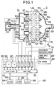
- FIGURE 1 is a schematic block diagram of a construction of an internal combustion gasoline engine (hereinafter, referred to simply as "engine") 2 to which the invention is applied, and a control system of the engine 2.
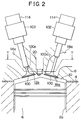
- FIGURE 2 is a longitudinal sectional view of the engine 2, taken on plane X-X in FIGURE 3.
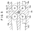
- FIGURE 3 is a sectional view of the engine 2, taken on plane Y-Y in FIGURE 2.
- the engine 2 is installed in a motor vehicle so as to drive the vehicle.
- the engine 2 has four cylinders 2a.
- Each cylinder 2a has a combustion chamber 10 that is defined by a cylinder block 4, a cylinder head 8 mounted on the cylinder block 4, and a piston 6 disposed inside the cylinder block 4 for reciprocating movements.
- Each combustion chamber 10 is provided with a first intake valve 12a, a second intake valve 12b, a first exhaust valve 16a and a second exhaust valve 16b.
- the valves 12a, 12b, 16a, 16b are formed as electromagnetically driven valves.
- the valves of each cylinder 2a are disposed so that the first intake valve 12a opens and closes a first intake port 14a, the second intake valve 12b opens and closes a second intake port 14b, the first exhaust valve 16a opens and closes a first exhaust port 18a, and the second exhaust valve 16b opens and closes a second exhaust port 18b.
- each intake port 14a and the second intake port 14b of each cylinder 2a are connected to a surge tank 32 via an intake passage 30a formed in an intake manifold 30.
- Each intake passage 30a is provided with a fuel injection valve 34 for injecting a needed amount of fuel into the first and second intake ports 14a and 14b.
- the surge tank 32 is connected to an air cleaner 42 via an intake duct 40.
- a throttle valve 46 that is driven by a motor 44 (a DC motor or a step motor) is disposed in the intake duct 40.
- the degree of opening of the throttle valve 46 (throttle opening TA) is detected by a throttle opening sensor 46a, and is controlled in accordance with operational conditions of the engine 2 and the operation of an accelerator pedal 74.
- the first exhaust port 18a and the second exhaust port 18b of each cylinder 2a are connected to an exhaust manifold 48, whereby exhaust gas is led to a catalytic converter 50 and then is released to the atmosphere.
- An electronic control unit (hereinafter, referred to as "ECU") 60 is formed by a digital computer equipped with a RAM (random access memory) 64, a ROM (read-only memory) 66, a CPU (microprocessor) 68, an input port 70, and an output port 72 that are interconnected by a bidirectional bus 62.
- a RAM random access memory
- ROM read-only memory
- CPU microprocessor
- the throttle opening sensor 46a for detecting the throttle opening TA outputs a voltage proportional to the degree of opening of the throttle valve 46, and the output voltage is inputted to the input port 70 via an A/D converter 73.
- the accelerator pedal 74 is provided with an accelerator depression sensor 76 that outputs a voltage proportional to the amount of depression of the accelerator pedal 74 (hereinafter, referred to as "accelerator depression ACCP").
- the output voltage of the accelerator depression sensor 76 is inputted to the input port 70 via an A/D converter 73.
- a top dead center sensor 80 generates an output pulse when, for example, the No. 1 cylinder of the cylinders 2a reaches the top dead center.
- the output pulse of the top dead center sensor 80 is inputted to the input port 70.
- a crank angle sensor 82 generates an output pulse every time a crankshaft turns 30°.
- the output pulse of the crank angle sensor 82 is inputted to the input port 70.
- the CPU 68 calculates a present crank angle.
- the CPU 68 calculates an engine revolution speed.
- the intake duct 40 is provided with an intake air amount sensor 84 that outputs a voltage corresponding to an amount of intake air GA flowing through the intake duct 40.
- the output voltage of the intake air amount sensor 84 is inputted to the input port 70 via an A/D converter 73.
- the cylinder block 4 of the engine 2 is provided with a water temperature senor 86 that detects the temperature THW of cooling water of the engine 2 and outputs a voltage in accordance with the cooling water temperature THW to the input port 70 via an A/D converter 73.
- the exhaust manifold 48 is provided with an air-fuel ratio sensor 88 that outputs a voltage in accordance with the air-fuel ratio, to the input port 70 via an A/D converter 73.
- the output port 72 is connected to the fuel injection valves 34 via a corresponding drive circuit 90.
- the ECU 60 performs a control of opening each fuel injection valve 34, and performs a fuel injection timing control and a fuel injection amount control.
- the output port 72 is also connected to the intake valves 12a, 12b and the exhaust valves 16a, 16b, via a drive circuit 92.
- the ECU 60 performs a control of opening the valves 12a, 12b, 16a, 16b, and performs an intake air amount control, an exhaust control, and an internal EGR control.
- the output port 72 is also connected to the motor 44 via a drive circuit 93.
- the ECU 60 controls the degree of opening of the throttle valve 46 in accordance with the operational condition of the engine 2 and the accelerator depression ACCP.
- FIGURE 4 illustrates an internal construction of the first exhaust valve 16a.
- the first exhaust valve 16a has a valve body 100, a valve shaft 100a extending from the valve body 100, and an electromagnetic drive unit 102.
- the valve shaft 100a has a lower retainer 104 that is fixed to an end portion of the valve shaft 100a opposite from the valves body 100.
- a compressed lower spring 106 is disposed between the lower retainer 104 and a spring support surface 8a that is formed on the cylinder head 8.
- the lower retainer 104 urges the valve body 100 and the valve shaft 100a in such a direction that the valve body 100 and the valve shaft 100a move away from the combustion chamber 10, that is, in such a direction that the valve body 100 closes the first exhaust port 18a.
- the electromagnetic drive unit 102 has, in a central portion thereof, an armature shaft 108 that extends coaxially with the valve shaft 100a.
- the armature shaft 108 has a high magnetic permeability material-made armature 110 that is fixed to a substantially central portion of the armature shaft 108, and an upper retainer 112 that is fixed to an end of the armature shaft 108.
- An end portion of the armature shaft 108 remote from the upper retainer 112 is in contact with an end portion of the valve shaft 100a closer to the lower retainer 104.
- An annular upper core 116 is fixed inside a casing 114 (FIGURE 2) of the electromagnetic drive unit 102, at a position between the upper retainer 112 and the armature 110, with the armature shaft 108 extending through the upper core 116.
- An annular lower core 118 is fixed inside the casing 114 of the electromagnetic drive unit 102, at a side of the armature 110 opposite from the upper core 116, with the armature shaft 108 extending through the lower core 118.
- the casing 114 is fixed to the cylinder head 8.
- the upper core 116 and the lower core 118 are supported slidably along the armature shaft 108 by bushes 116a, 118a each of which is provided in a central through-hole of the corresponding one of the upper core 116 and the lower core 118.
- a compressed upper spring 120 is disposed between the upper retainer 112 fixed to the upper end of the armature shaft 108 and an upper cap 114a provided in the casing 114.
- the upper spring 120 urges the armature shaft 108 to the valve shaft 100a. Therefore, the valve shaft 100a and the valve body 100 receive forces from the lower spring 106 and the upper spring 120 in opposite directions.
- the upper core 116 is formed from a high magnetic permeability material, and has an annular groove 116b that extends around the armature shaft 108 extending through the upper core 116 in a slidable manner.
- the annular groove 116b opens toward the armature 110.
- An exciting upper coil 122 is disposed in the annular groove 116b.
- the lower core 118 is formed from a high magnetic permeability material, and has an annular groove 118b that extends around the armature shaft 108 extending through the lower core 118 in a slidable manner.
- the annular groove 118b opens toward the armature 110.
- An exciting upper coil 124 is disposed in the annular groove 118b.
- FIGURE 4 shows a state in which neither the upper coil 122 nor the lower coil 124 is supplied with an exciting current.
- the armature 110 since the armature 110 is not magnetically attracted toward either the upper core 116 or the lower core 118, the armature shaft 108 and the valve shaft 100a exist at a position where the forces mainly from the upper spring 120 and the lower spring 106 balance each other.
- the valve body 100 is slightly apart from a valve seat 126, and the first exhaust port 18a is half open.
- the upper coil 122 When the upper coil 122 is supplied with an exciting current, the upper core 116 magnetized by the upper coil 122 attracts the armature 110. The attracting force moves the armature 110 to contact the upper core 116, overcoming the force from the upper spring 120.
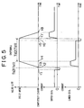
- the exciting current is reduced to a current that is needed to hold the armature 110 in position (hereinafter, referred to as "hold current"), as indicated in a portion preceding time point t1 in a timing chart in FIGURE 5 that indicates an operation of the first exhaust valve 16a.
- hold current a current that is needed to hold the armature 110 in position
- the attraction force from the upper core 116 that holds the armature 110 is quickly removed (time t1-t2) by supplying the upper coil 122 with a reverse current (hereinafter, referred to as "release current") opposite in direction to the hold current.
- release current a reverse current
- the current supplied to the upper coil 122 is changed to zero at time point t2.
- the armature 110 starts to move toward the lower core 118, that is, toward the fully open state, due to the force from the upper spring 120.
- the valve body 100 starts to separate from the valve seat 126, and the valve lift starts to increase.
- draw current a great current supplied to the lower coil 124 (time t3-t4) to draw the armature 110, which has been released from the upper core 116, until the armature 110 contacts the lower core 118.
- the armature 110 When the armature 110 contacts the lower core 118 (time point t4), the current is reduced to the hold current (time t4-t5). By holding the armature 110 in contact with the lower core 118 in this manner, the armature 110 is held in a state where the valve body 100 is farthest apart from the valve seat 126, that is, a fully open state. The operation of closing the first exhaust valve 16a from the fully open state will be described below.
- the hold current supplied to the lower coil 124 is changed to the release current (time point t5), whereby the attraction force of the lower core 118 holding the armature 110 is rapidly removed (time t5-t6).
- the current through the lower coil 124 is set to zero.
- the armature 110 starts to move toward the upper core 116, that is, toward the completely closed state, due to the force from the lower spring 106.
- the valve body 100 starts to move toward the valve seat 126, and the valve lift starts to decrease.
- the draw current is supplied to the upper coil 122 (time t7-t8).
- the armature 110 which has been released from the lower core 118, is drawn until the armature 110 contacts the upper core 116.
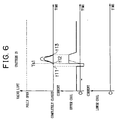
- a reduced valve lift of the first exhaust valve 16a can be achieved by using a drive method that is different from the above-described drive method.
- the drive method for achieving a reduced valve lift will be described with reference to the timing chart of FIGURE 6.
- the attraction force of the upper core 116 holding the armature 110 is rapidly diminished (time t11-t12).
- the armature 110 starts to move toward the lower core 118, that is, toward the fully open sate, due to the force from the upper spring 120.
- the valve body 100 starts to move apart from the valve seat 126, and the valve lift starts to increase.
- the current supplied to the upper core 116 is changed from the release current to the draw current (time point t12).
- the armature 110 which has moved apart from the upper core 116, is stopped in partway to the lower core 118, and is drawn back toward the upper core 116.
- the valve seat 126 which has moved apart from the valve seat 126, starts to move toward the valve seat 126. That is, during this operation, the valve lift temporarily increases, and then starts to decrease before it reaches a maximum lift (i.e., the fully open state).
- the current supplied to the upper core 116 is changed from the draw current to the hold current.
- a valve pattern in which the valve lift does not reach the maximum lift (the fully open state) is achieved as indicated in FIGURE 6, thereby realizing a very small internal EGR amount.
- the internal EGR amount achieved in this method can be adjusted as indicated by a one-dot chain line in FIGURE 6, by adjusting the rate of rise of the draw current at time point t12 or adjusting the magnitude of the draw current.
- pattern 1 a valve open/close pattern as indicated in FIGURE 5 which is followed by the first exhaust valve 16a and the second exhaust valve 16b for internal EGR while the combustion chamber 10 is expanding in capacity
- pattern 2 a valve open/close pattern as indicated in FIGURE 6 that is followed by the first exhaust valve 16a and the second exhaust valve 16b
- pattern 1 an internal EGR is determined by the length of time during which the armature 110 is held to the lower core 118 by the magnetic attraction force produced by the lower coil 124.
- pattern 2 an internal EGR amount is determined by the lift pattern followed by the valve body 100 during the operation of temporarily moving the valve body 100 apart from the valve seat 126 and then moving the valve body 100 back to the valve seat 126. Therefore, pattern 2 tends to allow a control range less than that of pattern 1, in which the valve body 100 is opened by the magnetic attraction force that is actively produced by the lower coil 124. Pattern 2 has this tendency probably because during a period between the release from the magnetic attraction and the return to the upper core 116 in pattern 2, the armature 110 temporarily undergoes a floating state, and therefore is susceptible to ambient conditions.
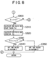
- FIGURES 7 and 8 are flowcharts illustrating an internal EGR control setting operation. This operation is executed periodically at every 180°CA (crank angle) provided that a condition for executing the internal EGR control is met. Steps in the flowcharts corresponding to various processings are indicated by "S".
- the ECU 60 When the internal EGR control setting operation is started, the ECU 60 first reads the engine revolution speed NE detected based on the signal from the crank angle sensor 82, and the load (more specifically, the intake air amount GA detected by the intake air amount sensor 84 in this embodiment) into a work area of the RAM 64 (S200).
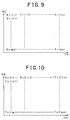
- the ECU 60 calculates a required EGR amount Er from the engine revolution speed NE and the intake air amount GA read in step S200, based on a map illustrated in FIGURE 9 (S210). To form this map, suitable EGR amounts corresponding to various operational conditions are empirically determined. Therefore, in the map, the EGR amount is determined in relation to the parameters of the engine revolution speed NE and the intake air amount GA. The map is pre-stored in the ROM 66.
- the ECU 60 determines whether the required EGR amount Er is greater than a recirculation amount criterion Es (S220).
- the recirculation amount criterion Es is a value used to determine whether the internal EGR control can be performed by using both the first exhaust valve 16a and the second exhaust valve 16b or must be performed by using only one of the first exhaust valve 16a and the second exhaust valve 16b in order to achieve a high precision in the internal EGR control. If both the first exhaust valve 16a and the second exhaust valve 16b were used to perform the internal EGR control in all the operational regions, the control based on pattern 2 could become necessary in the case of a relatively small required EGR amount Er.
- the control be based on pattern 1 as much as possible. Therefore, in order to increase the incidence of the control based on pattern 1, the required EGR amount Er is evaluated in magnitude by using the recirculation amount criterion Es, and it is accordingly determined whether to perform the internal EGR control using both the valves or the internal EGR control using only one of the two valves.
- the ECU 60 calculates an EGR start timing Ts2 for the internal EGR control performed by driving both the first exhaust valve 16a and the second exhaust valve 16b during the intake stroke (S230).
- the two-valve EGR start timing Ts2 is calculated, for example, based on a map indicated in FIGURE 10 that uses the engine revolution speed NE and the intake air amount GA as parameters. This map is empirically formed. That is, suitable two-valve EGR start timings Ts2 corresponding to various operational conditions are determined in experiments where the two exhaust valves 16a, 16b are driven. Therefore, in the map, the two-valve EGR start timing Ts2 is determined in relation to the parameters of the engine revolution speed NE and the intake air amount GA. The map is pre-stored in the ROM 66.
- the ECU 60 calculates an EGR duration Td2 for the internal EGR control performed by driving both the first exhaust valve 16a and the second exhaust valve 16b during the intake stroke (S240).
- the two-valve EGR duration Td2 is determined based on a map by using the required EGR amount Er determined in step S210 as a parameter. This map is set by empirically determining suitable two-valve EGR durations Td2 corresponding to required EGR amounts Er in experiments where the two exhaust valves 16a, 16b are driven. The map is pre-stored in the ROM 66.
- the ECU 60 sets the information of "two-valve drive in pattern 1" as control data to be used in an exhaust valve driving routine (not shown) (S250), in order to perform the internal EGR control during the intake stroke.
- the information of "two-valve drive in pattern 1" indicates a control in which the first exhaust valve 16a and the second exhaust valve 16b are both driven based on pattern 1 (FIGURE 5). Subsequently, the ECU 60 temporarily ends this routine.
- the ECU 60 When the internal EGR control is set to the "two-valve drive in pattern 1" mode, the ECU 60, in the exhaust valve driving routine, controls the currents supplied to the upper coils 122 and the lower coils 124 of the first exhaust valve 16a and the second exhaust valve 16b in accordance with the two-valve EGR start timing Ts2 and the two-valve EGR duration Td2 during the intake stroke as indicated in FIGURE 5.
- step S220 If it is determined in step S220 that Er ⁇ Es (NO in S220), it is considered that the driving of the two exhaust valves 16a, 16b will not allow the open/close operation based on pattern 1. Therefore, the process proceeds to step S300.
- the ECU 60 calculates an EGR start timing Ts1 for the internal EGR control performed by driving one of the first exhaust valve 16a and the second exhaust valve 16b (e.g., the first exhaust valve 16a in this embodiment) during the intake stroke (S310).
- the one-valve EGR start timing Ts1 is calculated, for example, based on a map indicated in FIGURE 11 that uses the engine revolution speed NE and the intake air amount GA as parameters. This map is empirically formed. That is, suitable one-valve EGR start timings Ts1 corresponding to various operational conditions are determined in experiments where only the first exhaust valve 16a is driven. Therefore, in the map, the one-valve EGR start timing Ts1 is determined in relation to the parameters of the engine revolution speed NE and the intake air amount GA. The map is pre-stored in the ROM 66.
- the ECU 60 calculates an EGR duration Td1 for the internal EGR control performed by driving only the first exhaust valve 16a during the intake stroke (S320).
- the one-valve EGR duration Td1 is determined based on a map by using the required EGR amount Er determined in step S210 as a parameter. This map is set by empirically determining suitable one-valve EGR durations Td1 corresponding to required EGR amounts Er in experiments where only the first exhaust valve 16a is driven. The map is pre-stored in the ROM 66.
- the ECU 60 determines whether the one-valve EGR duration Td1 is greater than a criterion a (S330).
- the criterion a is a value used to determine a situation where the changing of the current and the direction of current for achieving pattern 1 becomes difficult or impossible due to a very small one-valve EGR duration Td1 even though only one of the two exhaust valves is driven.
- the ECU 60 sets the information of "one-valve drive in pattern 1" as control data to be used in the exhaust valve driving routine (S340), in order to perform the internal EGR control during the intake stroke.
- the information of "one-valve drive in pattern 1" indicates a control in which the first exhaust valve 16a is driven based on pattern 1 (FIGURE 5) but the second exhaust valve 16b is not driven. Subsequently, the ECU 60 temporarily ends this routine.
- the ECU 60 drives only the first exhaust valve 16a in a pattern as indicated in FIGURE 5 during the intake stroke in the exhaust valve driving routine. More specifically, the ECU 60 sets a one-valve EGR start timing Ts1 and a one-valve EGR duration Td1, instead of the two-valve EGR start timing Ts2 and the two-valve EGR duration Td2, and controls the currents supplied to the upper coil 122 and the lower coil 124 as indicated in FIGURE 5.
- step S330 If it is determined in step S330 that Td1 ⁇ a (NO in S330), the ECU 60 sets the information of "one-valve drive in pattern 2" as control data to be used in the exhaust valve driving routine (S350), in order to perform the internal EGR control during the intake stroke.
- the information of "one-valve drive in pattern 2" indicates a control in which the first exhaust valve 16a is driven based on pattern 2 (FIGURE 6) but the second exhaust valve 16b is not driven. In pattern 2, the one-valve EGR duration Td1 does not exist.
- a control of the current supplied to the upper coil 122 that corresponds to the control based on the one-valve EGR duration Td1 is achieved by adjusting the rising rate of current as indicated by the one-dot chain line in FIGURE 6 or adjusting the magnitude of current. It is also possible to omit a control corresponding to the control based on the one-valve EGR duration Td1 and perform the control of current supplied to the upper coil 122 in a constant pattern, since the control range in pattern 2 is relatively narrow.
- the ECU 60 temporarily ends the routine.
- the ECU 60 drives only the first exhaust valve 16a in the pattern indicated in FIGURE 6 during the intake stroke by controlling the current supplied to the upper coil 122 in the exhaust gas driving routine.
- step S210 corresponds to a process performed by an exhaust gas recirculation amount calculating means
- steps S220 to S350 correspond to a process performed by an exhaust valve driving means.
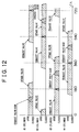
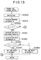
- the second embodiment differs from the first embodiment in that the second embodiment performs an internal EGR control setting operation illustrated in FIGURE 13, instead of the internal EGR control setting operation illustrated in FIGURES 7 and 8.
- Other constructions and operations of the second embodiment are substantially the same as those of the first embodiment.
- the steps having substantially the same contents as those in the first embodiment are represented by reference numerals obtained by adding "1000" to the corresponding numerals used in FIGURES 8 and 9, unless otherwise mentioned.
- step S1210 is immediately followed by step S1300. That is, the second exhaust gas recirculation mode (steps S230 to S250) is omitted, and only the first exhaust gas recirculation mode (steps S1310 to S1350) is adopted.
- steps S1310 to S1350 correspond to a process performed by an exhaust valve driving means.
- a third embodiment of the invention will be described.
- the third embodiment performs a control as described below, by utilizing constructions of the first and second embodiments.
- the ECU 60 periodically executes an intake valve driving mode setting operation as illustrated in the flowchart of FIGURE 14 in a predetermined cycle, that is, at every 180°CA. Steps in the flowchart of FIGURE 14 corresponding to processings are represented by "S".
- the ECU 60 When the intake valve driving mode setting operation is started, the ECU 60 reads the detection values of the engine revolution speed NE and the load (e.g., the intake air amount GA in this embodiment) into a work area of the RAM 64 (S1400). Subsequently, the ECU 60 determines whether the engine operation is in a low-speed and low-load condition by comparing the detection values NE, GA with their respective thresholds (S1410).
- the detection values of the engine revolution speed NE and the load e.g., the intake air amount GA in this embodiment
- the ECU 60 If the engine operation is in the low-speed and low-load condition (YES in S1410), the ECU 60 enters a first intake mode in which the second intake valve 12b is not driven but the first intake valve 12a alone is driven to reduce the electric power for driving the valves (S1420). If the engine operation is not in the low-speed and low-load condition (NO in S1410), the ECU 60 enters a second intake mode in which the two intake valves 12a, 12b are driven, that is, the normal valve driving is performed (S1430). After step S1420 or step S1430 ends, the ECU 60 temporarily ends the intake valve driving mode setting operation.
- the ECU 60 also executes the internal EGR control setting operation as in the first or second embodiment.
- the second exhaust valve 16b is selected as an object to be driven during the first exhaust gas recirculation mode (steps S310 to S350 or steps S1310 to S1350). That is, the second exhaust valve 16b disposed diagonally opposite from the first intake valve 12a, which is opened during the first intake mode, is selected as an object to be driven during the internal EGR control.
- the intake valve driving mode setting operation illustrated in FIGURE 14 corresponds to a process performed by an intake valve driving means in the invention.
- the third embodiment achieves the following advantages.
- the electromagnetic drive unit 102 is of a type in which no permanent magnet is disposed in the upper core 116 or the lower core 118.
- the invention is also applicable to a construction having electromagnetic drive units in which a permanent magnet is disposed in at least one of an upper core and a lower core.
- the internal combustion engine is a gasoline engine
- the invention is also applicable to a diesel engine in substantially the same manner.
- the intake air amount is adjusted by the throttle valve 46
- the invention is also applicable to an engine system in which a throttle valve is not disposed in an intake duct 40 but the intake air amount can be adjusted by intake valves 12a, 12b.
- maps as indicated in FIGURES 9 to 11 may be formed by using the accelerator depression ACCP instead of the engine revolution speed NE.
- the exhaust valves 16a, 16b are driven in a valve drive mode suitably selected from the three modes, that is, the "two-valve drive in pattern 1" mode, the "one-valve drive in pattern 1" mode, and the “one-valve drive in pattern 2" mode, based on the magnitude of the required EGR amount Er, and the like.
- the valve drive mode may also be changed among four modes including the aforementioned three modes and a "two-valve drive in pattern 2" mode.
- the valve drive mode may be changed sequentially in the order of the "two-valve drive in pattern 1" mode, the "one-valve drive in pattern 1", the “two-valve drive in pattern 2" mode, and the "one-valve drive in pattern 2" mode.
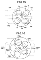
- an exhaust valve disposed diagonally opposite from an intake valve used as an object to be driven during the first intake mode is set as an object to be driven during the first exhaust gas recirculation mode, while a combination of two intake valves and two exhaust valves is adopted.
- the invention is also applicable to a combination of three intake valves 152a, 152b, 152c and two exhaust valves 156a, 156b as shown in FIGURE 16. If an exhaust valve 156b disposed diagonally opposite from an intake valve 152a used as an object to be driven during the first intake mode is set as an object to be driven during the first exhaust gas recirculation mode, the formation of swirls is promoted and the combustibility improves as in the third embodiment.
- a first exhaust gas recirculation mode is entered by driving only a first exhaust valve of each cylinder.
- An open valve duration Td1 for achieving the required EGR amount Er in a one-valve drive manner is longer than a corresponding open valve duration in a two-valve drive manner. Therefore, even if the required EGR amount Er is small, a "one-valve drive in pattern 1" mode can be achieved provided that Td1 > a. That is, the incidence of performing the control in pattern 2, which allows only a narrow range of control, can be reduced. Hence, degradation of controllability can be prevented even if the required EGR amount Er is small.
Landscapes
- Engineering & Computer Science (AREA)
- Mechanical Engineering (AREA)
- General Engineering & Computer Science (AREA)
- Chemical & Material Sciences (AREA)
- Combustion & Propulsion (AREA)
- Physics & Mathematics (AREA)
- Electromagnetism (AREA)
- Output Control And Ontrol Of Special Type Engine (AREA)
- Valve Device For Special Equipments (AREA)
- Exhaust-Gas Circulating Devices (AREA)
Abstract
Description
Claims (7)
- A valve driving apparatus for an internal combustion engine including a plurality of electromagnetically operated exhaust valves (16a, 16b) for each cylinder of the engine, the plurality of exhaust valves including a least one first exhaust valve (16a) and a least one second exhaust valve (16b), the valve driving apparatus characterized by comprising an exhaust valve driving means (S220∼S350, S1310∼S1350) for, in a first exhaust gas recirculation mode when exhaust gas recirculation is performed independently of an exhaust stroke, driving the at least one first exhaust valve (16a) and does not drive the at least one second exhaust valve (16b).
- A valve driving apparatus for an internal combustion engine according to claim 1, characterized by further comprising an exhaust gas recirculation amount calculating means (S210) for determining a required exhaust gas recirculation amount in accordance with an operational condition of the engine,and in that the exhaust valve driving means (S220∼ S350) operates exhaust gas recirculation under the first mode when the required exhaust gas recirculation amount (Er) is less than a recirculation amount criterion and in that, when the required exhaust gas recirculation amount (Er) is greater than the recirculation amount criterion, the exhaust valve driving means (S220∼S350) operates under a second exhaust gas recirculation mode exhaust gas recirculation driving all of the exhaust valves (16a,16b).
- A valve driving apparatus for an internal combustion engine according to claim 2, characterized in that an amount of lift by which the exhaust valve driving means (s220∼s350) moves the exhaust valves is determined based on a quantity related to the required exhaust gas recirculation amount (Er).
- A valve driving apparatus for an internal combustion engine according to claim 3, characterized in that the quantity related to the required exhaust gas recirculation amount (Er) is a required control duration for performing the exhaust gas recirculation.
- A valve driving apparatus for an internal combustion engine according to claim 4, characterized in that when the required exhaust gas recirculation amount (Er) is less than the recirculation amount criterion and the required control duration (Td1) is greater than a predetermined threshold, the exhaust valve driving means (S220 ∼ S350) moves only the at least one first exhaust valve (16a) to a fully open state and wherein, when the required exhaust gas recirculation amount (Er) is less than the recirculation amount criterion and the required control duration (Td1) is less than the predetermined threshold, the exhaust valve driving means (S220∼S350) moves only the at least one first exhaust valve (16a) in a valve opening direction and then moves the at least one first exhaust valve (16a) in a valve closing direction before the at least one first exhaust valve reach the fully open state.
- A valve driving apparatus for an internal combustion engine as claimed in any of claims 1 to 5, characterized in that the engine includes a plurality of intake valves (12a, 12b) for each cylinder of the engine, the plurality of intake valves including at least one first intake valve (12a) and at least one second intake valve (12b), the valve driving apparatus characterized by further comprising an intake valve driving means (s1400∼s1430) for, in a first intake mode, driving the at least one first intake valve (12a) for each cylinder and does not drive the at least one second intake valve (12b) for each cylinder and for, in a second intake mode, driving all of the intake valves (12a, 12b), the intake valve driving means (S1400∼ S1430) for switching between the first and second intake modes based on an operational condition of the engine,and in that the exhaust valve driving means (S1400∼ S1430) selects, as one of the first exhaust valves for each cylinder, an exhaust valve positioned to promote a swirl in a combustion chamber during the first intake mode.
- A valve driving apparatus for an internal combustion engine according to claim 6, characterized in that each cylinder is provided with two intake valves (12a, 12b) and two exhaust valves (16a, 16b), and in that the exhaust valve driving means (S1310∼S1350) selects, as one of the first exhaust valves for each cylinder, an exhaust valve disposed diagonally opposite from an intake valve selected as one of the first intake valves for the corresponding cylinder.
Applications Claiming Priority (2)
| Application Number | Priority Date | Filing Date | Title |
|---|---|---|---|
| JP19740399A JP3994586B2 (en) | 1999-07-12 | 1999-07-12 | Valve driving device for internal combustion engine |
| JP19740399 | 1999-07-12 |
Publications (3)
| Publication Number | Publication Date |
|---|---|
| EP1069283A2 true EP1069283A2 (en) | 2001-01-17 |
| EP1069283A3 EP1069283A3 (en) | 2002-11-27 |
| EP1069283B1 EP1069283B1 (en) | 2006-08-23 |
Family
ID=16373941
Family Applications (1)
| Application Number | Title | Priority Date | Filing Date |
|---|---|---|---|
| EP00114846A Expired - Lifetime EP1069283B1 (en) | 1999-07-12 | 2000-07-11 | Valve driving apparatus for internal combustion engine |
Country Status (4)
| Country | Link |
|---|---|
| US (1) | US6374813B1 (en) |
| EP (1) | EP1069283B1 (en) |
| JP (1) | JP3994586B2 (en) |
| DE (1) | DE60030216T2 (en) |
Cited By (3)
| Publication number | Priority date | Publication date | Assignee | Title |
|---|---|---|---|---|
| DE10338663A1 (en) * | 2003-08-22 | 2005-03-17 | Audi Ag | Engine system has controlled actuators to adjust valve cam to vary the valve stroke and timing |
| FR2859765A1 (en) * | 2003-09-15 | 2005-03-18 | Renault Sa | SYSTEM AND METHOD FOR EXHAUST GAS RECIRCULATION FOR INTERNAL COMBUSTION ENGINE |
| WO2005113965A1 (en) * | 2004-05-10 | 2005-12-01 | Daimlerchrysler Ag | Device with a unit for actuating at least one exhaust valve |
Families Citing this family (39)
| Publication number | Priority date | Publication date | Assignee | Title |
|---|---|---|---|---|
| JP2002180894A (en) * | 2000-12-12 | 2002-06-26 | Toyota Motor Corp | Control device for internal combustion engine |
| JP3900081B2 (en) * | 2002-12-17 | 2007-04-04 | トヨタ自動車株式会社 | In-cylinder inflow exhaust gas amount calculation device for internal combustion engine and inflow exhaust gas amount calculation device for intake passage |
| US7004124B2 (en) * | 2003-07-01 | 2006-02-28 | General Motors Corporation | Valve strategy for operating a controlled auto-ignition four-stroke internal combustion engine |
| US6871617B1 (en) | 2004-01-09 | 2005-03-29 | Ford Global Technologies, Llc | Method of correcting valve timing in engine having electromechanical valve actuation |
| US7555896B2 (en) * | 2004-03-19 | 2009-07-07 | Ford Global Technologies, Llc | Cylinder deactivation for an internal combustion engine |
| US7240663B2 (en) * | 2004-03-19 | 2007-07-10 | Ford Global Technologies, Llc | Internal combustion engine shut-down for engine having adjustable valves |
| US7559309B2 (en) * | 2004-03-19 | 2009-07-14 | Ford Global Technologies, Llc | Method to start electromechanical valves on an internal combustion engine |
| US7032545B2 (en) * | 2004-03-19 | 2006-04-25 | Ford Global Technologies, Llc | Multi-stroke cylinder operation in an internal combustion engine |
| US7128043B2 (en) | 2004-03-19 | 2006-10-31 | Ford Global Technologies, Llc | Electromechanically actuated valve control based on a vehicle electrical system |
| US7031821B2 (en) * | 2004-03-19 | 2006-04-18 | Ford Global Technologies, Llc | Electromagnetic valve control in an internal combustion engine with an asymmetric exhaust system design |
| US6938598B1 (en) | 2004-03-19 | 2005-09-06 | Ford Global Technologies, Llc | Starting an engine with electromechanical valves |
| US7140355B2 (en) * | 2004-03-19 | 2006-11-28 | Ford Global Technologies, Llc | Valve control to reduce modal frequencies that may cause vibration |
| US7072758B2 (en) * | 2004-03-19 | 2006-07-04 | Ford Global Technologies, Llc | Method of torque control for an engine with valves that may be deactivated |
| US7079935B2 (en) * | 2004-03-19 | 2006-07-18 | Ford Global Technologies, Llc | Valve control for an engine with electromechanically actuated valves |
| US7383820B2 (en) * | 2004-03-19 | 2008-06-10 | Ford Global Technologies, Llc | Electromechanical valve timing during a start |
| US7055483B2 (en) * | 2004-03-19 | 2006-06-06 | Ford Global Technologies, Llc | Quick starting engine with electromechanical valves |
| US7021289B2 (en) * | 2004-03-19 | 2006-04-04 | Ford Global Technology, Llc | Reducing engine emissions on an engine with electromechanical valves |
| US7107946B2 (en) * | 2004-03-19 | 2006-09-19 | Ford Global Technologies, Llc | Electromechanically actuated valve control for an internal combustion engine |
| US7063062B2 (en) * | 2004-03-19 | 2006-06-20 | Ford Global Technologies, Llc | Valve selection for an engine operating in a multi-stroke cylinder mode |
| US7194993B2 (en) * | 2004-03-19 | 2007-03-27 | Ford Global Technologies, Llc | Starting an engine with valves that may be deactivated |
| US7107947B2 (en) * | 2004-03-19 | 2006-09-19 | Ford Global Technologies, Llc | Multi-stroke cylinder operation in an internal combustion engine |
| US7165391B2 (en) | 2004-03-19 | 2007-01-23 | Ford Global Technologies, Llc | Method to reduce engine emissions for an engine capable of multi-stroke operation and having a catalyst |
| US7017539B2 (en) * | 2004-03-19 | 2006-03-28 | Ford Global Technologies Llc | Engine breathing in an engine with mechanical and electromechanical valves |
| US7028650B2 (en) * | 2004-03-19 | 2006-04-18 | Ford Global Technologies, Llc | Electromechanical valve operating conditions by control method |
| US7066121B2 (en) * | 2004-03-19 | 2006-06-27 | Ford Global Technologies, Llc | Cylinder and valve mode control for an engine with valves that may be deactivated |
| US7032581B2 (en) * | 2004-03-19 | 2006-04-25 | Ford Global Technologies, Llc | Engine air-fuel control for an engine with valves that may be deactivated |
| US7128687B2 (en) * | 2004-03-19 | 2006-10-31 | Ford Global Technologies, Llc | Electromechanically actuated valve control for an internal combustion engine |
| JP4254614B2 (en) * | 2004-05-18 | 2009-04-15 | 株式会社豊田自動織機 | Premixed compression ignition engine |
| US7152559B2 (en) * | 2004-07-26 | 2006-12-26 | General Motors Corporation | Valve and fueling strategy for operating a controlled auto-ignition four-stroke internal combustion engine |
| US7128047B2 (en) * | 2004-07-26 | 2006-10-31 | General Motors Corporation | Valve and fueling strategy for operating a controlled auto-ignition four-stroke internal combustion engine |
| US7150250B2 (en) * | 2004-07-26 | 2006-12-19 | General Motors Corporation | Valve and fueling strategy for operating a controlled auto-ignition four-stroke internal combustion engine |
| US7089895B2 (en) * | 2005-01-13 | 2006-08-15 | Motorola, Inc. | Valve operation in an internal combustion engine |
| US7458345B2 (en) * | 2005-04-15 | 2008-12-02 | Ford Global Technologies, Llc | Adjusting ballistic valve timing |
| JP2007315293A (en) * | 2006-05-25 | 2007-12-06 | Toyota Motor Corp | Valve control device for internal combustion engine |
| US7832370B2 (en) * | 2006-11-16 | 2010-11-16 | Gm Global Technology Operations, Inc. | Low-load operation extension of a homogeneous charge compression ignition engine |
| US7565899B2 (en) * | 2007-06-12 | 2009-07-28 | Ford Global Technologies, Llc | Engine fueling control during cylinder valve mode transitions |
| DE102007037333A1 (en) * | 2007-08-08 | 2009-02-26 | Daimler Ag | actuator |
| JP2013087628A (en) * | 2011-10-13 | 2013-05-13 | Mitsubishi Motors Corp | Engine with exhaust gas recirculating device |
| GB2570335B (en) * | 2018-01-22 | 2020-03-11 | Ford Global Tech Llc | An exhaust gas recirculation valve control method |
Citations (1)
| Publication number | Priority date | Publication date | Assignee | Title |
|---|---|---|---|---|
| JPH02294547A (en) | 1989-05-09 | 1990-12-05 | Isuzu Motors Ltd | Exhaust gas recirculating flow rate detecting device for engine and exhaust gas recirculating flow rate control device |
Family Cites Families (5)
| Publication number | Priority date | Publication date | Assignee | Title |
|---|---|---|---|---|
| US5203830A (en) * | 1992-06-01 | 1993-04-20 | Caterpillar Inc. | Method and apparatus to reduce engine combustion noise utilizing unit valve actuation |
| GB9222353D0 (en) * | 1992-10-23 | 1992-12-09 | Ricardo Consulting Eng | Spark ignited internal combustion engines |
| GB2301398B (en) * | 1994-03-07 | 1998-01-14 | Komatsu Mfg Co Ltd | Variable compression ratio engine |
| DE59705848D1 (en) * | 1996-06-20 | 2002-01-31 | Volkswagen Ag | Method and device for operating a spark-ignition reciprocating internal combustion engine |
| GB2328975A (en) * | 1997-09-03 | 1999-03-10 | Ford Global Tech Inc | Combustion engine with internal EGR |
-
1999
- 1999-07-12 JP JP19740399A patent/JP3994586B2/en not_active Expired - Fee Related
-
2000
- 2000-07-11 EP EP00114846A patent/EP1069283B1/en not_active Expired - Lifetime
- 2000-07-11 DE DE60030216T patent/DE60030216T2/en not_active Expired - Fee Related
- 2000-07-12 US US09/614,609 patent/US6374813B1/en not_active Expired - Fee Related
Patent Citations (1)
| Publication number | Priority date | Publication date | Assignee | Title |
|---|---|---|---|---|
| JPH02294547A (en) | 1989-05-09 | 1990-12-05 | Isuzu Motors Ltd | Exhaust gas recirculating flow rate detecting device for engine and exhaust gas recirculating flow rate control device |
Cited By (4)
| Publication number | Priority date | Publication date | Assignee | Title |
|---|---|---|---|---|
| DE10338663A1 (en) * | 2003-08-22 | 2005-03-17 | Audi Ag | Engine system has controlled actuators to adjust valve cam to vary the valve stroke and timing |
| DE10338663B4 (en) * | 2003-08-22 | 2009-01-02 | Audi Ag | Control unit of an actuator having device |
| FR2859765A1 (en) * | 2003-09-15 | 2005-03-18 | Renault Sa | SYSTEM AND METHOD FOR EXHAUST GAS RECIRCULATION FOR INTERNAL COMBUSTION ENGINE |
| WO2005113965A1 (en) * | 2004-05-10 | 2005-12-01 | Daimlerchrysler Ag | Device with a unit for actuating at least one exhaust valve |
Also Published As
| Publication number | Publication date |
|---|---|
| DE60030216T2 (en) | 2007-07-12 |
| DE60030216D1 (en) | 2006-10-05 |
| EP1069283A3 (en) | 2002-11-27 |
| JP3994586B2 (en) | 2007-10-24 |
| JP2001020767A (en) | 2001-01-23 |
| US6374813B1 (en) | 2002-04-23 |
| EP1069283B1 (en) | 2006-08-23 |
Similar Documents
| Publication | Publication Date | Title |
|---|---|---|
| EP1069283B1 (en) | Valve driving apparatus for internal combustion engine | |
| US6425369B2 (en) | Control apparatus for internal combustion engines | |
| JP4015889B2 (en) | EGR control device for internal combustion engine | |
| EP0867602B1 (en) | Electromagnetically operated valve control system and the method thereof | |
| US6612291B2 (en) | Fuel injection controlling system for a diesel engine | |
| US6817349B2 (en) | Control system and method and engine control unit for compression ignition internal combustion engine | |
| US6202608B1 (en) | Control system for internal combustion engine | |
| US6640756B2 (en) | Electromagnetic valve controller of an internal combustion engine | |
| US8874353B2 (en) | Device and method for controlling internal combustion engine | |
| CN102678359A (en) | Method for controlling an engine | |
| SE520407C2 (en) | Control device for a direct-injected, spark-plugged internal combustion engine | |
| US4757683A (en) | Exhaust gas recirculation method for internal combustion engines | |
| US6276317B1 (en) | Control apparatus and method for electromagnetically driven valves | |
| US7004125B2 (en) | Valve train system of internal combustion engine and control method thereof | |
| JP4151268B2 (en) | Stop control device for internal combustion engine with electromagnetically driven valve | |
| US20210156318A1 (en) | Internal combustion engine control method and internal combustion engine control device | |
| JP3510044B2 (en) | Starting method of electromagnetically driven valve of internal combustion engine | |
| JPH11223137A (en) | Inlet and exhaust valve control device for Miller cycle engine | |
| US6539901B2 (en) | Internal combustion engine having an electromagnetic valve drive mechanism and method for controlling the same | |
| JP2022150467A (en) | engine system | |
| JP2011106330A (en) | Control system for internal combustion engine | |
| JP2001159350A (en) | Engine fuel pressure control device | |
| JP3341555B2 (en) | Multi-stage opening valve control device for exhaust gas recirculation device | |
| JP2001020766A (en) | Valve drive for internal combustion engine | |
| WO2025258199A1 (en) | Fuel injection control device and fuel injection control method |
Legal Events
| Date | Code | Title | Description |
|---|---|---|---|
| PUAI | Public reference made under article 153(3) epc to a published international application that has entered the european phase |
Free format text: ORIGINAL CODE: 0009012 |
|
| 17P | Request for examination filed |
Effective date: 20000711 |
|
| AK | Designated contracting states |
Kind code of ref document: A2 Designated state(s): AT BE CH CY DE DK ES FI FR GB GR IE IT LI LU MC NL PT SE |
|
| AX | Request for extension of the european patent |
Free format text: AL;LT;LV;MK;RO;SI |
|
| PUAL | Search report despatched |
Free format text: ORIGINAL CODE: 0009013 |
|
| AK | Designated contracting states |
Kind code of ref document: A3 Designated state(s): AT BE CH CY DE DK ES FI FR GB GR IE IT LI LU MC NL PT SE |
|
| AX | Request for extension of the european patent |
Free format text: AL;LT;LV;MK;RO;SI |
|
| AKX | Designation fees paid |
Designated state(s): DE FR GB |
|
| GRAP | Despatch of communication of intention to grant a patent |
Free format text: ORIGINAL CODE: EPIDOSNIGR1 |
|
| GRAS | Grant fee paid |
Free format text: ORIGINAL CODE: EPIDOSNIGR3 |
|
| GRAA | (expected) grant |
Free format text: ORIGINAL CODE: 0009210 |
|
| AK | Designated contracting states |
Kind code of ref document: B1 Designated state(s): DE FR GB |
|
| REG | Reference to a national code |
Ref country code: GB Ref legal event code: FG4D |
|
| REF | Corresponds to: |
Ref document number: 60030216 Country of ref document: DE Date of ref document: 20061005 Kind code of ref document: P |
|
| ET | Fr: translation filed | ||
| PLBE | No opposition filed within time limit |
Free format text: ORIGINAL CODE: 0009261 |
|
| STAA | Information on the status of an ep patent application or granted ep patent |
Free format text: STATUS: NO OPPOSITION FILED WITHIN TIME LIMIT |
|
| 26N | No opposition filed |
Effective date: 20070524 |
|
| PGFP | Annual fee paid to national office [announced via postgrant information from national office to epo] |
Ref country code: FR Payment date: 20090710 Year of fee payment: 10 |
|
| PGFP | Annual fee paid to national office [announced via postgrant information from national office to epo] |
Ref country code: DE Payment date: 20090709 Year of fee payment: 10 Ref country code: GB Payment date: 20090708 Year of fee payment: 10 |
|
| GBPC | Gb: european patent ceased through non-payment of renewal fee |
Effective date: 20100711 |
|
| REG | Reference to a national code |
Ref country code: FR Ref legal event code: ST Effective date: 20110331 |
|
| PG25 | Lapsed in a contracting state [announced via postgrant information from national office to epo] |
Ref country code: DE Free format text: LAPSE BECAUSE OF NON-PAYMENT OF DUE FEES Effective date: 20110201 |
|
| REG | Reference to a national code |
Ref country code: DE Ref legal event code: R119 Ref document number: 60030216 Country of ref document: DE Effective date: 20110201 |
|
| PG25 | Lapsed in a contracting state [announced via postgrant information from national office to epo] |
Ref country code: FR Free format text: LAPSE BECAUSE OF NON-PAYMENT OF DUE FEES Effective date: 20100802 |
|
| PG25 | Lapsed in a contracting state [announced via postgrant information from national office to epo] |
Ref country code: GB Free format text: LAPSE BECAUSE OF NON-PAYMENT OF DUE FEES Effective date: 20100711 |