EP1069279B1 - Klappenventil mit Schliessunterstützung - Google Patents
Klappenventil mit Schliessunterstützung Download PDFInfo
- Publication number
- EP1069279B1 EP1069279B1 EP20000305885 EP00305885A EP1069279B1 EP 1069279 B1 EP1069279 B1 EP 1069279B1 EP 20000305885 EP20000305885 EP 20000305885 EP 00305885 A EP00305885 A EP 00305885A EP 1069279 B1 EP1069279 B1 EP 1069279B1
- Authority
- EP
- European Patent Office
- Prior art keywords
- flapper
- closure plate
- valve
- flapper closure
- connection member
- Prior art date
- Legal status (The legal status is an assumption and is not a legal conclusion. Google has not performed a legal analysis and makes no representation as to the accuracy of the status listed.)
- Expired - Lifetime
Links
Images


Classifications
-
- E—FIXED CONSTRUCTIONS
- E21—EARTH OR ROCK DRILLING; MINING
- E21B—EARTH OR ROCK DRILLING; OBTAINING OIL, GAS, WATER, SOLUBLE OR MELTABLE MATERIALS OR A SLURRY OF MINERALS FROM WELLS
- E21B34/00—Valve arrangements for boreholes or wells
- E21B34/06—Valve arrangements for boreholes or wells in wells
- E21B34/10—Valve arrangements for boreholes or wells in wells operated by control fluid supplied from outside the borehole
-
- F—MECHANICAL ENGINEERING; LIGHTING; HEATING; WEAPONS; BLASTING
- F16—ENGINEERING ELEMENTS AND UNITS; GENERAL MEASURES FOR PRODUCING AND MAINTAINING EFFECTIVE FUNCTIONING OF MACHINES OR INSTALLATIONS; THERMAL INSULATION IN GENERAL
- F16K—VALVES; TAPS; COCKS; ACTUATING-FLOATS; DEVICES FOR VENTING OR AERATING
- F16K15/00—Check valves
- F16K15/02—Check valves with guided rigid valve members
- F16K15/03—Check valves with guided rigid valve members with a hinged closure member or with a pivoted closure member
- F16K15/033—Check valves with guided rigid valve members with a hinged closure member or with a pivoted closure member spring-loaded
-
- E—FIXED CONSTRUCTIONS
- E21—EARTH OR ROCK DRILLING; MINING
- E21B—EARTH OR ROCK DRILLING; OBTAINING OIL, GAS, WATER, SOLUBLE OR MELTABLE MATERIALS OR A SLURRY OF MINERALS FROM WELLS
- E21B2200/00—Special features related to earth drilling for obtaining oil, gas or water
- E21B2200/05—Flapper valves
-
- Y—GENERAL TAGGING OF NEW TECHNOLOGICAL DEVELOPMENTS; GENERAL TAGGING OF CROSS-SECTIONAL TECHNOLOGIES SPANNING OVER SEVERAL SECTIONS OF THE IPC; TECHNICAL SUBJECTS COVERED BY FORMER USPC CROSS-REFERENCE ART COLLECTIONS [XRACs] AND DIGESTS
- Y10—TECHNICAL SUBJECTS COVERED BY FORMER USPC
- Y10T—TECHNICAL SUBJECTS COVERED BY FORMER US CLASSIFICATION
- Y10T137/00—Fluid handling
- Y10T137/7722—Line condition change responsive valves
- Y10T137/7837—Direct response valves [i.e., check valve type]
- Y10T137/7854—In couplings for coaxial conduits, e.g., drill pipe check valves
-
- Y—GENERAL TAGGING OF NEW TECHNOLOGICAL DEVELOPMENTS; GENERAL TAGGING OF CROSS-SECTIONAL TECHNOLOGIES SPANNING OVER SEVERAL SECTIONS OF THE IPC; TECHNICAL SUBJECTS COVERED BY FORMER USPC CROSS-REFERENCE ART COLLECTIONS [XRACs] AND DIGESTS
- Y10—TECHNICAL SUBJECTS COVERED BY FORMER USPC
- Y10T—TECHNICAL SUBJECTS COVERED BY FORMER US CLASSIFICATION
- Y10T137/00—Fluid handling
- Y10T137/7722—Line condition change responsive valves
- Y10T137/7837—Direct response valves [i.e., check valve type]
- Y10T137/7898—Pivoted valves
-
- Y—GENERAL TAGGING OF NEW TECHNOLOGICAL DEVELOPMENTS; GENERAL TAGGING OF CROSS-SECTIONAL TECHNOLOGIES SPANNING OVER SEVERAL SECTIONS OF THE IPC; TECHNICAL SUBJECTS COVERED BY FORMER USPC CROSS-REFERENCE ART COLLECTIONS [XRACs] AND DIGESTS
- Y10—TECHNICAL SUBJECTS COVERED BY FORMER USPC
- Y10T—TECHNICAL SUBJECTS COVERED BY FORMER US CLASSIFICATION
- Y10T137/00—Fluid handling
- Y10T137/7722—Line condition change responsive valves
- Y10T137/7837—Direct response valves [i.e., check valve type]
- Y10T137/7904—Reciprocating valves
- Y10T137/7922—Spring biased
Definitions
- This invention relates in general to flapper type valves and, in particular, to a flapper type valve that includes a flapper closure plate for controlling fluid flow therethrough that is biased into sealing engagement with the flapper seat by a flapper closure assembly that pushes on the back face of the flapper closure plate.
- subsurface safety valves are commonly used to shut in oil and gas wells in the event of a failure or hazardous condition at the well surface. Such safety valves are typically fitted into the production tubing and operate to block the flow of formation fluid upwardly therethrough.
- the subsurface safety valve provides automatic shutoff of production flow in response to a variety of out of range safety conditions that can be sensed or indicated at the surface.
- the safety conditions include a fire on the platform, a high or low flow line temperature or pressure condition or operator override.
- the subsurface safety valve is typically held open by the application of the hydraulic fluid pressure conducted to the subsurface safety valve through an auxiliary control conduit which extends along the tubing string within the annulus between the tubing and the well casing.
- Flapper type subsurface safety valves utilize a closure plate which is actuated by longitude movement of a hydraulically actuated, tubular piston. The flapper valve closure plate is maintained in the valve open position by an operator tube which is extended by the application of hydraulic pressure onto the piston.
- a pump at the surface pressurizes a reservoir which delivers regulated hydraulic control pressure through the control conduit. Hydraulic fluid is pumped into a variable volume pressure chamber and acts against the crown of the piston.
- the control pressure is relieved such that the piston and operator tube are retracted to the valve closed position by a return spring.
- the flapper plate is then rotated to the valve closed position by a torsion spring or tension member.
- US 3,980,135 describes a self-closing safety valve assembly capable of automatically closing in response to a drop in tubing pressure. It has been found, however, that in tight safety valve application having a large inner diameter and a small outer diameter, typical torsion spring or tension member designs provide insufficient bias or closure force to lift the flapper plate to the closed position. In the case of a torsion spring, the size and therefore the closure force of the torsion spring are limited by the space available to house the torsional spring. In the case of a tension member, closure force is limited by length of the lever arm between the hinge pin of the flapper plate and the location where in the tension member is attached to the linkage that extends from the hinge in the direction opposite of the flapper plate.
- a need has arisen for a flapper valve that has sufficient bias or closure force to lift the flapper plate into the closed position in tight applications.
- a need has also arisen for such a flapper valve the can produce the required closure force without increasing the space available for a spring within the flapper valve.
- a need has further arisen for such a flapper valve that can take advantage of a longer lever arm to exert a greater closure force to the flapper plate.
- the present invention disclosed herein comprises a flapper valve assembly that has sufficient closure force to move the flapper closure plate to the closed position in tight applications.
- the flapper valve assembly disclosed herein produces the required closure force without the need for increasing the size of the spring within the flapper valve.
- the flapper valve assembly of the present invention utilizes a longer lever arm to exert an increased closure force to the flapper plate.
- the flapper valve assembly of the present invention comprises a tubular valve housing having a hinge and a longitudinal hole.
- a valve seat is mounted within the housing.
- the valve seat has a valve seat sealing surface and defines a flow passage therethrough.
- a flapper closure plate is rotatable about the hinge between a valve open position and a valve closed position. In the valve open position, the flapper closure plate is removed from the valve seat. In the valve closed position the sealing surface of the flapper closure plate sealingly engages the valve seat sealing surface for preventing flow through the flow passage.
- the flapper closure plate has a notch on the side opposite the sealing surface of the flapper closure plate that is spaced a distance from the pivot point of the hinge.
- a flapper closure assembly biases the flapper closure plate toward the closed position.
- the flapper closure assembly includes a spring that is mounted within the longitudinal hole and a connection member that is operably coupled to the spring and engages the notch such that when the flapper closure plate is moved toward the open position, the spring is compressed causing the connection member to urge the flapper closure plate toward the closed position.
- the distance between the notch and the hinge provides a moment arm sufficient for the flapper closure assembly to bias the flapper closure plate from the open position to the closed position which may be about 90°.
- the flapper closure assembly may include a piston member that is at least partially disposed within the hole.
- the piston member couples the spring to the connection member.
- the connection member may be rotatably coupled to the piston member and may be rotatably received within the notch of the flapper closure plate.
- the connection member may have an arcuate shape such that the connection member exerts a moment on the flapper closure plate when the flapper closure plate is in the open position.
- the flapper valve assembly may be incorporated into a subsurface safety valve that is adapted to be placed in a well tubing string to control flow therethrough.
- the subsurface safety valve comprises a valve housing having a bore therethrough, a hinge and a longitudinal hole.
- a flapper closure plate is mounted within the bore and is rotatable about the hinge.
- the flapper closure plate is movable between an open position and a closed position.
- the flapper closure plate has a sealing surface on one side and a notch on the opposite side.
- An operator is movably disposed within the bore for controlling movement of the flapper closure plate from the closed position to the open position.
- a flapper closure assembly biases the flapper closure plate toward the closed position.
- the flapper closure assembly includes a spring mounted within the longitudinal hole and a connection member that is operably coupled to the spring and that engages the notch such that when the flapper closure plate is moved toward the open position, the spring is compressed causing the connection member to urge the flapper closure plate toward the closed position.
- a valve seat is disposed within the valve housing. The valve seat has a sealing surface such that when the subsurface safety valve is in the closed position, the sealing surface of the flapper closure plate sealingly engaging the sealing surface of the valve seat.
- a flapper valve assembly comprising: a tubular valve housing having a hinge and a hole; a valve seat mounted within the housing having a valve seat sealing surface, the valve seat defining a flow passage therethrough; a flapper closure plate rotatably coupled to the hinge and rotatable between a valve open position in which the flapper closure plate is removed from the valve seat and a valve closed position in which a sealing surface of the flapper closure plate sealingly engages the valve seat sealing surface for preventing flow through the flow passage; and a flapper closure assembly biasing the flapper closure plate toward the closed position, the flapper closure assembly including a spring mounted within the hole and a connection member operably coupling the spring to the flapper closure plate such that when the flapper closure plate is moved toward the open position, the spring is compressed causing the connection member to urge the flapper closure plate toward the closed position.
- connection member is rotatably received within a notch in the flapper closure plate.
- the flapper valve closure assembly further comprises a piston member at least partially disposed within the hole, the piston member coupling the spring to the connection member.
- the connection member may be rotatably coupled to the piston member.
- connection member further comprises a member having a arcuate shape such that the connection member exerts a moment on the flapper closure plate when the flapper closure plate is in the open position.
- the flapper closure plate travels about 90° between the closed position and the open position.
- the distance between the connection member on the flapper closure plate and the hinge provides a moment arm sufficient for the flapper closure assembly to bias the flapper closure plate from the open position to the closed position.
- a subsurface safety valve adapted to be placed in a well tubing string to control flow therethrough comprising: a valve housing having a bore therethrough, a hinge and a longitudinal hole; a flapper closure plate mounted within the bore and rotatable about the hinge, the flapper closure plate movable between an open position and a closed position, the flapper closure plate having a sealing surface on one side and a notch on the opposite side; an operator movably disposed within the bore for controlling movement of the flapper closure plate from the closed position to the open position; a flapper closure assembly biasing the flapper closure plate toward the closed position, the flapper closure assembly including a spring mounted within the longitudinal hole and a connection member operably coupled to the spring and engaging the notch such that when the flapper closure plate is moved toward the open position, the spring is compressed causing the connection member to urge the flapper closure plate toward the closed position; and a valve seat disposed within the valve housing, the valve seat having a sealing surface, in the closed position, the
- connection member is rotatably received within the notch of the flapper closure plate.
- the flapper valve closure assembly further comprises a piston member at least partially disposed within the hole, the piston member coupling the spring to the connection member.
- the connection member may be rotatably coupled to the piston member.
- connection member further comprises a member having a arcuate shape such that the connection member exerts a moment on the flapper closure plate when the flapper closure plate is in the open position.
- the flapper closure plate travels about 90 degrees between the closed position and the open position.
- the distance between the notch and the hinge provides a moment arm sufficient for the flapper closure assembly to bias the flapper closure plate from the open position to the closed position.
- a flapper valve assembly comprising: a tubular valve housing having a hinge and a longitudinal hole; a valve seat mounted within the housing having a valve seat sealing surface, the valve seat defining a flow passage therethrough; a flapper closure plate rotatably coupled to the hinge and rotatable between an open position and a closed position, the flapper closure plate having a valve seat sealing surface on one side and a notch on the opposite side that is spaced a distance from the hinge; and a flapper closure assembly biasing the flapper closure plate toward the closed position, the flapper closure assembly including a spring mounted within the longitudinal hole, a piston at least partially disposed with the longitudinal hole and operably coupled to the spring and a connection member rotatably coupled to the spring and rotatably engaging the notch such that when the flapper closure plate is moved toward the open position, the spring is compressed causing the connection member to urge the flapper closure plate toward the closed position.
- connection member further comprises a member having a arcuate shape such that the connection member exerts a moment on the flapper closure plate when the flapper closure plate is in the open position.
- the flapper closure plate travels about 90 degrees between the closed position and the open position.
- the distance between the notch and the hinge provides a moment arm sufficient for the flapper closure assembly to bias the flapper closure plate from the open position to the closed position.
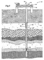
- a subsurface safety valve in use with an offshore oil and gas production platform is schematically illustrated and generally designated 10.
- a semi-submersible platform 12 is centered over a submerged oil and gas formation 14 located below sea floor 16.
- Wellhead 18 is located on deck 20 of platform 12.
- Well 22 extends through the sea 24 and penetrates the various earth strata including formation 14 to form wellbore 26.
- casing 28 Disposed within wellbore 26 is casing 28.
- casing 28 and extending from wellhead 18 is production tubing 30.
- a pair of seal assemblies 32, 34 provide a seal between tubing 30 and casing 28 to prevent the flow of production fluids therebetween.
- formation fluids enter wellbore 26 through perforations 36 of casing 28 and travel into tubing 30 through sand control device 38 to wellhead 18.
- Subsurface safety valve 40 is located within the production tubing 30 and seals the wellhead 18 from formation 14 in the event of abnormal conditions.
- Subsurface safety valve 40 includes a flapper valve closure plate that, during production from formation 14, is maintained in the valve open position by hydraulic control pressure received from a surface control system 42 through a control conduit 44.
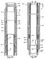
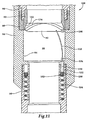
- Safety valve 50 is connected directly in series with production tubing 30. Hydraulic control pressure is conducted in communication with a longitudinal bore 52 formed in the sidewall of the top connector sub 54. Pressurized hydraulic fluid is delivered through the longitudinal bore 52 into an annular chamber 56 defined by a counterbore 58 which is in communication with an annular undercut 60 formed in the sidewall of the top connector sub 54.
- An inner housing mandrel 62 is slidably coupled and sealed to the top connector sub 54 by a slip union 64 and seal 66, with the undercut 60 defining an annulus between inner mandrel 62 and the sidewall of top connector sub 54.
- a piston 68 is received in slidable, sealed engagement against the internal bore of inner mandrel 62.
- the undercut annulus 60 opens into a piston chamber 70 in the annulus between the internal bore of a connector sub 72 and the external surface of piston 68.
- the external radius of an upper sidewall piston section 74 is machined and reduced to define a radial clearance between piston 68 and connector sub 72.
- An annular sloping surface 76 of piston 68 is acted against by the pressurized hydraulic fluid delivered through control conduit 44.
- piston 68 is fully extended with the piston shoulder 78 engaging the top annular face 80 of an operator tube 82 such that a return spring 84 is fully compressed and valve 50 is in the valve open position.
- a flapper plate 86 is pivotally mounted onto a hinge sub 88 which is threadably connected to the lower end of spring housing 90.
- a valve seat 92 is confined within hinge sub 88.
- the lower end of safety valve 50 is connected to production tubing 30 by a bottom sub connector 94.
- the bottom sub connector 94 has a counterbore 96 which defines a flapper valve chamber 98.
- the bottom sub connector 94 forms a part of the flapper valve housing enclosure.
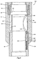
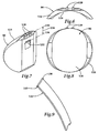
- Flapper plate 86 pivots on hinge 100 and is biased about 90° to the valve closed position as shown in figures 3A-3B by flapper valve closure assembly 102 housed partially within hole 104 in tubing 30. In the valve open position as shown in figures 2A-2B, the bias force of flapper valve closure assembly 102 is overcome and flapper plate 86 is retained in the valve open position by operator tube 82 to permit formation fluid flow up through tubing 30.
- Flapper valve assembly 110 includes a flapper closure plate 86 that is bias to the closed position by flapper valve closure assembly 102.
- the sealing surfaces of flapper closure plate 86 and valve seat 92 have mating spherical segments which are matched in curvature to provide a metal-to-metal seal. It has been found that the use of metal-to-metal contact between nesting spherical segments provides a continuous, positive seal that is maintained completely around the spherical segment interface.
- Flapper valve closure assembly 102 includes one or more compression springs 116, only one of which is shown, that are disposed within longitudinal hole 104. Flapper valve closure assembly 102 also includes a piston 118 that has shoulder 120 which contacts compression spring 116 within longitudinal hole 104. A connection member 122 is coupled to piston 118 on the end opposite spring 116 with coupling 124. In the illustrated embodiment, connection member 122 is rotatably coupled to piston 118. On the end opposite coupling 124, connection member 122 engages flapper closure plate 86 as will be more fully discussed below.
- connection member 122 contacts counterbore 96 of flapper valve chamber 98.
- connection member 122 acts like a leaf spring and further biases flapper closure plate 86 toward the closed position. This result is achieved due to the arcuate shape of connection member 122 which assures that a moment will be applied about hinge 100 even when flapper closure plate 86 is in the fully opened position.
- Flapper closure plate 86 has a arcuate shaped face 126 which receives operator tube 82 when flapper closure plate 86 is operated from the closed position to the open position. Flapper closure plate 86 also includes a pair of hinge members 128 through which a pin is inserted along axis 130 to couple hinge members 128 of flapper closure plate 86 with hinge 100. Flapper closure plate 86 includes a notch 132. Notch 132 has an axis of rotation 134 located therein. The distance 136 between axis 130 and axis 134 defines the length of the moment arm used to bias flapper closure plate 86 from the open position to the closed position. Distance 136 may be adjusted as necessary depending upon the size and weight of flapper closure plate 86.
- connection member 122 is inserted into notch 132 of flapper closure plate 86.
- Connection member 122 includes a pair of pins 138, 140 that are received within notch 132 and assure that connection member 122 does not become separated from flapper closure plate 86 during operation.
- connection member 132 has an arcuate shape which allows connection member 122 to act as a leaf spring and bias flapper closure plate 86 toward the closed position when flapper closure plate 86 is in its fully open position.
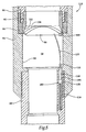
- Flapper valve assembly 150 includes a flapper closure plate 86 that is bias to the closed position by flapper valve closure assembly 102.
- Flapper valve closure assembly 102 includes a compression spring 154 that is disposed within annular hole 152.
- Flapper valve closure assembly 102 also includes a piston 156 that has sleeve 158 which contacts compression spring 154 within annular hole 152.
- a connection member 122 is coupled to piston 156 on the end opposite spring 154 with coupling 124. In the illustrated embodiment, connection member 122 is rotatably coupled to piston 156. On the end opposite coupling 124, connection member 122 engages flapper closure plate 86 as described above.
- connection member 122 contacts counterbore 96 of flapper valve chamber 98.
- connection member 122 acts like a leaf spring and further biases flapper closure plate 86 toward the closed position. This result is achieved due to the arcuate shape of connection member 122 which assures that a moment will be applied about hinge 100 even when flapper closure plate 86 is in the fully opened position.
Landscapes
- Engineering & Computer Science (AREA)
- Geology (AREA)
- Life Sciences & Earth Sciences (AREA)
- Mining & Mineral Resources (AREA)
- Environmental & Geological Engineering (AREA)
- Fluid Mechanics (AREA)
- Physics & Mathematics (AREA)
- General Life Sciences & Earth Sciences (AREA)
- Geochemistry & Mineralogy (AREA)
- General Engineering & Computer Science (AREA)
- Mechanical Engineering (AREA)
- Lift Valve (AREA)
- Closures For Containers (AREA)
Claims (10)
- Ein Klappenventil (110), umfassend ein rohrförmiges Ventilgehäuse (94) mit einem Scharnier (100) und einem Loch (104); einen Ventilsitz (92), montiert innerhalb des Gehäuses (94), mit einer Ventilsitz-Abdichtungsfläche, wobei der Ventilsitz (92) einen Fließdurchgang durch denselben hindurch definiert; eine Klappenschließplatte (86), drehbar mit dem Scharnier (100) gekoppelt und zwischen einer geöffneten Ventilposition, in welcher die Klappenschließplatte (86) von dem Ventilsitz (92) entfernt wird, und einer geschlossenen Ventilposition, in welcher eine Abdichtungsfläche der Klappenschließplatte (86) abdichtend in die Ventilsitz-Abdichtungsfläche eingreift und einen Durchfluß durch den Fließdurchgang verhindert, drehbar; und eine Klappenschließeinheit (102), welche die Klappenschließplatte (86) in Richtung der geschlossenen Position vorspannt, wobei die Klappenschließeinheit (102) eine innerhalb des Lochs (104) montierte Feder (116) und ein die Feder (116) betrieblich mit der Klappenschließplatte (86) koppelndes Verbindungsteil (122) umfasst, so dass die Feder (116) zusammen gedrückt wird, wenn die Klappenschließplatte (86) in Richtung der geöffneten Position bewegt wird, und das Verbindungsteil (122) dazu zwingt, die Klappenschließplatte (86) in Richtung der geschlossenen Position zu drücken, dadurch gekennzeichnet, dass das Verbindungsteil (122) eine gebogene Form aufweist, so dass das Verbindungsteil (122) ein Moment auf die Klappenschließplatte (86) ausübt, wenn die Klappenschließplatte (86) sich in der geöffneten Position befindet.
- Eine Klappenventileinheit (110) nach Anspruch 1, bei welcher das Verbindungsteil (122) drehbar in eine Einkerbung (132) in der Klappenschließplatte (86) empfangen wird.
- Eine Klappenventileinheit (110) nach Anspruch 1 oder 2, bei welcher die Klappenventilschließeinheit (102) weiter ein Kolbenteil (118) umfasst, welches zumindest zum Teil innerhalb des Lochs (104) positioniert ist, und das Kolbenteil (118) die Feder (116) mit dem Verbindungsteil (122) gekoppelt.
- Eine Klappenventileinheit (110) nach Anspruch 1, 2, oder 3, bei welcher das Verbindungsteil (122) drehbar mit dem Kolbenteil (118) gekoppelt ist.
- Ein Untergrundsicherheitsventil (50), welches für das Platzieren in einer Bohrlochrohranordnung adaptiert ist, für das Kontrollieren des Durchflusses durch dieselben, umfassend: ein Ventilgehäuse (94) mit einer Bohrung, ein Scharnier (100), und ein längliches Loch (104); eine innerhalb der Bohrung montierte und um das Scharnier (100) herum drehbare Klappenschließplatte (86), wobei die Klappenschließplatte (86) zwischen einer geöffneten Position und einer geschlossenen Position bewegbar ist, und die Klappenschließplatte (86) eine Abdichtungsfläche auf einer Seite, und eine Einkerbung (132) auf der gegenüber liegenden Seite umfasst; ein vom Betreiber bewegbarer, innerhalb des Bohrlochs positionierter, für das Kontrollieren der Bewegung der Klappenschließplatte (86) von der geschlossenen Position auf die geöffnete Position; eine Klappenschließeinheit (102), welche die Klappenschließeinheit (86) in Richtung der geschlossenen Position vorspannt, wobei die Klappenschließeinheit (102) eine innerhalb des länglichen Lochs (104) montierte Feder (116) und ein Verbindungsteil (122) umfasst, welches betrieblich mit der Feder (116) gekoppelt ist und in die Einkerbung (132) eingreift, so dass die Feder (116) zusammen gedrückt wird, wenn die Klappenschließplatte (86) in Richtung der geöffneten Position bewegt wird, und das Verbindungsteil (122) dazu zwingt, die Klappenschließplatte (86) in Richtung der geschlossenen Position zu drücken, und ein innerhalb des Ventilgehäuses (94) positionierter Ventilsitz (92), wobei der Ventilsitz (92) eine Abdichtungsfläche umfasst, und die Abdichtungsfläche der Klappenschließplatte (86) in der geschlossenen Position abdichtend in die Abdichtungsfläche des Ventilsitzes (92) eingreift, dadurch gekennzeichnet, dass das Verbindungsteil (122) eine gebogene Form aufweist, so dass das Verbindungsteil (122) ein Moment auf die Klappenschließplatte (86) ausübt, wenn die Klappenschließplatte (86) sich in der geöffneten Position befindet.
- Ein Untergrundsicherheitsventil (50) nach Anspruch 5, bei welchem das Verbindungsteil (122) drehbar innerhalb der Einkerbung (132) der Klappenschließplatte (86) empfangen wird.
- Ein Untergrundsicherheitsventil (50) nach Anspruch 5 oder 6, bei welchem die Klappenventilschließeinheit (102) weiter ein Kolbenteil (118) umfasst, welches zumindest zum Teil innerhalb des Lochs (104) positioniert ist, wobei das Kolbenteil (118) die Feder (116) mit dem Verbindungsteil (122) koppelt.
- Eine Klappenventileinheit (110) nach Anspruch 1, bei welcher das genannte Loch (104) länglich ist, und bei welcher die genannte Ventilsitzfläche (144) der Klappenschließplatte (86) auf einer Seite der genannten Klappenschließplatte, und eine Einkerbung (132) auf der gegenüber liegenden Seite der genannten Klappenschließplatte (86) umfasst und von dem Scharnier (100) beabstandet positioniert ist; und die Klappenschließeinheit (102) umfasst weiter einen Kolben (118), welcher zumindest zum Teil innerhalb des länglichen Lochs (104) positioniert ist und betrieblich mit der Feder (116) gekoppelt ist, wobei das genannte Verbindungsteil (122) drehbar mit der Feder (116) gekoppelt ist und drehbar in die Einkerbung (132) eingreift.
- Eine Klappenventileinheit (110) nach Anspruch 8, bei welcher das Verbindungsteil (122) weiter ein Teil mit einer gebogenen Form umfasst, so dass das Verbindungsteil (122) ein Moment auf die Klappenschließplatte (86) ausübt, wenn die Klappenschließplatte (86) sich in der geöffneten Position befindet.
- Eine Klappenschließeinheit (110) nach Anspruch 8 oder 9, bei welcher die Klappenschließplatte (86) zwischen der geschlossenen Position und der geöffneten Position ungefähr 90° zurücklegt.
Applications Claiming Priority (2)
| Application Number | Priority Date | Filing Date | Title |
|---|---|---|---|
| US09/351,397 US6227299B1 (en) | 1999-07-13 | 1999-07-13 | Flapper valve with biasing flapper closure assembly |
| US351397 | 1999-07-13 |
Publications (3)
| Publication Number | Publication Date |
|---|---|
| EP1069279A2 EP1069279A2 (de) | 2001-01-17 |
| EP1069279A3 EP1069279A3 (de) | 2001-01-24 |
| EP1069279B1 true EP1069279B1 (de) | 2005-05-18 |
Family
ID=23380749
Family Applications (1)
| Application Number | Title | Priority Date | Filing Date |
|---|---|---|---|
| EP20000305885 Expired - Lifetime EP1069279B1 (de) | 1999-07-13 | 2000-07-12 | Klappenventil mit Schliessunterstützung |
Country Status (3)
| Country | Link |
|---|---|
| US (1) | US6227299B1 (de) |
| EP (1) | EP1069279B1 (de) |
| SG (1) | SG85199A1 (de) |
Cited By (3)
| Publication number | Priority date | Publication date | Assignee | Title |
|---|---|---|---|---|
| CN109519143A (zh) * | 2019-01-15 | 2019-03-26 | 陈超 | 四闸板连续油管封井器 |
| CN109519144A (zh) * | 2019-01-15 | 2019-03-26 | 陈超 | 四闸板连续油管封井器的使用方法 |
| AU2020203973B2 (en) * | 2013-01-18 | 2021-11-25 | Weatherford Technology Holdings, Llc | Bidirectional downhole isolation valve |
Families Citing this family (66)
| Publication number | Priority date | Publication date | Assignee | Title |
|---|---|---|---|---|
| GB2368079B (en) * | 2000-10-18 | 2005-07-27 | Renovus Ltd | Well control |
| US6497278B1 (en) * | 2001-03-19 | 2002-12-24 | Varco I/P | Circulation control device |
| US6644411B2 (en) * | 2001-04-18 | 2003-11-11 | Kvaerner Oilfield Products, Inc. | Tubing hanger with flapper valve |
| US6585000B2 (en) | 2001-09-04 | 2003-07-01 | Lydell Radford | Pressure relief valve |
| US6957703B2 (en) * | 2001-11-30 | 2005-10-25 | Baker Hughes Incorporated | Closure mechanism with integrated actuator for subsurface valves |
| US6877564B2 (en) | 2002-09-30 | 2005-04-12 | Baker Hughes Incorporated | Flapper closure mechanism |
| US7255173B2 (en) | 2002-11-05 | 2007-08-14 | Weatherford/Lamb, Inc. | Instrumentation for a downhole deployment valve |
| RU2250354C2 (ru) * | 2003-05-05 | 2005-04-20 | Открытое акционерное общество "Научно-производственное объединение "Бурение" | Стационарный проходной клапан-отсекатель |
| US7021386B2 (en) | 2003-08-18 | 2006-04-04 | Halliburton Energy Services, Inc. | Safety valve having extension spring closure mechanism |
| US7287596B2 (en) * | 2004-12-09 | 2007-10-30 | Frazier W Lynn | Method and apparatus for stimulating hydrocarbon wells |
| US7798229B2 (en) * | 2005-01-24 | 2010-09-21 | Halliburton Energy Services, Inc. | Dual flapper safety valve |
| RU2311526C2 (ru) * | 2005-09-08 | 2007-11-27 | Открытое акционерное общество "Научно-производственное объединение "Бурение" | Клапан-отсекатель |
| US8453746B2 (en) * | 2006-04-20 | 2013-06-04 | Halliburton Energy Services, Inc. | Well tools with actuators utilizing swellable materials |
| US7708068B2 (en) * | 2006-04-20 | 2010-05-04 | Halliburton Energy Services, Inc. | Gravel packing screen with inflow control device and bypass |
| US8342247B2 (en) * | 2006-04-21 | 2013-01-01 | Halliburton Energy Services, Inc. | Safety valve having mono spring closure mechanism |
| GB0608334D0 (en) * | 2006-04-27 | 2006-06-07 | Petrowell Ltd | Apparatus |
| RU2311578C1 (ru) * | 2006-06-07 | 2007-11-27 | Общество с ограниченной ответственностью Финансово-промышленная компания "Космос-Нефть-Газ" | Клапан-отсекатель для газовой скважины и способ его эксплуатации |
| US20080041582A1 (en) * | 2006-08-21 | 2008-02-21 | Geirmund Saetre | Apparatus for controlling the inflow of production fluids from a subterranean well |
| US20080041580A1 (en) * | 2006-08-21 | 2008-02-21 | Rune Freyer | Autonomous inflow restrictors for use in a subterranean well |
| US20080041588A1 (en) * | 2006-08-21 | 2008-02-21 | Richards William M | Inflow Control Device with Fluid Loss and Gas Production Controls |
| US7762323B2 (en) * | 2006-09-25 | 2010-07-27 | W. Lynn Frazier | Composite cement retainer |
| US7644767B2 (en) * | 2007-01-02 | 2010-01-12 | Halliburton Energy Services, Inc. | Safety valve with flapper/flow tube friction reducer |
| AU2007346700B2 (en) * | 2007-02-06 | 2013-10-31 | Halliburton Energy Services, Inc. | Swellable packer with enhanced sealing capability |
| EP2535504B1 (de) * | 2007-04-04 | 2015-04-22 | Weatherford Technology Holdings, LLC | Bohrloch-Einsetzventile |
| US20080283238A1 (en) * | 2007-05-16 | 2008-11-20 | William Mark Richards | Apparatus for autonomously controlling the inflow of production fluids from a subterranean well |
| US20100163241A1 (en) * | 2007-07-19 | 2010-07-01 | Dudley Iles Klatt | Modular saddle flapper valve |
| US7832486B2 (en) * | 2007-08-15 | 2010-11-16 | Schlumberger Technology Corporation | Flapper gas lift valve |
| CA2639341C (en) * | 2007-09-07 | 2013-12-31 | W. Lynn Frazier | Downhole sliding sleeve combination tool |
| US8474535B2 (en) * | 2007-12-18 | 2013-07-02 | Halliburton Energy Services, Inc. | Well screen inflow control device with check valve flow controls |
| US7708066B2 (en) * | 2007-12-21 | 2010-05-04 | Frazier W Lynn | Full bore valve for downhole use |
| RU2399821C1 (ru) * | 2009-03-26 | 2010-09-20 | Общество с ограниченной ответственностью Финансово-промышленная компания "Космос-Нефть-Газ" | Клапан-отсекатель для газовой скважины |
| US8424842B2 (en) * | 2009-04-15 | 2013-04-23 | Baker Hughes Incorporated | Rotationally-actuated flapper valve and method |
| US20110155392A1 (en) * | 2009-12-30 | 2011-06-30 | Frazier W Lynn | Hydrostatic Flapper Stimulation Valve and Method |
| US8739881B2 (en) * | 2009-12-30 | 2014-06-03 | W. Lynn Frazier | Hydrostatic flapper stimulation valve and method |
| US8733448B2 (en) * | 2010-03-25 | 2014-05-27 | Halliburton Energy Services, Inc. | Electrically operated isolation valve |
| CN101812982A (zh) * | 2010-04-13 | 2010-08-25 | 中国石油大学(北京) | 油气井生产用井底过管柱开关阀装置 |
| US10030644B2 (en) | 2010-04-23 | 2018-07-24 | Lawrence Osborne | Flow router with retrievable valve assembly |
| EP2576958B1 (de) * | 2010-05-24 | 2018-09-12 | Blackhawk Specialty Tools, LLC | Flussvorrichtung zum füllen grosser bohrlöcher |
| US8776889B2 (en) * | 2010-07-14 | 2014-07-15 | Weatherford/Lamb, Inc. | Irregularly shaped flapper closure and sealing surfaces |
| US8439118B2 (en) * | 2010-07-28 | 2013-05-14 | Baker Hughes Incorporated | Pressure vortex device to allow flapper closure in high velocity fluid applications |
| US8708051B2 (en) | 2010-07-29 | 2014-04-29 | Weatherford/Lamb, Inc. | Isolation valve with debris control and flow tube protection |
| CN102418495B (zh) * | 2010-09-28 | 2014-11-05 | 中国石油化工集团公司 | 一种欠平衡井下套管阀阀板及其加工方法 |
| RU2445445C1 (ru) * | 2010-10-18 | 2012-03-20 | Дмитрий Иванович Александров | Устройство запорное автономное |
| NO333665B1 (no) * | 2011-01-25 | 2013-08-05 | Ts Innovation As | Tilbakeslagsventil |
| JP5707484B2 (ja) * | 2011-03-11 | 2015-04-30 | イイダ産業株式会社 | 発泡性充填具 |
| US8757274B2 (en) | 2011-07-01 | 2014-06-24 | Halliburton Energy Services, Inc. | Well tool actuator and isolation valve for use in drilling operations |
| US8479826B2 (en) | 2011-10-20 | 2013-07-09 | Halliburton Energy Services, Inc. | Protection of a safety valve in a subterranean well |
| WO2013089730A1 (en) * | 2011-12-15 | 2013-06-20 | Halliburton Energy Services, Inc. | Dual closure system for well system |
| US9157299B2 (en) | 2011-12-15 | 2015-10-13 | Halliburton Energy Services, Inc. | Integrated opening subsystem for well closure system |
| WO2013089753A1 (en) | 2011-12-15 | 2013-06-20 | Halliburton Energy Services, Inc. | Subsurface safety valve deployable via electric submersible pump |
| US9206913B2 (en) | 2013-03-05 | 2015-12-08 | Hamilton Sundstrand Corporation | Check valve having petals with lift generating elements |
| WO2015020634A1 (en) * | 2013-08-06 | 2015-02-12 | Halliburton Energy Services, Inc. | Wave spring flapper closure mechanism |
| CN104074493A (zh) * | 2014-07-09 | 2014-10-01 | 中国海洋石油总公司 | 热采防污染井下开关 |
| JP6324870B2 (ja) * | 2014-10-08 | 2018-05-16 | 東京エレクトロン株式会社 | ガス供給機構及び半導体製造装置 |
| US10662740B2 (en) | 2016-04-14 | 2020-05-26 | Downing Wellhead Equipment, Llc | Valve apparatus |
| CN107130939B (zh) * | 2017-07-17 | 2023-04-18 | 东营市瑞丰石油技术发展有限责任公司 | 压力开启式防漏失阀及开关装置 |
| US10689938B2 (en) | 2017-12-14 | 2020-06-23 | Downing Wellhead Equipment, Llc | Subterranean formation fracking and well workover |
| US10941869B2 (en) * | 2018-04-25 | 2021-03-09 | Joshua Terry Prather | Dual lock flow gate |
| US10677018B2 (en) * | 2018-06-22 | 2020-06-09 | Baker Hughes, A Ge Company, Llc | Actuator mechanism for a valve system |
| GB2596765B (en) * | 2019-05-29 | 2022-12-14 | Halliburton Energy Services Inc | Flapper valve with beam spring |
| WO2020242465A1 (en) * | 2019-05-29 | 2020-12-03 | Halliburton Energy Services, Inc. | Variable torque flapper valve |
| CA3171459C (en) * | 2020-03-12 | 2023-09-19 | Michael Herrera | Apparatus and method for activation of flapper check valve |
| US11697977B2 (en) | 2021-01-14 | 2023-07-11 | Saudi Arabian Oil Company | Isolation valve for use in a wellbore |
| US11391120B1 (en) * | 2021-04-26 | 2022-07-19 | Halliburton Energy Services, Inc. | Robustness of flapper valve open/close |
| CA3210252A1 (en) * | 2021-04-26 | 2022-11-03 | Halliburton Energy Services, Inc. | Improving robustness of flapper valve open/close |
| CN117211726B (zh) * | 2023-08-04 | 2025-10-28 | 四机赛瓦石油钻采设备有限公司 | 一种机械式可重复开关气密封阀、专用工具及使用方法 |
Family Cites Families (8)
| Publication number | Priority date | Publication date | Assignee | Title |
|---|---|---|---|---|
| US3482603A (en) * | 1967-08-03 | 1969-12-09 | Dale E Outcalt | Shut-off valve for flow conduits |
| US3980135A (en) * | 1971-08-18 | 1976-09-14 | Schlumberger Technology Corporation | Self-contained, retrievable valving assembly |
| US4706933A (en) * | 1985-09-27 | 1987-11-17 | Sukup Richard A | Oil and gas well safety valve |
| US5145005A (en) | 1991-04-26 | 1992-09-08 | Otis Engineering Corporation | Casing shut-in valve system |
| US5201371A (en) * | 1991-05-03 | 1993-04-13 | Allen Charles W | Back pressure flapper valve |
| US5159981A (en) | 1991-06-20 | 1992-11-03 | Otis Engineering Corporation | Flapper valve |
| US6079497A (en) * | 1997-06-03 | 2000-06-27 | Camco International Inc. | Pressure equalizing safety valve for subterranean wells |
| US6050294A (en) * | 1999-03-17 | 2000-04-18 | Val-Matic Valve And Manufacturing Corp. | Spring return check valve |
-
1999
- 1999-07-13 US US09/351,397 patent/US6227299B1/en not_active Expired - Lifetime
-
2000
- 2000-07-11 SG SG200003881A patent/SG85199A1/en unknown
- 2000-07-12 EP EP20000305885 patent/EP1069279B1/de not_active Expired - Lifetime
Cited By (5)
| Publication number | Priority date | Publication date | Assignee | Title |
|---|---|---|---|---|
| AU2020203973B2 (en) * | 2013-01-18 | 2021-11-25 | Weatherford Technology Holdings, Llc | Bidirectional downhole isolation valve |
| CN109519143A (zh) * | 2019-01-15 | 2019-03-26 | 陈超 | 四闸板连续油管封井器 |
| CN109519144A (zh) * | 2019-01-15 | 2019-03-26 | 陈超 | 四闸板连续油管封井器的使用方法 |
| CN109519144B (zh) * | 2019-01-15 | 2020-11-20 | 陈超 | 四闸板连续油管封井器的使用方法 |
| CN109519143B (zh) * | 2019-01-15 | 2021-06-04 | 大庆丹枫石油技术开发有限公司 | 四闸板连续油管封井器 |
Also Published As
| Publication number | Publication date |
|---|---|
| EP1069279A3 (de) | 2001-01-24 |
| SG85199A1 (en) | 2001-12-19 |
| EP1069279A2 (de) | 2001-01-17 |
| US6227299B1 (en) | 2001-05-08 |
Similar Documents
| Publication | Publication Date | Title |
|---|---|---|
| EP1069279B1 (de) | Klappenventil mit Schliessunterstützung | |
| US6851477B2 (en) | Curved flapper with angle variant seat for a subsurface safety valve | |
| US4252197A (en) | Piston actuated well safety valve | |
| US5310005A (en) | Flapper valve assembly with floating hinge | |
| US5137089A (en) | Streamlined flapper valve | |
| US6289926B1 (en) | Flapper valve assembly with seat having load bearing shoulder | |
| US6263910B1 (en) | Valve with secondary load bearing surface | |
| US4161219A (en) | Piston actuated well safety valve | |
| US4291722A (en) | Drill string safety and kill valve | |
| US3868995A (en) | Sub-surface safety valve | |
| US6296061B1 (en) | Pilot-operated pressure-equalizing mechanism for subsurface valve | |
| US4444266A (en) | Deep set piston actuated well safety valve | |
| US8151887B2 (en) | Lubricator valve | |
| US7543651B2 (en) | Non-elastomer cement through tubing retrievable safety valve | |
| GB2256665A (en) | Flapper valve assemblies | |
| CA2286889C (en) | Pressure-balanced rod piston control system for a subsurface safety val ve | |
| GB2090889A (en) | Safety valve system with retrievable equalizing feature | |
| US7178599B2 (en) | Subsurface safety valve | |
| US20200056714A1 (en) | Deep set production tubing pressure insensitive wireline retrievable safety valve | |
| CA2496331C (en) | Seal assembly for a safety valve | |
| US4716968A (en) | Double seated well valve | |
| WO2020139370A1 (en) | Combined chemical/balance line | |
| EP0985798A2 (de) | Vorrichtung zum Öffnen und Schliessen eines Klappenventiles | |
| GB2616431A (en) | Apparatus | |
| WO1991006743A1 (en) | Bottom hole blowout preventer |
Legal Events
| Date | Code | Title | Description |
|---|---|---|---|
| PUAI | Public reference made under article 153(3) epc to a published international application that has entered the european phase |
Free format text: ORIGINAL CODE: 0009012 |
|
| PUAL | Search report despatched |
Free format text: ORIGINAL CODE: 0009013 |
|
| AK | Designated contracting states |
Kind code of ref document: A2 Designated state(s): FR GB |
|
| AX | Request for extension of the european patent |
Free format text: AL;LT;LV;MK;RO;SI |
|
| AK | Designated contracting states |
Kind code of ref document: A3 Designated state(s): AT BE CH CY DE DK ES FI FR GB GR IE IT LI LU MC NL PT SE |
|
| AX | Request for extension of the european patent |
Free format text: AL;LT;LV;MK;RO;SI |
|
| 17P | Request for examination filed |
Effective date: 20010713 |
|
| AKX | Designation fees paid |
Free format text: FR GB |
|
| REG | Reference to a national code |
Ref country code: DE Ref legal event code: 8566 |
|
| 17Q | First examination report despatched |
Effective date: 20040210 |
|
| GRAP | Despatch of communication of intention to grant a patent |
Free format text: ORIGINAL CODE: EPIDOSNIGR1 |
|
| GRAA | (expected) grant |
Free format text: ORIGINAL CODE: 0009210 |
|
| GRAS | Grant fee paid |
Free format text: ORIGINAL CODE: EPIDOSNIGR3 |
|
| AK | Designated contracting states |
Kind code of ref document: B1 Designated state(s): FR GB |
|
| REG | Reference to a national code |
Ref country code: GB Ref legal event code: FG4D |
|
| PGFP | Annual fee paid to national office [announced via postgrant information from national office to epo] |
Ref country code: GB Payment date: 20050706 Year of fee payment: 6 |
|
| PLBE | No opposition filed within time limit |
Free format text: ORIGINAL CODE: 0009261 |
|
| STAA | Information on the status of an ep patent application or granted ep patent |
Free format text: STATUS: NO OPPOSITION FILED WITHIN TIME LIMIT |
|
| 26N | No opposition filed |
Effective date: 20060221 |
|
| PG25 | Lapsed in a contracting state [announced via postgrant information from national office to epo] |
Ref country code: GB Free format text: LAPSE BECAUSE OF NON-PAYMENT OF DUE FEES Effective date: 20060712 |
|
| EN | Fr: translation not filed | ||
| GBPC | Gb: european patent ceased through non-payment of renewal fee |
Effective date: 20060712 |
|
| PG25 | Lapsed in a contracting state [announced via postgrant information from national office to epo] |
Ref country code: FR Free format text: LAPSE BECAUSE OF NON-PAYMENT OF DUE FEES Effective date: 20050731 |
|
| PG25 | Lapsed in a contracting state [announced via postgrant information from national office to epo] |
Ref country code: FR Free format text: LAPSE BECAUSE OF NON-PAYMENT OF DUE FEES Effective date: 20050518 |