EP1069267B1 - Latch arrangement - Google Patents
Latch arrangement Download PDFInfo
- Publication number
- EP1069267B1 EP1069267B1 EP20000305756 EP00305756A EP1069267B1 EP 1069267 B1 EP1069267 B1 EP 1069267B1 EP 20000305756 EP20000305756 EP 20000305756 EP 00305756 A EP00305756 A EP 00305756A EP 1069267 B1 EP1069267 B1 EP 1069267B1
- Authority
- EP
- European Patent Office
- Prior art keywords
- transmission path
- latch
- latch arrangement
- door
- break
- Prior art date
- Legal status (The legal status is an assumption and is not a legal conclusion. Google has not performed a legal analysis and makes no representation as to the accuracy of the status listed.)
- Expired - Lifetime
Links
- 230000005540 biological transmission Effects 0.000 claims description 48
- 230000002159 abnormal effect Effects 0.000 claims 9
- 208000012661 Dyskinesia Diseases 0.000 claims 1
- 210000000078 claw Anatomy 0.000 description 3
- 208000027418 Wounds and injury Diseases 0.000 description 1
- 230000000903 blocking effect Effects 0.000 description 1
- 230000006835 compression Effects 0.000 description 1
- 238000007906 compression Methods 0.000 description 1
- 230000006378 damage Effects 0.000 description 1
- 230000000694 effects Effects 0.000 description 1
- 208000014674 injury Diseases 0.000 description 1
- 230000000717 retained effect Effects 0.000 description 1
Images

Classifications
-
- E—FIXED CONSTRUCTIONS
- E05—LOCKS; KEYS; WINDOW OR DOOR FITTINGS; SAFES
- E05B—LOCKS; ACCESSORIES THEREFOR; HANDCUFFS
- E05B77/00—Vehicle locks characterised by special functions or purposes
- E05B77/02—Vehicle locks characterised by special functions or purposes for accident situations
- E05B77/12—Automatic locking or unlocking at the moment of collision
Definitions
- the present invention relates to latch arrangements and in particular latch arrangements for releasably securing vehicle doors such as car doors in a closed position.
- US4995654 shows a latch arrangement which is normally lockable by operation of an internal sill button or an external key barrel arrangement.
- the lock mechanism includes various levers, one of which has an extension arm situated on the inside of the external door skin. Deformation inwardly of the door skin causes the extension arm to move the latch mechanism to its normal locked position.
- latch arrangement as defined in claim 1.
- latch arrangement as defined in claim 9.
- a latch arrangement 10 for use with a car side door the latch arrangement 10 including a latch mechanism 12 (only part of which is shown), a transmission path 14 and a release means in the form of an inside door handle 16 (shown schematically).
- the door would be hinged at a front edge, though in further embodiments this need not be the case.
- the latch mechanism 12 includes a housing 18 on which is pivoted latch mechanism inside release lever 20.
- the housing 18 further includes a latch bolt (not shown) for engagement with a striker pin secured to fixed structure of the car such as a B post or a C post.
- the latch bolt is retained in a close position by a pawl (not shown), thus allowing the latch arrangement to secure the door in a closed position.
- the pawl is operably connected to the latch mechanism inside release lever 20 via transmission elements (not shown) of the transmission path 14.
- a rod 22 is pivotally connected at end 22A via pivot 24 to inside door handle 16.
- the rod 22 is bent at 90° and includes first abutment 26, second abutment 28 and third abutment 30 all being provided on the bent portion of the rod 22. End 22B passes through a hole in latch mechanism inside release lever 20.
- a resilient means in the form of a spring 32 is mounted on end 22B and abuts third abutment 30 and the edge of the hole in the latch mechanism inside release lever 20.
- the latch mechanism 12 can be locked and unlocked by actuation of lock lever 34.
- lock lever 34 When lock lever 34 is in position U, as shown in figure 1, the latch mechanism 12 is unlocked and when lock lever 34 is in position L, as shown in figure 1, the latch mechanism is locked.
- Locking can be effected by lock lever 34 providing a break in the transmission path whereby operation of inside door handle 16 is possible but has no effect or by lock lever 34 providing a block in the trammission path whereby operation of inside door handle 16 is prevented thus similarly leaving the door in a locked condition.
- transmission elements of the transmission path include rod 22, inside release lever 20, the pawl and the blocking or breaking element (not shown) connected to lock lever 34. It is the various elements of the transmission path which connect the inside door handle ultimately to the latch bolt.
- the latch assembly 10 is contained within a door 50, having a door outer skin 51. Connected to an inner portion of the door skin 51 is a defamation abutment 52.
- deformation 52 is solely provided for transmitting an impact on the door skin 51 to the transmission path.
- the deformation abutment can form part of further components, for example, window regulator rails.
- any subsequent deformation of the latch arrangement in particular deformation of the rod 22 which puts the rod into tension and thus potentially causes rotation of the latch mechanism inside release lever 20 will not unlatch the door since the initial deformation put the door into a locked condition. It can be seen that the initial deformation which puts the latch mechanism into a locked condition is allowed for by resilient deformation of spring 32.
- a contact abutment 52 is located proximal end 22b of rod 22, ie proximal the latch mechanism 12.
- a second embodiment of a latch arrangement which includes a latch mechanism 112, a transmission path 114, a housing 118, a latch mechanism inside release lever 120, a rod 122 and a spring 132.
- the latch mechanism further includes a release lever 140 operably situated between the latch mechanism inside release lever 120 and the pawl (not shown).
- Release lever 140 is pivotally mounted about pivot 142 and includes a tab 144.
- the latch arrangement 110 is mounted within a door 146 which defines a door plane D.P. Normal operation of the latch arrangement causes rod 122 to move in the direction of arrow C within a movement plane M.P which is generally parallel to the door plane D.P.
- the invention is not limited to use with a transmission path connecting a latch bolt with an inside handle of a door, in particular the invention could be used in conjunction with an outside door handle of a vehicle.
- the latch arrangement includes a first transmission path between the latch bolt and an inside door handle and a second transmission path between the latch bolt and outside door handle
- initial deformation of the latch arrangement could be arranged to cause a first break or block in the in the first transmission path and a second break or block in the second transmission path.
- the break or block could be provided in the common part of the transmission path thus only requiring one block or break to secure the door from opening.
- a car door can be locked whereby operation of an outside door handle does not open the latch, or whereby operation of an inside door handle does not operate the latch (also known as a child safety condition) or the door can be locked such that operation of either the outside or inside door handle does not operate the latch (known as super locked or dead locked condition) and the present invention is applicable to all these types of locking.
- locking can be effected by providing a break between a door handle and the claw such that the door handle 'free wheels' without opening the latch, or locking can be provided by creating a block between the door handle and claw such that the block prevents movement of the door handle and the present invention is applicable to 'break' or ⁇ block' type locking.
- the lock lever 34 can either provide such a break or block directly or can act on further levers or the like which themselves provide the break or block.
Landscapes
- Lock And Its Accessories (AREA)
Description
- The present invention relates to latch arrangements and in particular latch arrangements for releasably securing vehicle doors such as car doors in a closed position.
- When known latch arrangements are used on car doors, and the car has subsequently been involved in a road accident where the door has been deformed, the very act of deforming the door has been known to cause the latch arrangement to unlatch and allow the door to open.
- US4995654 shows a latch arrangement which is normally lockable by operation of an internal sill button or an external key barrel arrangement. The lock mechanism includes various levers, one of which has an extension arm situated on the inside of the external door skin. Deformation inwardly of the door skin causes the extension arm to move the latch mechanism to its normal locked position.
- It is generally recognised that passengers within a vehicle which is involved in an accident are safer if they remain inside the vehicle.
- Thus an open door allows a passenger to fall out increasing the chance of injury. Furthermore the structural rigidity of a passenger cell of a vehicle is enhanced if all doors remain shut.
- It is an object of the present invention to provide a latch arrangement which is less likely to unlatch during an accident.
- Thus according to the present invention there is provided a latch arrangement as defined in claim 1. According to a further aspect of the present invention there is provided latch arrangement as defined in claim 9.
- The invention will now be described, by way of example only, with reference to the accompanying drawings in which:-
- Figure 1 is a view of various components of a latch arrangement according to the present invention;
- Figure 2 is a view similar to figure 1 showing part of the latch arrangement in a abnormally deformed position;
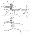
- Figure 3 is a view of various components of a second embodiment of a latch arrangement according to the present invention;
- Figure 4 is a view taken in the direction of arrow A of figure 3; and
- Figure 5 is a view similar to figure 4 including a door and with some of the components of the latch arrangement shown in an abnormally deformed position.
-
- With reference to figures 1 and 2 there is shown a
latch arrangement 10 for use with a car side door thelatch arrangement 10 including a latch mechanism 12 (only part of which is shown), a transmission path 14 and a release means in the form of an inside door handle 16 (shown schematically). - Typically the door would be hinged at a front edge, though in further embodiments this need not be the case.
- The latch mechanism 12 includes a
housing 18 on which is pivoted latch mechanism insiderelease lever 20. - The
housing 18 further includes a latch bolt (not shown) for engagement with a striker pin secured to fixed structure of the car such as a B post or a C post. The latch bolt is retained in a close position by a pawl (not shown), thus allowing the latch arrangement to secure the door in a closed position. The pawl is operably connected to the latch mechanism insiderelease lever 20 via transmission elements (not shown) of the transmission path 14. - A
rod 22 is pivotally connected atend 22A viapivot 24 to insidedoor handle 16. - At end 22B, the
rod 22 is bent at 90° and includesfirst abutment 26,second abutment 28 andthird abutment 30 all being provided on the bent portion of therod 22. End 22B passes through a hole in latch mechanism insiderelease lever 20. - A resilient means in the form of a
spring 32 is mounted on end 22B and abutsthird abutment 30 and the edge of the hole in the latch mechanism insiderelease lever 20. - When installed, the
spring 32 is under compression that such thatsecond abutment 28 is biased into engagement with latch mechanism insiderelease lever 20 as shown in figure 1. - The latch mechanism 12 can be locked and unlocked by actuation of
lock lever 34. Whenlock lever 34 is in position U, as shown in figure 1, the latch mechanism 12 is unlocked and whenlock lever 34 is in position L, as shown in figure 1, the latch mechanism is locked. Locking can be effected bylock lever 34 providing a break in the transmission path whereby operation ofinside door handle 16 is possible but has no effect or bylock lever 34 providing a block in the trammission path whereby operation ofinside door handle 16 is prevented thus similarly leaving the door in a locked condition. - Normal operation of
inside door handle 16, when the latch mechanism is unlocked causes movement ofrod 22 in the direction of arrow B resulting in unlatching of the Latch mechanism. - It should be noted that transmission elements of the transmission path include
rod 22, insiderelease lever 20, the pawl and the blocking or breaking element (not shown) connected tolock lever 34. It is the various elements of the transmission path which connect the inside door handle ultimately to the latch bolt. - The
latch assembly 10 is contained within a door 50, having a door outer skin 51. Connected to an inner portion of the door skin 51 is adefamation abutment 52. In thiscase deformation 52 is solely provided for transmitting an impact on the door skin 51 to the transmission path. However, in further embodiment the deformation abutment can form part of further components, for example, window regulator rails. - In the event of a side impact on the door 50 by say another vehicle, the door skin is deformed inwardly causing the deformation abutment to also move inwardly and initially contact the
rod 22, following which aspring 32 is compressed allowingfirst abutment 26 to movelock lever 34 from the unlocked position U to the locked position L thus locking the door (see figure 2). - Any subsequent deformation of the latch arrangement, in particular deformation of the
rod 22 which puts the rod into tension and thus potentially causes rotation of the latch mechanism insiderelease lever 20 will not unlatch the door since the initial deformation put the door into a locked condition. It can be seen that the initial deformation which puts the latch mechanism into a locked condition is allowed for by resilient deformation ofspring 32. - It should be noted from figures 1 and 2 that a
contact abutment 52 is located proximal end 22b ofrod 22, ie proximal the latch mechanism 12. - With reference to figures 3 to 5 there is shown a second embodiment of a latch arrangement which includes a
latch mechanism 112, atransmission path 114, ahousing 118, a latch mechanism insiderelease lever 120, arod 122 and aspring 132. The latch mechanism further includes arelease lever 140 operably situated between the latch mechanism insiderelease lever 120 and the pawl (not shown).Release lever 140 is pivotally mounted aboutpivot 142 and includes a tab 144. The latch arrangement 110 is mounted within adoor 146 which defines a door plane D.P. Normal operation of the latch arrangement causesrod 122 to move in the direction of arrow C within a movement plane M.P which is generally parallel to the door plane D.P. - During a side impact on the door, initial deformation causes the latch mechanism inside
release lever 120 and therod 122 to move in the direction of arrow E of figure 5 causing thespring 132 to compress. This results inend 122A becoming missaligned with tab 144 and thus any subsequent deformation which would cause therod 122 to go into tension would cause latch mechanism insiderelease lever 20 to rotate aboutpivot 148 in the direction of arrow R of figure 1. However sinceend 122A is missaligned with tab 144 the latch mechanism is not caused to unlatch. This misalignment ofend 122A and tab 144 provides a break in the transmission path thus locking the door from the inside of the vehicle. - The invention is not limited to use with a transmission path connecting a latch bolt with an inside handle of a door, in particular the invention could be used in conjunction with an outside door handle of a vehicle.
- Furthermore, when the latch arrangement includes a first transmission path between the latch bolt and an inside door handle and a second transmission path between the latch bolt and outside door handle, initial deformation of the latch arrangement could be arranged to cause a first break or block in the in the first transmission path and a second break or block in the second transmission path.
- When part of the first transmission path is common with a part of the second transmission path, the break or block could be provided in the common part of the transmission path thus only requiring one block or break to secure the door from opening.
- It should be noted that the invention is not limited to latch bolts in the form of rotating claws.
- It should also be noted that a car door can be locked whereby operation of an outside door handle does not open the latch, or whereby operation of an inside door handle does not operate the latch (also known as a child safety condition) or the door can be locked such that operation of either the outside or inside door handle does not operate the latch (known as super locked or dead locked condition) and the present invention is applicable to all these types of locking.
- Furthermore locking can be effected by providing a break between a door handle and the claw such that the door handle 'free wheels' without opening the latch, or locking can be provided by creating a block between the door handle and claw such that the block prevents movement of the door handle and the present invention is applicable to 'break' or `block' type locking. The
lock lever 34 can either provide such a break or block directly or can act on further levers or the like which themselves provide the break or block.
Claims (12)
- A latch arrangement (100) including a latch bolt connected to release means by a transmission path (114), normal actuation of the release means causing unlatching of the latch arrangement, characterised in that the transmission path (114) is adapted such that abnormal initial deformation of part of the transmission path causes a break in the transmission path such that further abnormal deformation of that part of the latch arrangement on the release means side of the break does not release the latch, wherein the transmission path (114) includes a plurality of transmission elements (122, 122A, 144) in which the break is provided for by misalignment of adjacent transmission elements (122a, 144) which is allowed for by resilient movement of a resilient means (132).
- A latch arrangement as defined in Claim 1 in which the latch arrangement is lockable by provision of a normal break in the transmission path and the initial deformation causes locking via the normal break.
- A latch arrangement as defined in Claim 2 which is normally lockable via movement of a lock element from an unlocked position to a locked position, abnormal initial deformation of the latch arrangement causing a transmission element of the transmission path to move the lock element to its locked position.
- A latch arrangement as defined in any preceding claim in which the transmission element is a rod (122).
- A latch arrangement as defined in Claim 4 in which the rod is connected between a latch mechanism (112) including the latch bolt and a handle of a door.
- A latch arrangement as defined in any preceding Claim in which one of the adjacent transmission elements is a transmission lever (140) directly connected at a first end of a rod (122), a second end of the rod being connected to a handle of a door.
- A latch arrangement as defined in any preceding Claim further including a further release means connected to the latch bolt by a further transmission path, normal actuation of the further release means causing unlatching of the latch arrangement, the further transmission path being adapted such that abnormal initial deformation of part of the further transmission path causes a further break in the further transmission path such that said further abnormal deformation of that part of the latch arrangement on the further release means side of the further break does not release the latch.
- A latch arrangement as defined in Claim 7 in which the transmission path and further transmission path have a common portion and the break is operably situated within the common portion.
- A latch arrangement (10) including a latch bolt connected to release means by a transmission path (14), normal actuation of the release means causing unlatching of the latch arrangement, the transmission path being adapted such that abnormal initial deformation of part of the transmission path causes a break or a block in the transmission path such that further abnormal deformation of that part of the latch arrangement on the release means side of the break or the block does not release the latch, the latch arrangement being normally lockable via movement of a lock element (34) from an unlocked position to a locked position, so as to provide a normal break or normal block in the transmission path, said abnormal initial deformation causing locking via the normal break or normal block by causing a transmission element of the transmission path (14) to move the lock element (34) to its locked position and wherein the abnormal movement of the transmission element is allowed for by resilient movement of a resilient means (32).
- A door (50) defining a door plane (146), the door including a latch arrangement (10; 1 10) as defined in any preceding Claim in which a transmission element of the transmission path normally moves in a movement plane substantially parallel to the door plane, abnormal deformation of the latch arrangement being capable of causing the transmission element to move out of its movement plane.
- A latch arrangement as defined at any one of Claims 1 to 9 for inclusion in a side door of a car.
- A door as defined in Claim 10 in which the door is a side door of a car.
Applications Claiming Priority (2)
| Application Number | Priority Date | Filing Date | Title |
|---|---|---|---|
| GB9915767 | 1999-07-07 | ||
| GBGB9915767.9A GB9915767D0 (en) | 1999-07-07 | 1999-07-07 | Latch arrangement |
Publications (2)
| Publication Number | Publication Date |
|---|---|
| EP1069267A1 EP1069267A1 (en) | 2001-01-17 |
| EP1069267B1 true EP1069267B1 (en) | 2005-02-02 |
Family
ID=10856713
Family Applications (1)
| Application Number | Title | Priority Date | Filing Date |
|---|---|---|---|
| EP20000305756 Expired - Lifetime EP1069267B1 (en) | 1999-07-07 | 2000-07-07 | Latch arrangement |
Country Status (3)
| Country | Link |
|---|---|
| EP (1) | EP1069267B1 (en) |
| DE (1) | DE60017832T2 (en) |
| GB (1) | GB9915767D0 (en) |
Family Cites Families (4)
| Publication number | Priority date | Publication date | Assignee | Title |
|---|---|---|---|---|
| JPS6055672B2 (en) * | 1979-05-10 | 1985-12-06 | アイシン精機株式会社 | Automobile door lock device |
| JPH064988B2 (en) * | 1988-10-11 | 1994-01-19 | マツダ株式会社 | Vehicle door lock device |
| JPH03221681A (en) * | 1990-01-25 | 1991-09-30 | Nissan Motor Co Ltd | Automotive door lock system |
| WO1995032349A1 (en) * | 1994-05-25 | 1995-11-30 | Atoma International, Inc. | V-link release mechanism for automobile door latches |
-
1999
- 1999-07-07 GB GBGB9915767.9A patent/GB9915767D0/en not_active Ceased
-
2000
- 2000-07-07 DE DE2000617832 patent/DE60017832T2/en not_active Expired - Fee Related
- 2000-07-07 EP EP20000305756 patent/EP1069267B1/en not_active Expired - Lifetime
Also Published As
| Publication number | Publication date |
|---|---|
| EP1069267A1 (en) | 2001-01-17 |
| DE60017832T2 (en) | 2006-05-11 |
| GB9915767D0 (en) | 1999-09-08 |
| DE60017832D1 (en) | 2005-03-10 |
Similar Documents
| Publication | Publication Date | Title |
|---|---|---|
| US5494322A (en) | Power-actuated motor-vehicle door latch with child-safety cutout | |
| US4364249A (en) | Central door-lock system for motor vehicles | |
| US7607702B2 (en) | Inertia catch for a vehicle latch | |
| US5069491A (en) | Vehicle door lock system | |
| US5117665A (en) | Vehicle door lock system | |
| US5961163A (en) | Motor-vehicle door latch with antitheft protection | |
| US6045168A (en) | Door latch with improved double lock | |
| US20030234544A1 (en) | Emergency-locking latch assembly for a vehicle door | |
| EP1375794A2 (en) | Inertia locking mechanism | |
| CN108278053B (en) | Free-wheeling inertia mechanism for closure latch assembly | |
| US20030218340A1 (en) | Latch arrangement | |
| US20030214137A1 (en) | Vehicle latch assembly having modular components | |
| EP1121503B8 (en) | Door latch | |
| KR101163780B1 (en) | Motor vehicle door lock | |
| GB2361675A (en) | Latching arrangement of passenger door | |
| US20010015558A1 (en) | Latch mechanism | |
| US4097077A (en) | Closure latch | |
| EP1069267B1 (en) | Latch arrangement | |
| US20180313118A1 (en) | Vehicle door latch apparatus | |
| EP0021743B1 (en) | Lock for a tiltable truck cab and vehicles including such locks | |
| GB2339831A (en) | Vehicle door latch | |
| GB2301143A (en) | A motor vehicle door lock | |
| EP1375793A2 (en) | Assembly for opening, locking and unlocking of vehicle wings | |
| MXPA96001946A (en) | Automo vehicle door closure | |
| US20040160066A1 (en) | Door latch mechanism |
Legal Events
| Date | Code | Title | Description |
|---|---|---|---|
| PUAI | Public reference made under article 153(3) epc to a published international application that has entered the european phase |
Free format text: ORIGINAL CODE: 0009012 |
|
| AK | Designated contracting states |
Kind code of ref document: A1 Designated state(s): DE FR GB |
|
| AX | Request for extension of the european patent |
Free format text: AL;LT;LV;MK;RO;SI |
|
| RIN1 | Information on inventor provided before grant (corrected) |
Inventor name: FISHER,SYDNEY EDWARD MERITOR LIGHT VEH.SYST.UK LT Inventor name: KEYES, GREGORY MERITOR LIGHT VEH. SYST. UK LTD Inventor name: FAIREY, ANDREW J. MERITOR LIGHT VEH. SYST. UK LTD Inventor name: FAUVEAU, AXEL MERITOR LIGHT VEH. SYST. UK LTD Inventor name: SPURR, NIGEL V. MERITOR LIGHT VEH. SYST. UK LTD Inventor name: WATSON, RICHARD MERITOR LIGHT VEH. SYST. UK LTD Inventor name: KALSI, GURBINDER S. MERITOR LIGHT VEH. SYST.UK LTD |
|
| 17P | Request for examination filed |
Effective date: 20010706 |
|
| AKX | Designation fees paid |
Free format text: DE FR GB |
|
| RAP1 | Party data changed (applicant data changed or rights of an application transferred) |
Owner name: ARVINMERITOR LIGHT VEHICLE SYSTEMS (UK) LTD |
|
| 17Q | First examination report despatched |
Effective date: 20030908 |
|
| GRAP | Despatch of communication of intention to grant a patent |
Free format text: ORIGINAL CODE: EPIDOSNIGR1 |
|
| GRAS | Grant fee paid |
Free format text: ORIGINAL CODE: EPIDOSNIGR3 |
|
| GRAA | (expected) grant |
Free format text: ORIGINAL CODE: 0009210 |
|
| AK | Designated contracting states |
Kind code of ref document: B1 Designated state(s): DE FR GB |
|
| REG | Reference to a national code |
Ref country code: GB Ref legal event code: FG4D |
|
| REF | Corresponds to: |
Ref document number: 60017832 Country of ref document: DE Date of ref document: 20050310 Kind code of ref document: P |
|
| ET | Fr: translation filed | ||
| PLBE | No opposition filed within time limit |
Free format text: ORIGINAL CODE: 0009261 |
|
| STAA | Information on the status of an ep patent application or granted ep patent |
Free format text: STATUS: NO OPPOSITION FILED WITHIN TIME LIMIT |
|
| 26N | No opposition filed |
Effective date: 20051103 |
|
| PGFP | Annual fee paid to national office [announced via postgrant information from national office to epo] |
Ref country code: GB Payment date: 20060830 Year of fee payment: 7 |
|
| PGFP | Annual fee paid to national office [announced via postgrant information from national office to epo] |
Ref country code: FR Payment date: 20060908 Year of fee payment: 7 |
|
| PGFP | Annual fee paid to national office [announced via postgrant information from national office to epo] |
Ref country code: DE Payment date: 20060914 Year of fee payment: 7 |
|
| GBPC | Gb: european patent ceased through non-payment of renewal fee |
Effective date: 20070707 |
|
| PG25 | Lapsed in a contracting state [announced via postgrant information from national office to epo] |
Ref country code: DE Free format text: LAPSE BECAUSE OF NON-PAYMENT OF DUE FEES Effective date: 20080201 |
|
| PG25 | Lapsed in a contracting state [announced via postgrant information from national office to epo] |
Ref country code: GB Free format text: LAPSE BECAUSE OF NON-PAYMENT OF DUE FEES Effective date: 20070707 |
|
| REG | Reference to a national code |
Ref country code: FR Ref legal event code: ST Effective date: 20080331 |
|
| PG25 | Lapsed in a contracting state [announced via postgrant information from national office to epo] |
Ref country code: FR Free format text: LAPSE BECAUSE OF NON-PAYMENT OF DUE FEES Effective date: 20070731 |
|
| REG | Reference to a national code |
Ref country code: GB Ref legal event code: 732E |