EP1069262A2 - A vehicle parking apparatus - Google Patents
A vehicle parking apparatus Download PDFInfo
- Publication number
- EP1069262A2 EP1069262A2 EP00650079A EP00650079A EP1069262A2 EP 1069262 A2 EP1069262 A2 EP 1069262A2 EP 00650079 A EP00650079 A EP 00650079A EP 00650079 A EP00650079 A EP 00650079A EP 1069262 A2 EP1069262 A2 EP 1069262A2
- Authority
- EP
- European Patent Office
- Prior art keywords
- platform
- vehicle
- elevator platform
- pillars
- support
- Prior art date
- Legal status (The legal status is an assumption and is not a legal conclusion. Google has not performed a legal analysis and makes no representation as to the accuracy of the status listed.)
- Withdrawn
Links
- 230000005484 gravity Effects 0.000 claims description 9
- 230000003068 static effect Effects 0.000 claims description 4
- 238000005096 rolling process Methods 0.000 claims description 3
- 238000010276 construction Methods 0.000 description 9
- 238000004873 anchoring Methods 0.000 description 2
- 238000004519 manufacturing process Methods 0.000 description 2
- 239000004677 Nylon Substances 0.000 description 1
- 208000027418 Wounds and injury Diseases 0.000 description 1
- 230000006378 damage Effects 0.000 description 1
- 238000011065 in-situ storage Methods 0.000 description 1
- 208000014674 injury Diseases 0.000 description 1
- 229920001778 nylon Polymers 0.000 description 1
Images


Classifications
-
- E—FIXED CONSTRUCTIONS
- E04—BUILDING
- E04H—BUILDINGS OR LIKE STRUCTURES FOR PARTICULAR PURPOSES; SWIMMING OR SPLASH BATHS OR POOLS; MASTS; FENCING; TENTS OR CANOPIES, IN GENERAL
- E04H6/00—Buildings for parking cars, rolling-stock, aircraft, vessels or like vehicles, e.g. garages
- E04H6/02—Small garages, e.g. for one or two cars
- E04H6/06—Small garages, e.g. for one or two cars with means for shifting or lifting vehicles
-
- B—PERFORMING OPERATIONS; TRANSPORTING
- B66—HOISTING; LIFTING; HAULING
- B66F—HOISTING, LIFTING, HAULING OR PUSHING, NOT OTHERWISE PROVIDED FOR, e.g. DEVICES WHICH APPLY A LIFTING OR PUSHING FORCE DIRECTLY TO THE SURFACE OF A LOAD
- B66F7/00—Lifting frames, e.g. for lifting vehicles; Platform lifts
- B66F7/02—Lifting frames, e.g. for lifting vehicles; Platform lifts with platforms suspended from ropes, cables, or chains or screws and movable along pillars
-
- B—PERFORMING OPERATIONS; TRANSPORTING
- B66—HOISTING; LIFTING; HAULING
- B66F—HOISTING, LIFTING, HAULING OR PUSHING, NOT OTHERWISE PROVIDED FOR, e.g. DEVICES WHICH APPLY A LIFTING OR PUSHING FORCE DIRECTLY TO THE SURFACE OF A LOAD
- B66F7/00—Lifting frames, e.g. for lifting vehicles; Platform lifts
- B66F7/28—Constructional details, e.g. end stops, pivoting supporting members, sliding runners adjustable to load dimensions
Definitions
- This invention relates to a vehicle parking apparatus.
- the invention particularly relates to a vertical lift double deck vehicle parking apparatus comprising a ground engaging support, a vehicle elevator platform movable on the support between a lowered position and a raised position, the lowered position being such that a vehicle can be driven on to the elevator platform for parking on the elevator platform, and the raised position being such that another vehicle can be driven and parked beneath the elevator platform, and drive means operable for movement of the elevator platform on the support.
- a vertical lift double deck vehicle parking apparatus comprising a ground engaging support, a vehicle elevator platform movable on the support between a lowered position and a raised position, the lowered position being such that a vehicle can be driven on to the elevator platform for parking on the elevator platform, and the raised position being such that another vehicle can be driven and parked beneath the elevator platform, and drive means operable for movement of the elevator platform on the support.
- This type of apparatus is described, for example, in Patent Specification US 3,750,899.
- An example of a triple deck vertical lift vehicle parking apparatus is described in US 5,035,562.
- the present invention is directed towards overcoming these problems.
- the ground engaging support comprises a pair of upright pillars spaced-apart sufficiently to allow a vehicle be driven between the pillars, the vehicle elevator platform being mounted between the pillars on a cross beam which extends between the pillars, each end of the cross beam being vertically movable on the associated pillar with which it is engaged, the platform extending in cantilevered fashion on either side of the cross beam.
- the invention provides a parking apparatus of relatively simple construction facilitating manufacture and reliability in operation and also allowing good access to vehicles using the apparatus.
- each pillar is an upstanding C-shaped channel arranged such that channel openings of each pillar face each other, and ends of the cross beam engage through said openings with associated carriages which are vertically movable within the channel of each pillar.
- support legs may be provided at a lower end of each pillar so that the apparatus is free-standing.
- Each support leg may be provided with means for anchoring the support leg to the ground.
- anchoring means may for example comprise a slot for reception of an anchor bolt.
- each end of the platform is adapted to allow movement of a vehicle onto the platform when the platform is in the lowered position.
- a user can drive a vehicle onto or off the platform at either end of the platform.
- the pillars are interconnected at their lower ends.
- the pillars may be interconnected by a base plate such that in use the lowermost vehicle may rest on the base plate to provide additional security and stability to the apparatus.
- the elevator platform is curved, having a raised central portion with downwardly and outwardly sloping end portions. This construction advantageously facilitates maintaining a vehicle in position on the elevator platform by its own weight, resisting any tendency of the vehicle to roll on the elevator platform.
- vehicle stop means is provided on the elevator platform.
- the stop means may conveniently be provided by stop flaps at each end of the vehicle elevator platform. At least one of these stop flaps should be movable between a lowered position which allows a vehicle to drive on or off the vehicle elevator platform and a raised position extending upwardly of the vehicle elevator platform to prevent a vehicle rolling off the vehicle elevator platform.
- both of the stop flaps are movable, this construction allowing a vehicle to drive onto or off the platform at either end.
- the stop flaps are movable under gravity between a lowered release position and a raised engaged position.
- the flaps may be pivotally mounted on the vehicle support platform with associated actuating means being provided, said actuating means being movable under gravity on the vehicle support platform to pivot the associated stop flaps.
- This actuating means may be provided by a slide block which is vertically movable on the vehicle support platform between upper and lower flap engaging positions, the slide block being held in the upper position by the ground when the vehicle support platform is in the lowered position and the slideblock being free to fall under gravity into the lower position when the vehicle support platform is raised to pivot the flap into the engaged position.
- the drive means has an electric motor for operation of the drive means.
- the electric motor is preferably connected to a battery power supply. Thus it can be operated even in the event of mains power failure.
- the apparatus includes a battery charger.
- the battery charger preferably includes a solar panel mounted on the support for recharging the battery.
- the apparatus has a fully independent power supply.
- the vehicle elevator platform is mounted on a pair of carriages vertically movable on the pillars, a static drive chain being mounted on each pillar between a bottom and a top of the pillar, a drive sprocket engaged with the chain, the drive sprocket carried on a drive shaft mounted on the vehicle support platform, said drive shaft being connected to the drive motor, operation of the drive motor rotating the drive shaft and drive sprocket to move the drive sprocket along the chain and hence raise or lower the vehicle elevator platform.
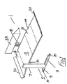
- the apparatus 1 comprises a ground engaging support 2 with a vehicle elevator platform 3 movable on the support 2 between a lowered ground-engaging position and a raised position as shown in Fig. 1.
- the lowered position is such that a car 5 can be driven onto the elevator platform 3 from either end as shown in Fig. 7, and parked on the elevator platform 3 as shown in Figs. 8 and 9.
- Drive means described later, is then operable to raise the elevator platform 3 on the support 2 to the raised position, as shown in Fig. 10.
- a second car 5 can be parked beneath the vehicle elevator platform 3 as shown in Fig. 10.
- the support 2 comprises a pair of upright pillars 7, 8 spaced-apart to allow a car 5 be driven between the pillars 7,8.
- the vehicle elevator platform 3 is slideably mounted between the pillars 7, 8.
- Support legs 9 are provided at the lower end of each pillar 2. Slots 10 for reception of anchor bolts are provided at each end of the legs 9 so that the legs 9 can be bolted to the ground if desired.
- the lower ends of the pillars 2 and legs 9 are interconnected by a base plate which extends between the pillars 7,8.
- the elevator platform 3 is curved between its front and rear ends having a raised central portion 12 with downwardly and outwardly sloping end portions 13, 14. Most advantageously a car 5 is maintained in position on the platform 3 by its own weight, the vehicle wheels being positioned on either side of the central portion 12 when parking the car 5 on the platform 3.
- the platform 3 is supported on a cross-beam 16 mounted between the pillars 7, 8.
- a pair of longitudinal members 17, 18 are mounted on the cross-beam 16.
- a number of transverse ribs 19 extend between the longitudinal members 17, 18 and support the platform 3 thereon.
- a stop flap 20 is pivotally mounted by a tubular housing 21 on a pivot bar 22.
- a counter balance 23 projects inwardly on the housing 21 at an opposite side to the flap 20 and engages a slide block 24 which is vertically slideable on the platform 3 under gravity between a raised position shown in Fig. 6A and a lowered position shown in Fig. 6B.
- the ground 25 engages the block 24 and urges the block 24 upwardly to the raised position so that the flap 20 is extended and forms an extension or lead-in ramp onto the platform 3.
- the block 24 can fall under gravity as shown in Fig. 6B engaging the counter balance 23 to pivot the flap 20 upwardly into an engaged position projecting upwardly of the platform 3 as shown in Fig. 6B.
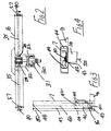
- the drive means has an electric motor 30 an associated reduction gear-box 31.
- the electric motor 30 is connected to a battery power supply (not shown).
- the battery has a charger which is operated by means of a solar panel 33, mounted on the pillar 8.
- the motor 30 and gear box 31 are mounted on the cross-beam 16.
- Drive chains 32 at each side of the gearbox 31 connect between the gearbox 31 and drive-shafts 35 mounted on the beam 16 by bearings 37, 38.
- a drive sprocket 40 is mounted at an outer end of each drive shaft 35.
- a platform carriage 42 is mounted within each pillar 7, 8 which is of C-shaped channel section.
- Each outer end of the cross beam 16 engages through an inwardly facing opening 43 of a channel section pillar 7, 8 with an associated carriage 42 which is vertically movable within the pillar 7. 8.
- Wheels 44 on the carriage 42 engage inner faces of the pillar 7, 8 for rolling the carriage 42 up and down on the pillar 7, 8.
- a static drive chain 46 is mounted within each pillar 7, 8 extending between a top and a bottom of the pillar 7,8 to which it is attached at 48, 49.
- the chain 46 is led around a guide sprocket 41 which is fixed to the carriage 42 and serves both to increase the contact area of the roller chain 46 and drive sprocket 40 and also ensures that this contact is maintained throughout the operation cycle.
- a user operates the electric motor to rotate the shafts 35 and hence drive sprockets 40, which then climbs up and down the chains 46.
- the electric motor maintains an output until the platform 3 reaches its uppermost position at which point an electromechanical relay 82 de-activates the electric motor 30 and activates an electromagnetic locking device within the electric motor to insure the system remains static until the locking device is de-activated.
- the gear ratio of the gear box 31 is 288:1 the platform 3 will not move unless driven thus the platform 3 and car 5 will remain elevated irrespective of the condition of the electromechanical lock.
- the motor is again operated to lower the platform 3.
- Figs. 7 to 10 show the sequence for driving a car 5 onto the platform 3 which is then raised and then a second car 5 can be driven in under the platform 3.
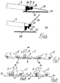
- Figs. 11 to 13 there is shown an alternative construction of stop flap for the platform 3.
- the stop flap 20 has a raising mechanism indicated generally by the reference numeral 50 which raises the stop flap 20 from a lowered position shown in Fig. 11 when the platform 3 is lowered to ground level for loading the platform 3 and a raised position as shown in Fig. 12 when the platform 3 is raised clear of the ground.
- the mechanism 50 comprises a lever 51 connected on an underside of the platform 3 by a mounting bracket 52, the lever 51 engaging the mounting bracket 52 by means of a pivot pin 53.
- a spring 54 extending between the top of the lever 51 and an underside of the platform 3 urges the lever 51 downwardly away from the platform 3.
- the lever 51 connects with an intermediate link 56 via pivot 57.
- This intermediate link 56 in turn connects through pivot 58 with an outer link 59 which is pivoted at the outer end of the platform 3, on the pivot bar 22, and has a pusher arm 60 attached so that movement of the link 59 will raise the pusher arm 60 as shown in Fig. 12 to elevate the hinged stop flap 20 into the raised car retaining position.
- Nylon rollers 62 are mounted on a spindle 63 which is rotatable on the intermediate link 56.
- the linkage 50 In use with the platform 3 in the lowered position shown in Fig. 11 the linkage 50 is collapsed up against an underside of the platform 3 and the flap 20 is lowered to form a ramp for loading a car on the platform 3. As the platform 3 is subsequently raised as previously described, the linkage 50 falls partly under gravity and partly under the action of the spring 54 away from the platform 3. Movement of the link 59 pivots the pusher arm 60 upwardly which pushes the flap 20 into the raised position and holds the flap 20 in the raised position. Upon subsequent lowering of the platform 3, the rollers 62 engaged the ground first and facilitate folding of the linkage 50 in a controlled manner into the retracted position shown in Fig. 11. Thus the flap 20 is lowered in a controlled manner to the ground for unloading the car from the platform 3. It will be appreciated that the linkage 50 provides good control of the flap 20 at all times to avoid injury to an operator.
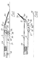
- FIG. 14 and 15 there is shown another stop flap construction indicated generally by the reference numeral 80 which is largely similar to that described with reference to Figs. 11 to 13 and like parts are assigned the same reference numerals.
- a tubular bearing collar 55 is provided at an inner end of the lever 51 which rotatably engages the pivot pin 53 which in turn is supported between a pair of downwardly depending mounting brackets 52 on an underside of the platform 3.
- a similar bearing collar 55 is provided at the outer end of the lever 51 for rotatable engagement with the pivot 57.
- a lower end of the spring 54 seats around an upstanding spigot 54 on the lever 51.
- An upper end of the spring 54 is housed within a socket 65 of a spring mounting bracket 66 on an underside of the platform 3.
- a tubular bushing 67 at an inner end of the outer link 59 rotatably mounts the outer link 59 on the pivot pin 58.
- a tubular bearing sleeve 68 mounted on a top of the outer link 59 intermediate the ends of the outer link 59 rotatably receives a central portion of the pivot bar 22 which is supported between a pair of spaced-apart tubular housings 21 at an outer end of the platform 3.
- Operation of the flap mechanism 80 is similar to that of the flap mechanism shown in Figs. 11 to 13.
- the flap 20 is shown in broken outline in Fig. 14 in a raised position which occurs when the platform 3 is raised dear of the ground allowing the linkage 80 to drop down under gravity and spring 54 action, thus pivoting the outer link 59 and pusher arm 60 about the pivot bar 22 to raise the stop flap 20.
- the linkage 80 folds upwardly against an underside of the platform 3 when the platform 3 is lowered to pivot the flap 20 downwardly in a controlled manner to form a loading/unloading ramp at an end of the platform 3.
- a transport trailer indicated generally by the reference numeral 70 for the parking apparatus The trailer 70 comprises a chassis 71 mounted on wheels 72 and having a tow hitch 73 for trailing behind a vehicle.
- the trailer chassis 71 is positioned between the pillars 7, 8 with the platform 3 in a raised position as shown in Fig. 14.
- the platform 3 is then lowered to engage the chassis 71 and raise the support legs 9 and pillars 7, 8 dear of the ground.
- Clamps (not shown) are then used to secure the apparatus 1 on the trailer 70.
- the apparatus 1 can thus be delivered by the trailer 70 to a site for use. It will be appreciated that the trailer 70 is easily manipulated even in relatively restricted areas to facilitate positioning the apparatus 1 at a desired position for use.
- the damps are released, the platform 3 is raised and the trailer 70 is withdrawn from beneath the platform to leave the apparatus 1 in situ.
Landscapes
- Engineering & Computer Science (AREA)
- Structural Engineering (AREA)
- Architecture (AREA)
- Life Sciences & Earth Sciences (AREA)
- Geology (AREA)
- Mechanical Engineering (AREA)
- Civil Engineering (AREA)
- Vehicle Step Arrangements And Article Storage (AREA)
Abstract
Description
- This invention relates to a vehicle parking apparatus.
- It is an object of the invention to provide an improved parking capability particularly in areas where space is very limited.
- The invention particularly relates to a vertical lift double deck vehicle parking apparatus comprising a ground engaging support, a vehicle elevator platform movable on the support between a lowered position and a raised position, the lowered position being such that a vehicle can be driven on to the elevator platform for parking on the elevator platform, and the raised position being such that another vehicle can be driven and parked beneath the elevator platform, and drive means operable for movement of the elevator platform on the support. This type of apparatus is described, for example, in Patent Specification US 3,750,899. An example of a triple deck vertical lift vehicle parking apparatus is described in US 5,035,562. These parking apparatus use hydraulic systems incorporating rams to raise and lower the platform or platforms. The constructions can be somewhat complex and heavy which is undesirable from a manufacturing and from a transport point of view. Also, the employment of bracing bars on the support structure for the platform can inhibit access to a vehicle using the parking apparatus.
- The present invention is directed towards overcoming these problems.
- The invention is characterised in that the ground engaging support comprises a pair of upright pillars spaced-apart sufficiently to allow a vehicle be driven between the pillars, the vehicle elevator platform being mounted between the pillars on a cross beam which extends between the pillars, each end of the cross beam being vertically movable on the associated pillar with which it is engaged, the platform extending in cantilevered fashion on either side of the cross beam. Advantageously, the invention provides a parking apparatus of relatively simple construction facilitating manufacture and reliability in operation and also allowing good access to vehicles using the apparatus.
- In a particularly preferred embodiment, each pillar is an upstanding C-shaped channel arranged such that channel openings of each pillar face each other, and ends of the cross beam engage through said openings with associated carriages which are vertically movable within the channel of each pillar.
- Conveniently, support legs may be provided at a lower end of each pillar so that the apparatus is free-standing.
- Each support leg may be provided with means for anchoring the support leg to the ground. Such anchoring means may for example comprise a slot for reception of an anchor bolt.
- In a particularly preferred embodiment, each end of the platform is adapted to allow movement of a vehicle onto the platform when the platform is in the lowered position. Thus conveniently, a user can drive a vehicle onto or off the platform at either end of the platform.
- In another embodiment the pillars are interconnected at their lower ends. The pillars may be interconnected by a base plate such that in use the lowermost vehicle may rest on the base plate to provide additional security and stability to the apparatus.
- In a further embodiment, the elevator platform is curved, having a raised central portion with downwardly and outwardly sloping end portions. This construction advantageously facilitates maintaining a vehicle in position on the elevator platform by its own weight, resisting any tendency of the vehicle to roll on the elevator platform.
- Preferably vehicle stop means is provided on the elevator platform. The stop means may conveniently be provided by stop flaps at each end of the vehicle elevator platform. At least one of these stop flaps should be movable between a lowered position which allows a vehicle to drive on or off the vehicle elevator platform and a raised position extending upwardly of the vehicle elevator platform to prevent a vehicle rolling off the vehicle elevator platform.
- Preferably both of the stop flaps are movable, this construction allowing a vehicle to drive onto or off the platform at either end.
- Conveniently, the stop flaps are movable under gravity between a lowered release position and a raised engaged position. The flaps may be pivotally mounted on the vehicle support platform with associated actuating means being provided, said actuating means being movable under gravity on the vehicle support platform to pivot the associated stop flaps. This actuating means may be provided by a slide block which is vertically movable on the vehicle support platform between upper and lower flap engaging positions, the slide block being held in the upper position by the ground when the vehicle support platform is in the lowered position and the slideblock being free to fall under gravity into the lower position when the vehicle support platform is raised to pivot the flap into the engaged position.
- In a preferred embodiment, the drive means has an electric motor for operation of the drive means. The electric motor is preferably connected to a battery power supply. Thus it can be operated even in the event of mains power failure.
- In a further embodiment, the apparatus includes a battery charger. The battery charger preferably includes a solar panel mounted on the support for recharging the battery. Thus the apparatus has a fully independent power supply.
- In another embodiment, the vehicle elevator platform is mounted on a pair of carriages vertically movable on the pillars, a static drive chain being mounted on each pillar between a bottom and a top of the pillar, a drive sprocket engaged with the chain, the drive sprocket carried on a drive shaft mounted on the vehicle support platform, said drive shaft being connected to the drive motor, operation of the drive motor rotating the drive shaft and drive sprocket to move the drive sprocket along the chain and hence raise or lower the vehicle elevator platform.
- The invention will be more dearly understood by the following description of some embodiments thereof, given by way of example only, with reference to the accompanying drawings, in which:
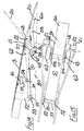
- Fig. 1 is a perspective view of a vehicle parking apparatus according to the invention;
- Fig. 2 is a plan view of portion of a drive means for a vehicle elevator platform of the apparatus;
- Fig. 3 is an elevational view of portion of the drive means;
- Fig. 4 is a detail plan view of portion of the drive means;
- Fig. 5 is an exploded perspective view of a vehicle elevator platform of the apparatus;
- Fig. 6 is a detail sectional elevational view of a stop-flap mounted at one end of the vehicle elevator platform;
- Fig. 7 is an elevational view of the vehicle elevator platform, shown in use;
- Fig. 8 is an elevational view of the vehicle support platform, shown with a car mounted on the platform;
- Fig. 9 is a view similar to Fig. 8 showing the car mounted in a different orientation on the vehicle elevator platform;
- Fig. 10 is an elevational view of the apparatus with the vehicle elevator platform raised and supporting a car with a further car mounted below the vehicle elevator platform.
- Fig. 11 is a a detail diagrammatic elevational view of another stop-flap arrangement at an end of the vehicle elevator platform;
- Fig. 12 is a view similar to Fig. 11 showing the stop-flap in another position of use;
- Fig. 13 is a plan view of the stop-flap assembly;
- Fig. 14 is a detail elevational view similar to Fig. 11 showing another stop-flap construction;
- Fig. 15 is a detail underneath plan view of the stop flap construction shown in Fig. 14; and
- Fig. 16 is a side elevational view of the vehicle elevator platform with an associated transport trailer.
-
- Referring to the drawings, there is illustrated a vehicle parking apparatus according to the invention indicated generally by the reference numeral 1. The apparatus 1 comprises a ground
engaging support 2 with avehicle elevator platform 3 movable on thesupport 2 between a lowered ground-engaging position and a raised position as shown in Fig. 1. The lowered position is such that acar 5 can be driven onto theelevator platform 3 from either end as shown in Fig. 7, and parked on theelevator platform 3 as shown in Figs. 8 and 9. Drive means, described later, is then operable to raise theelevator platform 3 on thesupport 2 to the raised position, as shown in Fig. 10. With thevehicle elevator platform 3 in the raised position, asecond car 5 can be parked beneath thevehicle elevator platform 3 as shown in Fig. 10. - The
support 2 comprises a pair ofupright pillars car 5 be driven between thepillars vehicle elevator platform 3 is slideably mounted between thepillars Support legs 9 are provided at the lower end of eachpillar 2.Slots 10 for reception of anchor bolts are provided at each end of thelegs 9 so that thelegs 9 can be bolted to the ground if desired. Although not shown in the drawings the lower ends of thepillars 2 andlegs 9 are interconnected by a base plate which extends between thepillars - It will be noted that the
elevator platform 3 is curved between its front and rear ends having a raisedcentral portion 12 with downwardly and outwardlysloping end portions car 5 is maintained in position on theplatform 3 by its own weight, the vehicle wheels being positioned on either side of thecentral portion 12 when parking thecar 5 on theplatform 3. - The
platform 3 is supported on across-beam 16 mounted between thepillars longitudinal members cross-beam 16. A number oftransverse ribs 19 extend between thelongitudinal members platform 3 thereon. - At each end of the platform 3 a
stop flap 20 is pivotally mounted by atubular housing 21 on apivot bar 22. Acounter balance 23 projects inwardly on thehousing 21 at an opposite side to theflap 20 and engages aslide block 24 which is vertically slideable on theplatform 3 under gravity between a raised position shown in Fig. 6A and a lowered position shown in Fig. 6B. When theplatform 3 is lowered theground 25 engages theblock 24 and urges theblock 24 upwardly to the raised position so that theflap 20 is extended and forms an extension or lead-in ramp onto theplatform 3. As theplatform 3 is raised theblock 24 can fall under gravity as shown in Fig. 6B engaging thecounter balance 23 to pivot theflap 20 upwardly into an engaged position projecting upwardly of theplatform 3 as shown in Fig. 6B. - The drive means has an
electric motor 30 an associated reduction gear-box 31. Theelectric motor 30 is connected to a battery power supply (not shown). The battery has a charger which is operated by means of asolar panel 33, mounted on thepillar 8. - The
motor 30 andgear box 31 are mounted on thecross-beam 16.Drive chains 32 at each side of thegearbox 31 connect between thegearbox 31 and drive-shafts 35 mounted on thebeam 16 bybearings drive sprocket 40 is mounted at an outer end of eachdrive shaft 35. Aplatform carriage 42 is mounted within eachpillar cross beam 16 engages through an inwardly facingopening 43 of achannel section pillar carriage 42 which is vertically movable within thepillar 7. 8.Wheels 44 on thecarriage 42 engage inner faces of thepillar carriage 42 up and down on thepillar static drive chain 46 is mounted within eachpillar pillar chain 46, is led around aguide sprocket 41 which is fixed to thecarriage 42 and serves both to increase the contact area of theroller chain 46 and drivesprocket 40 and also ensures that this contact is maintained throughout the operation cycle. - In operation a user operates the electric motor to rotate the
shafts 35 and hence drivesprockets 40, which then climbs up and down thechains 46. The electric motor maintains an output until theplatform 3 reaches its uppermost position at which point an electromechanical relay 82 de-activates theelectric motor 30 and activates an electromagnetic locking device within the electric motor to insure the system remains static until the locking device is de-activated. In any event, as the gear ratio of thegear box 31 is 288:1 theplatform 3 will not move unless driven thus theplatform 3 andcar 5 will remain elevated irrespective of the condition of the electromechanical lock. - The motor is again operated to lower the
platform 3. - Figs. 7 to 10 show the sequence for driving a
car 5 onto theplatform 3 which is then raised and then asecond car 5 can be driven in under theplatform 3. - Referring now to Figs. 11 to 13, there is shown an alternative construction of stop flap for the
platform 3. Parts similar to those assigned previously are assigned the same reference numerals. In this case thestop flap 20 has a raising mechanism indicated generally by thereference numeral 50 which raises thestop flap 20 from a lowered position shown in Fig. 11 when theplatform 3 is lowered to ground level for loading theplatform 3 and a raised position as shown in Fig. 12 when theplatform 3 is raised clear of the ground. Themechanism 50 comprises alever 51 connected on an underside of theplatform 3 by a mountingbracket 52, thelever 51 engaging the mountingbracket 52 by means of apivot pin 53. Aspring 54 extending between the top of thelever 51 and an underside of theplatform 3 urges thelever 51 downwardly away from theplatform 3. Thelever 51 connects with anintermediate link 56 viapivot 57. Thisintermediate link 56 in turn connects throughpivot 58 with anouter link 59 which is pivoted at the outer end of theplatform 3, on thepivot bar 22, and has apusher arm 60 attached so that movement of thelink 59 will raise thepusher arm 60 as shown in Fig. 12 to elevate the hingedstop flap 20 into the raised car retaining position.Nylon rollers 62 are mounted on aspindle 63 which is rotatable on theintermediate link 56. - In use with the
platform 3 in the lowered position shown in Fig. 11 thelinkage 50 is collapsed up against an underside of theplatform 3 and theflap 20 is lowered to form a ramp for loading a car on theplatform 3. As theplatform 3 is subsequently raised as previously described, thelinkage 50 falls partly under gravity and partly under the action of thespring 54 away from theplatform 3. Movement of thelink 59 pivots thepusher arm 60 upwardly which pushes theflap 20 into the raised position and holds theflap 20 in the raised position. Upon subsequent lowering of theplatform 3, therollers 62 engaged the ground first and facilitate folding of thelinkage 50 in a controlled manner into the retracted position shown in Fig. 11. Thus theflap 20 is lowered in a controlled manner to the ground for unloading the car from theplatform 3. It will be appreciated that thelinkage 50 provides good control of theflap 20 at all times to avoid injury to an operator. - Referring now to Figs. 14 and 15, there is shown another stop flap construction indicated generally by the
reference numeral 80 which is largely similar to that described with reference to Figs. 11 to 13 and like parts are assigned the same reference numerals. Atubular bearing collar 55 is provided at an inner end of thelever 51 which rotatably engages thepivot pin 53 which in turn is supported between a pair of downwardly depending mountingbrackets 52 on an underside of theplatform 3. Asimilar bearing collar 55 is provided at the outer end of thelever 51 for rotatable engagement with thepivot 57. A lower end of thespring 54 seats around anupstanding spigot 54 on thelever 51. An upper end of thespring 54 is housed within asocket 65 of aspring mounting bracket 66 on an underside of theplatform 3. Atubular bushing 67 at an inner end of theouter link 59 rotatably mounts theouter link 59 on thepivot pin 58. Atubular bearing sleeve 68 mounted on a top of theouter link 59 intermediate the ends of theouter link 59 rotatably receives a central portion of thepivot bar 22 which is supported between a pair of spaced-aparttubular housings 21 at an outer end of theplatform 3. - Operation of the
flap mechanism 80 is similar to that of the flap mechanism shown in Figs. 11 to 13. Theflap 20 is shown in broken outline in Fig. 14 in a raised position which occurs when theplatform 3 is raised dear of the ground allowing thelinkage 80 to drop down under gravity andspring 54 action, thus pivoting theouter link 59 andpusher arm 60 about thepivot bar 22 to raise thestop flap 20. Thelinkage 80 folds upwardly against an underside of theplatform 3 when theplatform 3 is lowered to pivot theflap 20 downwardly in a controlled manner to form a loading/unloading ramp at an end of theplatform 3. - Referring now to Fig. 16, there is shown a transport trailer indicated generally by the
reference numeral 70 for the parking apparatus. Thetrailer 70 comprises achassis 71 mounted onwheels 72 and having atow hitch 73 for trailing behind a vehicle. In use, thetrailer chassis 71 is positioned between thepillars platform 3 in a raised position as shown in Fig. 14. Theplatform 3 is then lowered to engage thechassis 71 and raise thesupport legs 9 andpillars trailer 70. The apparatus 1 can thus be delivered by thetrailer 70 to a site for use. It will be appreciated that thetrailer 70 is easily manipulated even in relatively restricted areas to facilitate positioning the apparatus 1 at a desired position for use. When in position, the damps are released, theplatform 3 is raised and thetrailer 70 is withdrawn from beneath the platform to leave the apparatus 1 in situ. - The invention is not limited to the embodiments hereinbefore described which may be varied in both construction and detail within the scope of the appended claims.
Claims (10)
- A vertical lift double deck vehicle parking apparatus (1) comprising a ground engaging support (2), a vehicle elevator platform (3) movable on the support (2) between a lowered position and a raised position, the lowered position being such that a vehicle can be driven on to the elevator platform (3) for parking on the elevator platform (3), and the raised position being such that another vehicle can be driven and parked beneath the elevator platform (3), and drive means operable for movement of the elevator platform (3) on the support (2), characterised in that the ground engaging support (2) comprises a pair of upright pillars (7, 8) spaced-apart sufficiently to allow a vehicle be driven between the pillars (7, 8), the vehicle elevator platform (3) being mounted between the pillars (7, 8) on a cross beam (16) which extends between the pillars (7, 8), each end of the cross beam (16) being vertically movable on the associated pillar (7, 8) with which it is engaged, the platform (3) extending in cantilevered fashion on either side of the cross beam (16).
- Apparatus as claimed in claim 1, wherein the elevator platform (3) is curved, having a raised central portion (12) with downwardly and outwardly sloping end portions (13, 14).
- Apparatus as claimed in claim 1 or claim 2, wherein each end of the platform (3) is adapted to allow movement of a vehicle onto the platform when the platform is in the lowered position.
- Apparatus as claimed in any preceding claim, wherein the pillars (7, 8) are interconnected at their lower ends.
- Apparatus as claimed in any preceding claim, wherein vehicle stop means (20) is provided on the elevator platform (3).
- Apparatus as claimed in claim 5, wherein the stop means is provided by stop flaps (20) at each end of the vehicle elevator platform (3), at least one of the stop flaps (20) being movable between a lowered position which allows a vehicle to drive on or off the vehicle elevator platform (3) and a raised position extending upwardly of the vehicle elevator platform (3) to prevent a vehicle rolling off the vehicle elevator platform (3).
- Apparatus as claimed in claim 6, wherein each movable stop flap (20) is movable under gravity between a lowered release position and a raised engaged position.
- Apparatus as claimed in claim 7, wherein the flaps (20) are pivotally mounted on the vehicle support platform (3) with associated actuating means (24, 50, 80) being provided, said actuating means being movable under gravity on the vehicle support platform to pivot the associated stop flaps (20).
- Apparatus as claimed in claim 8, wherein the actuating means (50, 80) includes a linkage (50, 80) on an underside of the platform (3) adjacent the stop flap (20) and operable to urge the stop flap (20) into a raised operative position when the platform (3) is in the raised position.
- Apparatus as claimed in any preceding claim, wherein the vehicle elevator platform (3) is mounted on a pair of carriages (42) vertically movable on the pillars (7, 8), a static drive chain (46) being mounted on each pillar (7, 8) between a bottom and a top of the pillar (7, 8), a dnva sprocket (40) engaged with the chain (46), the drive sprocket (40) carried on a drive shaft (35) mounted on the vehicle support platform (3), said drive shaft (35) being connected to the drive motor (30), operation of the drive motor (30) rotating the drive shaft (35) and drive sprocket (40) to move the drive sprocket (40) along the chain (46) and hence raise or lower the vehicle elevator platform (3).
Applications Claiming Priority (2)
| Application Number | Priority Date | Filing Date | Title |
|---|---|---|---|
| IE990585 | 1999-07-12 | ||
| IE990585 | 1999-07-12 |
Publications (2)
| Publication Number | Publication Date |
|---|---|
| EP1069262A2 true EP1069262A2 (en) | 2001-01-17 |
| EP1069262A3 EP1069262A3 (en) | 2002-02-06 |
Family
ID=11042102
Family Applications (1)
| Application Number | Title | Priority Date | Filing Date |
|---|---|---|---|
| EP00650079A Withdrawn EP1069262A3 (en) | 1999-07-12 | 2000-07-12 | A vehicle parking apparatus |
Country Status (1)
| Country | Link |
|---|---|
| EP (1) | EP1069262A3 (en) |
Cited By (4)
| Publication number | Priority date | Publication date | Assignee | Title |
|---|---|---|---|---|
| CN102364013A (en) * | 2011-10-19 | 2012-02-29 | 周大陆 | Fully automatic wheel locking light bracket double-layer parking device |
| CN103334606A (en) * | 2013-06-20 | 2013-10-02 | 曹孝培 | Hanging frame structure of non-avoidance three-dimensional parking equipment |
| CN104196289A (en) * | 2014-06-13 | 2014-12-10 | 江苏润邦智能停车设备有限公司 | Movable vehicle carrying device |
| CN120964462A (en) * | 2025-10-22 | 2025-11-18 | 苏州市格瑞特液压升降机械有限公司 | Unloading platform |
Citations (2)
| Publication number | Priority date | Publication date | Assignee | Title |
|---|---|---|---|---|
| US3750899A (en) | 1971-03-18 | 1973-08-07 | Crown Parking Prod Co | Vertical-lift double-deck parking structure |
| US5035562A (en) | 1990-01-09 | 1991-07-30 | Park Plus Corporation | Tri-level vehicular parking apparatus |
Family Cites Families (7)
| Publication number | Priority date | Publication date | Assignee | Title |
|---|---|---|---|---|
| US2579688A (en) * | 1948-06-18 | 1951-12-25 | Connie M Mccormick | Vehicle hoist |
| US2569982A (en) * | 1949-08-03 | 1951-10-02 | Globe Hoist Co | Chock mechanism for vehicle lifts |
| DE1917197A1 (en) * | 1969-04-03 | 1970-10-08 | Werner Kaltenbach | Underground garage |
| DE1923394A1 (en) * | 1969-05-08 | 1970-11-26 | Trepel Kg Maschinenfabrik | At the same time serving as roll-over protection for the platform of lifting tables and the like. |
| DE2223590C3 (en) * | 1972-02-29 | 1975-05-22 | Maschinenfabrik R. Weisshaupt Ag, Eupen (Belgien) | Electric motor-driven lifting and lowering platform |
| US4209276A (en) * | 1978-06-05 | 1980-06-24 | Arnold M. Rosen | Vehicle parking apparatus |
| FR2631017A1 (en) * | 1988-05-09 | 1989-11-10 | Bernardi Francis | Lift for the airborne storage of any inert load at rest |
-
2000
- 2000-07-12 EP EP00650079A patent/EP1069262A3/en not_active Withdrawn
Patent Citations (2)
| Publication number | Priority date | Publication date | Assignee | Title |
|---|---|---|---|---|
| US3750899A (en) | 1971-03-18 | 1973-08-07 | Crown Parking Prod Co | Vertical-lift double-deck parking structure |
| US5035562A (en) | 1990-01-09 | 1991-07-30 | Park Plus Corporation | Tri-level vehicular parking apparatus |
Cited By (5)
| Publication number | Priority date | Publication date | Assignee | Title |
|---|---|---|---|---|
| CN102364013A (en) * | 2011-10-19 | 2012-02-29 | 周大陆 | Fully automatic wheel locking light bracket double-layer parking device |
| CN103334606A (en) * | 2013-06-20 | 2013-10-02 | 曹孝培 | Hanging frame structure of non-avoidance three-dimensional parking equipment |
| CN103334606B (en) * | 2013-06-20 | 2015-12-23 | 曹又文 | Without the hanging rack structure of dodging three-dimensional parking device |
| CN104196289A (en) * | 2014-06-13 | 2014-12-10 | 江苏润邦智能停车设备有限公司 | Movable vehicle carrying device |
| CN120964462A (en) * | 2025-10-22 | 2025-11-18 | 苏州市格瑞特液压升降机械有限公司 | Unloading platform |
Also Published As
| Publication number | Publication date |
|---|---|
| EP1069262A3 (en) | 2002-02-06 |
Similar Documents
| Publication | Publication Date | Title |
|---|---|---|
| US6349793B1 (en) | Vehicle mounted lifting apparatus and method | |
| EP3787929B1 (en) | Truck loading system | |
| CA2317374C (en) | Trailer having actuatable tail ramp | |
| US5253973A (en) | Vehicles and vehicle lifts | |
| US4632627A (en) | Loader, transport and worktable cart | |
| US10773630B1 (en) | Assistance vehicle tilt lift | |
| US4445665A (en) | Vehicle servicing lift | |
| JPH09507188A (en) | Vehicle transport system including insertable tilt-lift rack | |
| CA3085043C (en) | Shunt truck positioned trailer stand | |
| JPH07315227A (en) | Freight transfer device with sliding device | |
| CA2635886C (en) | Ground level loading trailer | |
| US20040156704A1 (en) | Motorized platform for lifting objects | |
| WO2011144903A1 (en) | Tail lift for a vehicle | |
| EP1069262A2 (en) | A vehicle parking apparatus | |
| US5732931A (en) | Mobile vehicle jack having an engageable support member | |
| JP4778280B2 (en) | Lifting and unloading equipment for portable fire pumps | |
| US20240059536A1 (en) | Transporter apparatus | |
| AU2002308430A1 (en) | Tyre change vehicle | |
| JP3216009B2 (en) | Automatic raising / lowering of a handrail rod and automatic deployment / standing lock of a platform in a vehicle elevating device. | |
| EP0365522A1 (en) | Tipping and/or lifting mechanism | |
| JP2951579B2 (en) | lift device | |
| JP3270436B2 (en) | Pallet support for multi-story parking equipment | |
| JPH10298U (en) | Load lifting equipment | |
| JP2025187111A (en) | Stopper plate operating device for stopper portion of car lift platform | |
| JPH0657734U (en) | Lifting device for cargo |
Legal Events
| Date | Code | Title | Description |
|---|---|---|---|
| PUAI | Public reference made under article 153(3) epc to a published international application that has entered the european phase |
Free format text: ORIGINAL CODE: 0009012 |
|
| AK | Designated contracting states |
Kind code of ref document: A2 Designated state(s): AT BE CH CY DE DK ES FI FR GB GR IE IT LI LU MC NL PT SE |
|
| AX | Request for extension of the european patent |
Free format text: AL;LT;LV;MK;RO;SI |
|
| PUAL | Search report despatched |
Free format text: ORIGINAL CODE: 0009013 |
|
| AK | Designated contracting states |
Kind code of ref document: A3 Designated state(s): AT BE CH CY DE DK ES FI FR GB GR IE IT LI LU MC NL PT SE |
|
| AX | Request for extension of the european patent |
Free format text: AL;LT;LV;MK;RO;SI |
|
| RIC1 | Information provided on ipc code assigned before grant |
Free format text: 7E 04H 6/06 A, 7B 66F 7/28 B |
|
| AKX | Designation fees paid | ||
| REG | Reference to a national code |
Ref country code: DE Ref legal event code: 8566 |
|
| STAA | Information on the status of an ep patent application or granted ep patent |
Free format text: STATUS: THE APPLICATION IS DEEMED TO BE WITHDRAWN |
|
| 18D | Application deemed to be withdrawn |
Effective date: 20020807 |