EP1069008A1 - Elément d'absorption d'énergie pour ceintures de sécurité - Google Patents
Elément d'absorption d'énergie pour ceintures de sécurité Download PDFInfo
- Publication number
- EP1069008A1 EP1069008A1 EP00600008A EP00600008A EP1069008A1 EP 1069008 A1 EP1069008 A1 EP 1069008A1 EP 00600008 A EP00600008 A EP 00600008A EP 00600008 A EP00600008 A EP 00600008A EP 1069008 A1 EP1069008 A1 EP 1069008A1
- Authority
- EP
- European Patent Office
- Prior art keywords
- strap
- component
- force
- energy absorption
- arm
- Prior art date
- Legal status (The legal status is an assumption and is not a legal conclusion. Google has not performed a legal analysis and makes no representation as to the accuracy of the status listed.)
- Withdrawn
Links
- 238000010521 absorption reaction Methods 0.000 title claims description 87
- 238000005520 cutting process Methods 0.000 claims abstract description 26
- 230000009471 action Effects 0.000 claims description 39
- 238000012546 transfer Methods 0.000 claims description 22
- 239000000463 material Substances 0.000 claims description 7
- 238000000034 method Methods 0.000 claims description 6
- 238000004519 manufacturing process Methods 0.000 claims description 4
- 230000004069 differentiation Effects 0.000 claims description 3
- 230000004075 alteration Effects 0.000 claims description 2
- 238000011161 development Methods 0.000 claims description 2
- 230000004048 modification Effects 0.000 claims description 2
- 238000012986 modification Methods 0.000 claims description 2
- 230000000977 initiatory effect Effects 0.000 claims 3
- 238000004873 anchoring Methods 0.000 abstract 1
- 238000010586 diagram Methods 0.000 description 10
- 239000007795 chemical reaction product Substances 0.000 description 8
- 230000006978 adaptation Effects 0.000 description 6
- 230000009286 beneficial effect Effects 0.000 description 6
- 208000027418 Wounds and injury Diseases 0.000 description 5
- 230000006378 damage Effects 0.000 description 5
- 208000014674 injury Diseases 0.000 description 5
- 210000004197 pelvis Anatomy 0.000 description 4
- 230000002123 temporal effect Effects 0.000 description 4
- 230000008569 process Effects 0.000 description 3
- 230000001133 acceleration Effects 0.000 description 2
- 230000002411 adverse Effects 0.000 description 2
- 230000008859 change Effects 0.000 description 2
- 230000009467 reduction Effects 0.000 description 2
- 206010019196 Head injury Diseases 0.000 description 1
- 230000004913 activation Effects 0.000 description 1
- 238000009826 distribution Methods 0.000 description 1
- 238000009499 grossing Methods 0.000 description 1
- 238000003780 insertion Methods 0.000 description 1
- 230000037431 insertion Effects 0.000 description 1
- 210000000056 organ Anatomy 0.000 description 1
- 239000000047 product Substances 0.000 description 1
- 230000000750 progressive effect Effects 0.000 description 1
- 230000000717 retained effect Effects 0.000 description 1
- 210000000689 upper leg Anatomy 0.000 description 1
Images


Classifications
-
- B—PERFORMING OPERATIONS; TRANSPORTING
- B60—VEHICLES IN GENERAL
- B60R—VEHICLES, VEHICLE FITTINGS, OR VEHICLE PARTS, NOT OTHERWISE PROVIDED FOR
- B60R22/00—Safety belts or body harnesses in vehicles
- B60R22/02—Semi-passive restraint systems, e.g. systems applied or removed automatically but not both ; Manual restraint systems
-
- B—PERFORMING OPERATIONS; TRANSPORTING
- B60—VEHICLES IN GENERAL
- B60R—VEHICLES, VEHICLE FITTINGS, OR VEHICLE PARTS, NOT OTHERWISE PROVIDED FOR
- B60R22/00—Safety belts or body harnesses in vehicles
- B60R22/12—Construction of belts or harnesses
- B60R22/16—Construction of belts or harnesses using belts which become permanently deformed, i.e. one time use
Definitions
- the present invention refers to an energy absorption element and in particular as this regards the energy derived as a result of a suddenly exerted during collision force, where such an element adapted at a suitable point of a safety belt worn by the driver of a motor vehicle or the crew of an aircraft offers the possibility of managing the energy produced so that the adverse consequences to the persons fastened are minimised.
- the invention refers to a safety belt with six hooking points, although it is not limited to the safety belts with this number of hooking points, designed for race and rally motor vehicles and aircrafts that consists of two shoulder straps extending above the shoulders of the seat belt's holder and of at least one strap called lap strap, which encircles and keeps firm the pelvis of a driver, pilot etc. whereas this strap can be connected to the shoulder straps by means of a safety buckle and, in addition, of two straps for the thighs that are connected with the same buckle allowing of anti-submerging protection. All straps are indirectly fixed to the motor vehicle's and/or aircraft's frame.
- a type of such past technology energy absorption elements for safety belts is that type of a safety belt with four hooking points for use in race cars comprising of two shoulder straps whereas an energy absorption and anti-submerging element is incorporated on one of them.
- This element consists of part of the shoulder strap, which at a suitable point it is folded in the shape of a double S so that its folded parts are transversely stitched together in a pre-arranged mode with the purpose when the force exerted on the shoulder strap, during collision, exceeds a predefined limit, the seams are cut off, absorbing thus part of the impact energy while limiting the adverse consequences produced by a high pressure instantaneous impact that is exerted to the holder wearing the belt. Due to the reason that the above mentioned strap is asymmetrically extended in relation to the other this results to body trunk twisting to forward direction on one side at an angle of torsion with so that the body is not submerged passing through the lap strap that surrounds the pelvis.
- a disadvantage related to the use of such energy absorption elements of past technology is the excessive extension of the shoulder strap of the safety belt during the element's action being a consequence of the fact that due to the above mentioned cutting off of part of the strap folded in the shape of a double S by means of transverse seams the element's length is doubled and the shoulder strap is extended at a proportional length.
- a first major object of the present invention is to offer an energy absorption element suitable for beneficial adaptation to safety belts of three, four, five and six hooking points, due to the small extension length proposed with regard to the fastening system of the shoulder strap during its action whereas the length of the element remains the same before and after the element's action, as well as due to the linear, along the same element, cutting off performed by means of medially transverse stitching of the strap that entails a smooth, linear energy absorption and smaller operational space.
- the above is achieved by reason of the fact that the proposed element's extension length is reduced to its half compared with those that are available in the market whereas its absorption capacity exhibits the same value with such elements of past technology.
- a disadvantage related to the use of this past technology element is that since its place of attachment is necessarily at the end of the shoulder strap, the strap's free fluctuation becomes impossible as this regards its suitable adaptation to the fastened driver's conditions of use.
- a second major object of the present invention is to offer an energy absorption element suitable for beneficial adaptation to safety belts of three, four, five and six hooking points due to the proposed independent energy absorption element and the shoulder strap's free end concerning the relevant per case fluctuation, which nevertheless exhibit the beneficial possibility for being both connected with the motor vehicle's and/or aircraft's frame including the possibility for the element's replacement, after its operation, as well as the new element's reconnection at the end of the same shoulder strap or even more the attachment of this energy absorption element posteriorly to the already in use safety belts that are now available in the market, which lack such elements.
- a further disadvantage of past technology energy absorption elements as they are specifically being used in relation to the safety belts of motor vehicles and/or aircrafts is the fact that they are designed in such a manner as to be activated, in case of collision, at a predefined force exerted by the driver, pilot or passenger, who is under inertia moving to the front whereas this force is usually predefined to correspond to a speed value on the order of 55 km per hour.
- a third major object of the present invention is to offer an element, as this regards the proposed energy absorption element for safety belts of motor vehicles and/or aircrafts with two, three, four, five and six hooking points, which affords the beneficial possibility of being activated within a wide range of collision speed values and, more accurately, within a wide range of values regarding the required for activation suddenly exerted force whereas the said possibility is attributed to alternative methods of manufacture and operation of elements with preferred manufacturing material being that of which the straps are made provided that this element is capable of being cut-off and deformed lengthways by means of predetermined transverse seams of variable number lengthwise the energy absorption and anti-submerging element's deformation line.
- Figure 1 illustrates a perspective view of the energy absorption element, according to the first preferred application of the invention, distributed as an independent end product before its connection to a suitable point onto the shoulder belt of the safety belt, which operates with linear cutting-off by means of transverse seams of yarn stitches.
- Figure 2 illustrates a perspective view of the energy absorption element, according to the second preferred application of the invention, distributed as a uniformly born end product manufactured of the shoulder strap itself being connected at a suitable point of the strap and which operates just as the element shown in Figure 1.
- Figure 3 illustrates a perspective view of the energy absorption element, according to a third preferred application of the invention, distributed as an independent end product before its connection to the end of the shoulder strap of the safety belt, which operates just as the elements shown in Figure 1 and 2.
- Figures 4A, 4B illustrate a side view of a typical marketable energy absorption and anti-submerging element of past technology, before and after its action, manufactured of and born at a suitable point of the right shoulder belt of a safety belt.
- Figures 5A, 5B illustrate a side view of the uniformly born by part of the right shoulder strap, element of the invention shown in Figure 2, before and after its action.
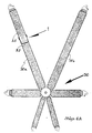
- Figure 6A illustrates a perspective view of the energy absorption and anti-submerging element shown in Figures 2, 5A of the second preferred application of the invention, before its action, born at a suitable point of the right shoulder strap of a safety belt of six hooking points fixed onto a race car's and/or aircraft's frame.
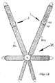
- Figure 6B illustrates a perspective view of the safety belt shown in Figure 6A however with the annex of an additional element pertaining to the second preferred application of the invention before its action that is born at a suitable point of the left shoulder belt, and with evident differentiation as this regards its smaller operational length in relation to the other element.
- Figure 7 illustrates a perspective view of the mobile buckle component that is connected to the energy absorption elements of the invention as well as the fastening system of the safety belt's shoulder strap shown in Figures 1, 2 with respect to the first and second preferred applications of the invention respectively.
- Figure 8 illustrates a perspective view of the mobile buckle component shown in Figure 3 that is connected to the energy absorption element of the invention as well as the terminal fastening component of the safety belt's shoulder strap pertaining to the third preferred application of the invention.
- Figure 9 illustrates a perspective view of the fixed hook component with lock, shown in Figure 3, that is connected to the end of the energy absorption element of the invention with regard to the third preferred application of the invention.
- Figure 10A illustrates a perspective view of the energy absorption and anti-submerging element pertaining to the first preferred application of the invention, shown in Figure 1, before its action.
- Figure 10B illustrates a side view of the element shown in Figure 10A before its action.
- Figure 11A illustrates a perspective view of the element shown in Figure 10A after its action.
- Figure 11B illustrates a side view the element shown in Figure 11A after its action.
- Figure 12A illustrates a perspective view of part of the safety belt's shoulder strap that is connected to the first energy absorption element of the invention proposed, as shown in Figs. 1, 10A, case in which the element's connection is implemented onto the shoulder strap that surrounds the element before its action.
- Figure 12B illustrates a side view of the shoulder strap shown in Figure 12A that surrounds the element before its action.
- Figure 13 A illustrates a perspective view of the shoulder strap shown in Figure 12A with its attached element after its action.
- Figure 13B illustrates a side view of the shoulder belt shown in Figure 13A with its attached element, after its action.
- Figure 14A illustrates a perspective view of part of the right shoulder strap, according to the second preferred application of the invention shown in Figs. 2, 6A, with the energy absorption element manufactured of part of the same shoulder belt as well as the insertion and connection of the mobile buckle component shown in Figure 7, but before the element's action.
- Figure 14B shows a side view of the right shoulder strap shown in Figure 14A regarding the safety belt shown in Figure 6A, together with the energy absorption and anti-submerging element that is born on the strap before its action.
- Figure 15A illustrates a perspective view of part of the right shoulder strap of the safety belt shown in Figs. 14A, 14B, however after the element's action, whereas this element operates just as the element of the first application.
- Figure 15B illustrates a side view of part of the right shoulder strap shown in Figure 15A with its attached element after its action.
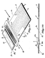
- Figure 16A illustrates a perspective view of the independent energy absorption and anti-submerging element of the third preferred application of the invention shown in Figure 3 before the element's action.
- Figure 16B illustrates a side view of the independent element shown in Figure 16A before its action.
- Figure 17A illustrates a perspective view of the independent element shown in Figure 16A after its action.
- Figure 17B illustrates a side view of the independent element shown in Figure 17A after its action.
- Figure 18A illustrates a dynamic diagram of the force exerted, in case of collision, onto the right and left shoulder straps of a safety belt by the under inertia moving to the front fastened driver, pilot etc. when the energy absorption and anti-submerging element attached to the shoulder strap is not used (discontinuous lines) as well as when the energy absorption and anti-submerging element attached to the right shoulder strap of the safety belt shown in Figure 6A is used (continuous lines).
- the figures 18B, 18C illustrate an elevation of the energy absorption and anti-submerging element of the second preferred application of the invention, that is born onto the safety strap's right shoulder belt, before and after its action, in conjunction with the temporal points specified in the diagram shown in Figure 18A.
- Figure 19A illustrates a dynamic diagram of the force that, in case of collision, is exerted onto the right and left shoulder belt of a safety belt when an attached to the two shoulder belts energy absorption and anti-immersing element is not used (discontinuous lines).
- Figure 19B illustrates a dynamic diagram of the force exerted, in case of collision, is exerted onto the right and left shoulder straps of the safety belt shown in Figure 6B when an attached to both two shoulder straps energy absorption and anti-submerging element is used (continuous lines) pertaining to the second preferred application of the invention.
- the energy absorption and anti-submerging element 1 of the invention according to the first preferred application of the invention shown in Figs. 1, 10A, 10B, 11A, 11B, 12A, 12B, 13A and 13B, the second preferred application of the invention shown in Figs. 2, 5A, 5B, 6A, 6B, 14A, 14B, 15A and 15B, and the third preferred application of the invention shown in Figs. 3, 16A, 16B, 17A and 17B, is a rectangular component with its parallel edges 1a, 1b, both of equal length, having a greater length in relation to the other parallel edges 1c and 1d, also both of equal length.
- the length of element 1 is considered to be the length of sides 1a, 1b and the width of the element 1 is considered to be the length of the sides 1c, 1d.
- the element 1 is shown to have greater volume close to edge 1d due to the configuration at this region as this regards the attachment of the load transfer component 10 to the element 1 with respect to forces exerted to the safety fastening system such as the shoulder straps of safety belts with two, three, four, five, six or more hooking points fixed onto the frame of motor vehicles and/or aircrafts.
- the fixed hook component is additionally attached with which the element 1 is firmly fixed onto the motor vehicle's and/or aircraft's frame.
- the element 1 shows, close to edge 1d, the opening 6 at its transverse length, from which the arm 10a of the mobile component 10 protrudes that transfers to the element 1 the force suddenly exerted to the fastening system of the shoulder straps of the safety belt.
- the arm 10a of the third preferred application bears medially a hole 10c.
- the element 1 is connected by means of the arm 10a of the mobile component 10 shown in Figure 7 with regard to the first and second application of the invention, as well as through the hole 10c of the arm 10a of the mobile component 10 shown in Figure 8 with regard to the third application of the invention, to the fastening system of shoulder straps of safety belts or the safety system that each time is employed.
- Element 1 bears, close to edge 1d, a suitable point 5e with which the element 1 is connected to a fixed point of the shoulder strap concerning the first and second application of the invention whereas in the third application the point 5e is connected with the fixed hook component 45.
- Element 1 includes on one hand the properly fashioned weft-knitted body made of the strap itself and on the other the suitably adapted to it mobile component 10 that transfers the load to the body of element 1 from the existing fastening system of shoulder straps of the safety belt, case in which when a force exerted to the mobile component 10 exceeds a predefined value the latter is moving lengthwise the strap's predefined transverse deformation seams or any other suitable weft-knitted material so that the energy of the suddenly exerted force is absorbed during the deformation of the element 1.
- the element 1 operates with linear cutting-off of medially transverse seams made of yarn stitches of the adjoined parts of the strap or any other suitable weft-knitted material or other composition of resistant material that are appropriate for being stitched with any kind of resistant yarn.
- the length of the suitable belt used is approximately the double of the length of the element 1, being offered as an end product so that the possibility of the strap's folding at the ends of edge 1c is afforded.
- a desirable number of transverse seams of yarn stitches 8 is provided extending lengthwise above and below the folded strap's main surface that are stitching in a predefined manner the adjoining sides of the belt.
- the transverse seams extend from the upper terminal points 6a where the cutting off commences until lower down to the folding ends of the strap, close to edge 1c, where the cutting off is terminated.
- edge 1d of the element 1 the free ends of the strap form the opening 6 where the arm 10a of the mobile load transfer component 10 is inserted and then the ends are strongly stitched together.
- the independent mobile load transfer component regarding the force exerted onto the strap of the fastening system comprises of a uniform plate 10, of which a first segment is defined at its transverse length by means of the arm 10a extending almost in parallel to the strap's main surface, and a second segment defined by means of the arm 10b connecting the mobile component 10 into the opening 6.
- the opening 9 is born with its width corresponding approximately to the width of the cut-off strap that passes though the above opening before the folding and stitching of the ends at the point 5e when the component 10 cannot exit anymore and is, consequently, trapped into the opening 6, being constrained by the transversely extended arm 10b, which extends during the entire width of the cut-off energy absorption and anti-immersing element made of strap during the element's action.
- the proposed in the present invention energy absorption and anti-submerging medium is a system composed of two and three elements that consists on one hand of the strap itself and the mobile component 10, as this regards the first and the second application of the invention shown in Figures 1,2, and, on the other, of the strap itself, the mobile component 10 as well as the fixed hook component 45 with respect to the third application of the invention shown in Figure 3.
- the length of the shoulder strap that is folded and stitched is the same with that of a strap being available in the market (i.e. 8.5 cm) manufactured so as to be cut off in a predefined manner by the same force while providing the same energy absorption and then, as shown in Figure 5B, the shoulder strap is extended during collision at the same length (i.e. 8.5 cm) after the element's action and the cutting off of the seams in a predefined manner.
- the energy absorption and anti-submerging element bearing a capable of being cut off strap by means of transverse seams
- additional advantages are achieved such as the smoothing out of the strap's cutting off process by reason of the linear and parallel to the strap's main surface shifting of the mobile component 10 transferring the load to the element 1, the linear shifting of the point of application of the force exerted during the strap's cutting off process and, subsequently, the progressive simultaneous deformation of the cut off strap as well as the force distribution lengthwise the arm 10b and, as matter of fact, widthwise the strap's seams 8 that are being cut off during the entire cutting off process.
- the independent load transfer component 10 of the element 1 offers the possibility of incomparably more precise and convenient designing of the entire energy absorption and anti-submerging element for shoulder strap fastening systems of safety belts seeing that its behaviour is accurately predictable in action.
- the elements 1 providing energy absorption and anti- submerging of the invention depending on the nominal value of the energy that are called to absorb in each case are manufactured by means of a proper planning of their parameters that may primarily consist in the number of the transverse seams of yarn stitches lengthwise the strap's cutting off in conjunction with the resistance of the stitching yarn.
- the total length of the element that determines the active length of the linear shifting of the arm lOb lengthwise the strap consists, in every case alike, a factor that specifies the nominal value of the energy absorbed.
- the changing of the defined as above variable parameters is proposed in such a manner as to afford the change of the resistance exercised lengthwise the element 1 during its cutting off and deformation.
- the element 1 becomes of a variable lengthwise resistance accompanied by the D1, D2 transverse seams' change of width lengthwise the element's strap.
- the energy absorption and anti-submerging element may consist of the folded strap whereas its stitching width D1 to be initially on the order of 4cm and it may then become D2 on the order of 6cm.
- the element 1 is proposed to operate with linear cutting off by means of the transverse seams 8.
- the length of strap 5 used is the double of the element 1 delivered as an end product (Fig. 1) so that the possibility for the folding of strap 5 at the ends of edge 1c is afforded.
- a desirable number of transverse seams 8 made of yarn stitches is provided that stitch in a pre-arranged manner the adjacent sides 5a, 5b, widthwise and lengthwise, above and below the main surface of the strap 5.
- the transverse seams 8 extend from the upper terminal points 6a where cutting off commences until lower below to the folded ends of the strap 5, close to edge 1c, where the cutting off is terminated.
- edge 1d of the element 1 the free ends 5c, 5d of the strap 5 form the opening 6 where the arm lOb of the mobile load transfer component 10 is inserted whereas next the ends 5c, 5d are adjoined and resistantly stitched at the points 5e by means of yarn 6b and afterwards this independent element 1 of the invention is connected at a suitable point of the shoulder strap of the safety belt.
- the element 1 is surrounded in a specific manner by part of the right shoulder strap 20 of the safety belt, and, in particular, the edge 1d of the element 1 that bears its stitched ends 5c, 5d is very resistantly stitched at the points 5e onto the part of the shoulder strap at its point 20a whereas then the free end of strap 20 encompasses the element 1 and passes through the opening 9 of the mobile component 10. Afterwards the shoulder strap 20 folds enclosing thus the arm 10a of the mobile component 10 into the opening 7 that is formed by the shoulder strap 20. The folded sides 20b, 20c of the shoulder strap 20 are very resistantly stitched at their contact points 20d.
- Figure 12B a side view of the connection of element 1 with the shoulder strap 20 is illustrated before its action.
- the mobile plate component 10 has been linearly shifted under the influence of force F and in parallel to the main surface of the element 1, and the arm 10b has cut the yarn seams 8 and terminated close to edge 1c of the element 1 resulting in the absorption of the energy derived by the suddenly exerted force during the deformation of element 1.
- the element 1 of the first application (Figs. 1, 10A, 12A) described above is connected at that height of the shoulder strap 20 allowing thus its passing above and backwards the fastened driver's shoulder etc.
- element 1 With the application of element 1 exclusively onto the right shoulder strap of the safety belt the asymmetrical extension between the two shoulder straps is achieved so as the right side of the fastened driver's etc. body trunk is projected and twisted further to the front than its other side that is retained in its place with the result that the body does not glide through the middle lap strap of the safety belt implying that the body's anti-submerging and, simultaneously, energy absorption during collision are achieved.
- element 1 onto the right shoulder strap Due to the advantageous application of element 1 onto the right shoulder strap provided its very small extension during the action of the element 1 the possibility of extending the use of element 1 onto the other, the left shoulder strap, is implied with regard to providing additional energy absorption and thus avoiding any unpleasant injuries when a collision occurs; however this is achieved by means of the element's smaller operational length so that both shoulder straps, right-left, are asymmetrically extended between them allowing for anti-submerging properties.
- the element 1 is proposed to be born by the same strap and manufactured of the safety belt's shoulder strap itself whereas the connection is made at the height 25 of the right shoulder strap 30a that passes above and backwards the fastened driver's etc. shoulder with regard to the safety belt 30 (Fig. 6A) with six hooking points adapted at a resistant point of the motor vehicle's and/or aircraft's frame whereas the same results with respect to the previous first application of the invention during the operation of the element 1 are offered.
- the free end of the right shoulder strap 30a passes though the opening 9 of the mobile component 10 and after having enclosed the arm 10b is adjoined to the surface of the strap's other end where at the point 5e the two sides are strongly stitched thus forming the opening 6 for the reception and trapping of the arm 10b of the mobile load transfer component 10 which results to the fact that the component 10 cannot exit anymore and is trapped into the opening 6, being constrained by the transversely extended arm 10b, which is extended widthwise the cut off strap 30a during the action of the energy absorption element 1 of the strap 30a.
- the shoulder strap 30a folds in the opposite direction and is directed to its connection with the other arm 10a of the mobile component 10.
- the shoulder strap 30a folds at a predefined length a-b and then is twisted to its opposite direction passing through the opening 9 of the lower side of the mobile component 10 and surrounds the arm 10a thus forming the opening 7 for the reception and trapping of the other arm 10a of the mobile component 10 after the folded, adjacent parts of the shoulder strap 30 are resistantly stitched at point 25c.
- the predefined length a-b of the folded part of the shoulder strap 30a is employed as a tolerance segment providing free movement of the mobile component 10 during its linear shifting and during the element's action whereas this tolerance length corresponds by approximation to the length a' - b' of the seams 8 of the element.
- element 1 proposed is an independent product before its connection to the end of the right shoulder strap of the safety belt operating just as the elements of Figures 1 and 2.
- the element 1 of the third application as an end product matches with and includes whatever the element 1 of the first application does (Fig. 1) it is however adapted to the end of the edge 1d in addition to the fixed hook component 45 (Fig. 9) with which the element 1 is capable of being firmly fixed onto the frame of a motor vehicle and/or aircraft, consisting of a first uniform plate 45, with regard to which a first part consisting of the arm 45a is defined, at its transverse length, and a second part comprising of the hook 45b with lock 45c is also defined.
- a first uniform plate 45 with regard to which a first part consisting of the arm 45a is defined, at its transverse length, and a second part comprising of the hook 45b with lock 45c is also defined.
- the element 1 is proposed to operate by means of a linear cutting off through the transverse seams 8.
- the length of the shoulder strap 40 used is measured to be more than the double of the length of element 1 as this is offered as an independent end product so that the possibility of folding the shoulder strap 40 at the ends of edge 1 c is afforded.
- a desirable number of transverse seams 8 of yarn stitches is provided that stitch in a predefined manner the adjacent sides 40a, 40b, widthwise and lengthwise, above and below the main surface of the strap 40.
- the transverse seams 8 extend from the upper extreme points 6a where cutting off commences until lower down at the folded ends of the strap 40, close to edge 1c, where the cutting off is terminated.
- edge 1d of the element 1 the free ends of sides 40a, 40b of the strap 40 form the opening 6 where the arm 10b of the mobile load transfer component 10 is inserted and thereafter the sides 40a and 40b are stitched at the points 5e by means of the yarn 6b.
- edge 1d passes through the opening 39, folds and encloses the arm 45a of the fixed hook component 45 whereas afterwards the end of edge 1d is adjoined and resistantly stitched at the points 5e.
- the arm 45a is trapped into the opening 16 formed and, as a result, the fixed hook component 45 cannot exit anymore being constrained by the transversely extended arm 45a extending widthwise the strap 40 that encircles it.
- the mobile load transfer component 10 has been linearly shifted under the action of force F and in parallel to the main surface of element 1 whereas its arm 10b has cut the yarn seams 8 and terminated close to edge 1c of the element 1 resulting in the absorption of the energy derived from the suddenly exerted force during the deformation of element 1.
- the element of the third application is always posteriorly connected with the each time existing system that is adapted onto the end of the shoulder strap as the existing load transfer hook is distributed in the market being hooked into the hole lOc of the arm 10a of the mobile component 10.
- the element 1 (Fig. 3) of the third preferred application of the invention is attached to the right shoulder strap whereas in addition to the left having a smaller length for the asymmetrical extension of the shoulder straps of the safety belt.
- This type of seat belt with the lap strap envelops and keep firm the pelvis of the passengers' etc. body.
- the additional attachment of the element 1 of the invention to the safety belts of aircrafts with two hooking points due to the beneficial adaptation of their small operational length during collision, the possibility of energy absorption by means of the small extension of the strap is provided and by extension the passenger's lesser projection to the front and therefore the avoiding of unpleasant consequences due to injury.
- the two shoulder straps illustrated with discontinuous lines exhibit almost the same value of force F that is exerted by the fastened driver.
- the force F exerted by both straps reaches a maximum on the order of 7000 N.
- the diagram of Figure 19B refers to the safety belt 30 shown in Figure 6B provided the adaptation of element 1 onto the right shoulder strap 30a and the left shoulder strap 30b.
- the operational length of element 1 of the left shoulder strap 30b is much smaller than the element 1 of the right shoulder strap 30a thus offering a very small extension of the left shoulder strap 30b during collision as well as much smaller energy absorption than the other element 1 of the right shoulder strap 30a.
- the absorbing capacity of this safety belt 30 is increased accompanied by a corresponding reduction of the possibilities of injury during collision also on the left side of the body trunk of the fastened motor vehicle driver etc.
- the two shoulder straps are asymmetrically extending in relation to each other, implying that the right 30a is extended much more than the left 30b thus offering anti-submerging properties for the fastened driver since the right side of his/her body trunk is twisted much more to the front and thus his/her body does not glide through the lap strap of his/her pelvis with the result that he/she is not submerged to the front and is not injured.
- the right shoulder strap 30a exhibits a greater temporal duration with regard to its extension in relation to the left shoulder strap 30b that extends within a smaller term.
- the force F exerted during collision onto the right shoulder strap 30a is reduced and becomes on the order of 3800 N whereas on the left shoulder strap 30b is reduced from its original value however now it is on the order of 5000 N.
Landscapes
- Engineering & Computer Science (AREA)
- Mechanical Engineering (AREA)
- Textile Engineering (AREA)
- Emergency Lowering Means (AREA)
- Automotive Seat Belt Assembly (AREA)
Applications Claiming Priority (2)
| Application Number | Priority Date | Filing Date | Title |
|---|---|---|---|
| GR99100246 | 1999-07-16 | ||
| GR99100246 | 1999-07-16 |
Publications (1)
| Publication Number | Publication Date |
|---|---|
| EP1069008A1 true EP1069008A1 (fr) | 2001-01-17 |
Family
ID=10943880
Family Applications (1)
| Application Number | Title | Priority Date | Filing Date |
|---|---|---|---|
| EP00600008A Withdrawn EP1069008A1 (fr) | 1999-07-16 | 2000-07-06 | Elément d'absorption d'énergie pour ceintures de sécurité |
Country Status (3)
| Country | Link |
|---|---|
| EP (1) | EP1069008A1 (fr) |
| GB (1) | GB0002611D0 (fr) |
| GR (1) | GR1003447B (fr) |
Cited By (11)
| Publication number | Priority date | Publication date | Assignee | Title |
|---|---|---|---|---|
| GB2402370A (en) * | 2003-06-04 | 2004-12-08 | Breed Automotive Tech | Buckle head and strap arrangement |
| GB2435916A (en) * | 2006-03-10 | 2007-09-12 | Nicholas Edward Teesdale | A sling which absorbs energy |
| US7665575B2 (en) | 2004-03-01 | 2010-02-23 | Ykk Corporation Of America | Shock absorbing fabric structures |
| US7726350B2 (en) | 2005-08-16 | 2010-06-01 | Ykk Corporation Of America | Energy absorbing webbings |
| US8316988B2 (en) | 2010-08-12 | 2012-11-27 | Ykk Corporation Of America | Shock absorbing fabric structures |
| US8387750B2 (en) | 2004-03-01 | 2013-03-05 | Ykk Corporation Of America | Shock absorbing fabric structures |
| US9328436B2 (en) | 2013-03-14 | 2016-05-03 | Ykk Corporation Of America | Energy absorbing fabric and method of manufacturing same |
| GR20150100497A (el) * | 2015-11-13 | 2017-08-04 | Παυλος Δημητριου Γιαννακοπουλος | Στοιχειο απορροφησεως ενεργειας για την εξομαλυνση της πτωσης εργαζομενου |
| US9884608B1 (en) | 2016-07-20 | 2018-02-06 | Ford Global Technologies, Llc | Four and six-point seat belt systems |
| WO2020089660A1 (fr) | 2018-11-02 | 2020-05-07 | Pavlos Giannakopoulos | Dispositif d'absorption d'énergie adapté à un impact modéré d'un aéronef, uav, équipé d'un parachute |
| IT202200000785A1 (it) * | 2022-01-19 | 2023-07-19 | Ferrari Spa | Cintura di sicurezza a quattro punti e relativo veicolo stradale |
Citations (5)
| Publication number | Priority date | Publication date | Assignee | Title |
|---|---|---|---|---|
| US3074760A (en) * | 1960-09-21 | 1963-01-22 | Hardman Tool & Engineering Co | Shock absorbing coupling and safety seat belt embodying the same |
| AU517944B2 (en) * | 1977-07-25 | 1981-09-03 | Rainfords Metal Products Pty. Ltd. | Safety restraint |
| US4618026A (en) * | 1985-09-27 | 1986-10-21 | Rose Manufacturing Company | Apparatus and method for producing a counteracting force |
| US4854608A (en) | 1987-10-16 | 1989-08-08 | Carl F. Schroth Gmbh | Safety belt |
| DE9401314U1 (de) * | 1994-01-26 | 1994-04-07 | Trw Repa Gmbh, 73553 Alfdorf | Sicherheitsgurt mit Reißnaht |
-
1999
- 1999-07-16 GR GR990100246A patent/GR1003447B/el not_active IP Right Cessation
-
2000
- 2000-02-07 GB GB0002611A patent/GB0002611D0/en not_active Ceased
- 2000-07-06 EP EP00600008A patent/EP1069008A1/fr not_active Withdrawn
Patent Citations (5)
| Publication number | Priority date | Publication date | Assignee | Title |
|---|---|---|---|---|
| US3074760A (en) * | 1960-09-21 | 1963-01-22 | Hardman Tool & Engineering Co | Shock absorbing coupling and safety seat belt embodying the same |
| AU517944B2 (en) * | 1977-07-25 | 1981-09-03 | Rainfords Metal Products Pty. Ltd. | Safety restraint |
| US4618026A (en) * | 1985-09-27 | 1986-10-21 | Rose Manufacturing Company | Apparatus and method for producing a counteracting force |
| US4854608A (en) | 1987-10-16 | 1989-08-08 | Carl F. Schroth Gmbh | Safety belt |
| DE9401314U1 (de) * | 1994-01-26 | 1994-04-07 | Trw Repa Gmbh, 73553 Alfdorf | Sicherheitsgurt mit Reißnaht |
Cited By (17)
| Publication number | Priority date | Publication date | Assignee | Title |
|---|---|---|---|---|
| GB2402370A (en) * | 2003-06-04 | 2004-12-08 | Breed Automotive Tech | Buckle head and strap arrangement |
| GB2402370B (en) * | 2003-06-04 | 2005-09-07 | Breed Automotive Tech | Buckle assembly |
| US8387749B2 (en) | 2004-03-01 | 2013-03-05 | Ykk Corporation Of America | Shock absorbing fabric structures |
| US7677360B2 (en) | 2004-03-01 | 2010-03-16 | Ykk Corporation Of America | Shock absorbing fabric structures |
| US7665575B2 (en) | 2004-03-01 | 2010-02-23 | Ykk Corporation Of America | Shock absorbing fabric structures |
| US8387750B2 (en) | 2004-03-01 | 2013-03-05 | Ykk Corporation Of America | Shock absorbing fabric structures |
| US7726350B2 (en) | 2005-08-16 | 2010-06-01 | Ykk Corporation Of America | Energy absorbing webbings |
| GB2435916A (en) * | 2006-03-10 | 2007-09-12 | Nicholas Edward Teesdale | A sling which absorbs energy |
| US8567559B2 (en) | 2010-08-12 | 2013-10-29 | Ykk Corporation Of America | Shock absorbing fabric structures |
| US8316988B2 (en) | 2010-08-12 | 2012-11-27 | Ykk Corporation Of America | Shock absorbing fabric structures |
| US9328436B2 (en) | 2013-03-14 | 2016-05-03 | Ykk Corporation Of America | Energy absorbing fabric and method of manufacturing same |
| GR20150100497A (el) * | 2015-11-13 | 2017-08-04 | Παυλος Δημητριου Γιαννακοπουλος | Στοιχειο απορροφησεως ενεργειας για την εξομαλυνση της πτωσης εργαζομενου |
| US9884608B1 (en) | 2016-07-20 | 2018-02-06 | Ford Global Technologies, Llc | Four and six-point seat belt systems |
| WO2020089660A1 (fr) | 2018-11-02 | 2020-05-07 | Pavlos Giannakopoulos | Dispositif d'absorption d'énergie adapté à un impact modéré d'un aéronef, uav, équipé d'un parachute |
| IT202200000785A1 (it) * | 2022-01-19 | 2023-07-19 | Ferrari Spa | Cintura di sicurezza a quattro punti e relativo veicolo stradale |
| EP4215420A1 (fr) * | 2022-01-19 | 2023-07-26 | FERRARI S.p.A. | Ceinture de sécurité à quatre points et véhicule routier associé |
| US11958434B2 (en) | 2022-01-19 | 2024-04-16 | Ferrari S.P.A. | Four-point seat belt and relative road vehicle |
Also Published As
| Publication number | Publication date |
|---|---|
| GR1003447B (el) | 2000-10-05 |
| GB0002611D0 (en) | 2000-03-29 |
Similar Documents
| Publication | Publication Date | Title |
|---|---|---|
| EP1069008A1 (fr) | Elément d'absorption d'énergie pour ceintures de sécurité | |
| EP0501623B1 (fr) | Amortisseur pour ceintures de sécurité de véhicules | |
| US5183007A (en) | Motorcycle safety harness | |
| DE10114343B4 (de) | Hosenträgergurt | |
| US3487474A (en) | Belt with hand-grips | |
| EP0842811A2 (fr) | Ensemble de siège de sécurité pour enfants. | |
| EP3551506B1 (fr) | Harnais de retenue supplémentaire | |
| EP0128662A2 (fr) | Ceinture de sécurité | |
| WO2002085145A3 (fr) | Dispositif de retenue de la tete / du casque d'un pilote de course | |
| EP1462363A1 (fr) | Système de positionnement pour les ceintures thoraciques d'un système de ceinture de sécurité dans la direction longitudinale des branches d'un joug | |
| US5524928A (en) | Automobile restraint system | |
| US5088161A (en) | Seat belt safety clip | |
| US20020107119A1 (en) | Abdominal exercise apparatus | |
| US20140305384A1 (en) | Vehicular dog restraint | |
| US11958434B2 (en) | Four-point seat belt and relative road vehicle | |
| DE2416313C3 (de) | Sicherheitseinrichtung für die Insassen von Fahrzeugen, insbesondere Kraftfahrzeugen | |
| US2833555A (en) | Vehicle safety belt | |
| US5997097A (en) | Restraining device | |
| WO1992002389A1 (fr) | Ameliorations relatives aux ceintures de securite d'un vehicule | |
| EP1262383B1 (fr) | Connecteur pour siège de sécurité pour enfants | |
| US7128374B2 (en) | Energy absorbing device with torso displacement limiter | |
| US3125376A (en) | Safety belt | |
| KR102381749B1 (ko) | 벨트가이드장치 및 이를 갖춘 안전벨트장치 | |
| US20050044671A1 (en) | Safety belt web adjuster | |
| CA2141779C (fr) | Nouvelle configuration de ceinture de securite |
Legal Events
| Date | Code | Title | Description |
|---|---|---|---|
| PUAI | Public reference made under article 153(3) epc to a published international application that has entered the european phase |
Free format text: ORIGINAL CODE: 0009012 |
|
| AK | Designated contracting states |
Kind code of ref document: A1 Designated state(s): DE ES FR GB IT SE |
|
| AX | Request for extension of the european patent |
Free format text: AL;LT;LV;MK;RO;SI |
|
| 17P | Request for examination filed |
Effective date: 20010618 |
|
| AKX | Designation fees paid |
Free format text: DE ES FR GB IT SE |
|
| 17Q | First examination report despatched |
Effective date: 20030904 |
|
| STAA | Information on the status of an ep patent application or granted ep patent |
Free format text: STATUS: THE APPLICATION IS DEEMED TO BE WITHDRAWN |
|
| 18D | Application deemed to be withdrawn |
Effective date: 20060201 |