EP1069007B1 - Occupant protection device of vehicle - Google Patents
Occupant protection device of vehicle Download PDFInfo
- Publication number
- EP1069007B1 EP1069007B1 EP00114040A EP00114040A EP1069007B1 EP 1069007 B1 EP1069007 B1 EP 1069007B1 EP 00114040 A EP00114040 A EP 00114040A EP 00114040 A EP00114040 A EP 00114040A EP 1069007 B1 EP1069007 B1 EP 1069007B1
- Authority
- EP
- European Patent Office
- Prior art keywords
- airbag
- vehicle
- pillar
- expanded
- occupant
- Prior art date
- Legal status (The legal status is an assumption and is not a legal conclusion. Google has not performed a legal analysis and makes no representation as to the accuracy of the status listed.)
- Expired - Lifetime
Links
- 238000004826 seaming Methods 0.000 description 11
- 238000009958 sewing Methods 0.000 description 8
- 239000005357 flat glass Substances 0.000 description 6
- 238000004519 manufacturing process Methods 0.000 description 3
- 230000006866 deterioration Effects 0.000 description 2
- 239000002360 explosive Substances 0.000 description 2
- 238000007789 sealing Methods 0.000 description 2
- 238000004904 shortening Methods 0.000 description 2
- 238000003466 welding Methods 0.000 description 2
- 229910000831 Steel Inorganic materials 0.000 description 1
- 238000005452 bending Methods 0.000 description 1
- 238000006243 chemical reaction Methods 0.000 description 1
- 238000004891 communication Methods 0.000 description 1
- 238000006073 displacement reaction Methods 0.000 description 1
- 238000009826 distribution Methods 0.000 description 1
- 230000000694 effects Effects 0.000 description 1
- 208000037805 labour Diseases 0.000 description 1
- 238000000034 method Methods 0.000 description 1
- 230000000149 penetrating effect Effects 0.000 description 1
- 239000011347 resin Substances 0.000 description 1
- 229920005989 resin Polymers 0.000 description 1
- 239000000565 sealant Substances 0.000 description 1
- 230000035939 shock Effects 0.000 description 1
- 239000010959 steel Substances 0.000 description 1
Images


Classifications
-
- B—PERFORMING OPERATIONS; TRANSPORTING
- B60—VEHICLES IN GENERAL
- B60R—VEHICLES, VEHICLE FITTINGS, OR VEHICLE PARTS, NOT OTHERWISE PROVIDED FOR
- B60R21/00—Arrangements or fittings on vehicles for protecting or preventing injuries to occupants or pedestrians in case of accidents or other traffic risks
- B60R21/02—Occupant safety arrangements or fittings, e.g. crash pads
- B60R21/16—Inflatable occupant restraints or confinements designed to inflate upon impact or impending impact, e.g. air bags
- B60R21/23—Inflatable members
- B60R21/231—Inflatable members characterised by their shape, construction or spatial configuration
- B60R21/2334—Expansion control features
- B60R21/2338—Tethers
-
- B—PERFORMING OPERATIONS; TRANSPORTING
- B60—VEHICLES IN GENERAL
- B60R—VEHICLES, VEHICLE FITTINGS, OR VEHICLE PARTS, NOT OTHERWISE PROVIDED FOR
- B60R21/00—Arrangements or fittings on vehicles for protecting or preventing injuries to occupants or pedestrians in case of accidents or other traffic risks
- B60R21/02—Occupant safety arrangements or fittings, e.g. crash pads
- B60R21/16—Inflatable occupant restraints or confinements designed to inflate upon impact or impending impact, e.g. air bags
- B60R21/23—Inflatable members
- B60R21/231—Inflatable members characterised by their shape, construction or spatial configuration
- B60R21/232—Curtain-type airbags deploying mainly in a vertical direction from their top edge
-
- B—PERFORMING OPERATIONS; TRANSPORTING
- B60—VEHICLES IN GENERAL
- B60R—VEHICLES, VEHICLE FITTINGS, OR VEHICLE PARTS, NOT OTHERWISE PROVIDED FOR
- B60R21/00—Arrangements or fittings on vehicles for protecting or preventing injuries to occupants or pedestrians in case of accidents or other traffic risks
- B60R21/02—Occupant safety arrangements or fittings, e.g. crash pads
- B60R21/16—Inflatable occupant restraints or confinements designed to inflate upon impact or impending impact, e.g. air bags
- B60R21/23—Inflatable members
- B60R21/231—Inflatable members characterised by their shape, construction or spatial configuration
- B60R21/2334—Expansion control features
- B60R21/2338—Tethers
- B60R2021/23386—External tether means
Definitions
- an occupant protecting device of a vehicle including an air bag which is guided by a guiding element along a guiding rod which is attached to a C-pillar of the vehicle. At the lower end of the guiding rod a means for locking the guiding element is provided.
- the front tether 18 is disposed along the front pillar 2, while, in the expanded condition of the airbag 10, the front tether is rotated around the bolt 22 due to the downward extension of the lower end of the airbag 10.
- a condition in which the front tether is longitudinally extended as shown in Figs. 1 and 8 is created.
- reference numeral 1 generally designates a body of the vehicle in which a compartment 1a of the vehicle is formed therein.
- the body comprises a front pillar 2 inclined rearward, a center pillar 3 extended vertically, a rear pillar 4 inclined frontward, a roof connected to each upper end of pillars 2 to 4 and a floor by a roof rail 5.
- a front window glass 25 is fit in a front window 7 which employs the front pillar 2 and a front-half of the roof as a part of a window frame.
- a rear window glass is fit in a rear window 71 which employs the rear pillar 4 and a rear-half of the roof as a part of a window frame.
- a front door 85 is fit in an front opening 84 defined by the front pillar 2, the center pillar 3, the roof and the floor so as to be opened and dosed.
- a rear door 89 is fit in a rear opening 88 defined with the center pillar 3, the rear pillar 4, the roof and the floor so as to be opened and closed.
- a window 86, 90 is formed on an upper portion of the door 85, 89 in which a window glass 97, 91 is opened and closed (a rear-half portion of the window 90 of the rear door 89 is a fixed sash window where the window glass 91 cannot be opened).
- a predetermined width of space is provided between the inner panel 74, which is of the front pillar 2, the rear pillar 4 and the roof rail 5, and each of the trims 95, 97, 98, i.e. each interior of the trims 95, 97, 98.
- an airbag 10 which is expanded when an impact load is acted on the side of the vehicle body 1 is folded and housed.
- the airbag 10 is housed within the range from the upper end of the front pillar 2 through the roof rail 5 to the upper end of the rear pillar 4 along therewith (see Fig. 7).
- a gas supply pipe 45 is inserted into and through an upper end of the airbag 10 to continuously extending throughout the airbag 10.
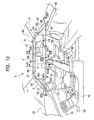
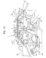
- a plurality of discharge ports 46, 46..., 46 are formed on and along the gas supply pipe 45 (the plurality of discharge ports 46, 46..., 46 are represented by dots in Fig. 13 to show only their positions).
- three discharge ports 46, 46, 46 which are dispersed with approximately uniform interval are formed in a portion disposed on the roof rail 5 above the front door 85.
- Other three discharge ports 46, 46, 46 are also formed in a portion disposed between the roof rail 5 above the rear door 89 and a portion above the rear pillar 4.
- a gas generated by the actuation of the inflator 49 is introduced into the airbag 10 through the gas supply pipe 45 and the discharge ports 46, 46..., 46 of the gas supply pipe to expand the airbag 10.
- the airbag 10 is expanded separately into the first expansion area 42 covering most area and the second expansion area 43 covering rear end area.
- the first expansion area 42 is expanded to cover the windows 86, 90 of the front and the rear doors 85, 89.
- each of the front and the rear connecting members 51, 54 is run out into the compartment through the opening between the edge of the pillar trim 95, 97 and the inner panel 74 respectively and is pulled by the airbag 10.
- the longitudinal tension is provided to the lower portion of the airbag 10 by the connecting members 51 and 54. This makes it possible to absorb the impact generated by the secondary collision of the occupants P1, P2 toward the window glasses 87, 91 and to prevent the occupants P1, P2 from being thrown out of the windows 86, 90.
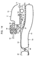
- a rear end portion of the first expansion area 42 and the second expansion area 43 of the airbag 10 and the rear connecting member 54 are housed in the pillar trim 97 covering the rear pillar 4 in the vehicle compartment, and are run out the front end of the rear pillar trim 97 to be expanded into the compartment.
- both of the rear end portion of the first expansion area 42 of the airbag 10 to be expanded in a front side of the front end of the rear pillar trim 97 and the second expansion area 43 to be expanded in a rear side of the front end of the rear pillar trim 97 can be housed to be hidden from the inside of the vehicle compartment, and thereby the airbag 10 can be housed while keeping good appearance.
- the present invention is not limited to the vehicle of the above embodiment having two doors 85, 86 on a side of the vehicle body 1, but may be applied to any type of vehicle having a rear pillar in a rear side of the window including a vehicle having one door in a side thereof.
Landscapes
- Engineering & Computer Science (AREA)
- Mechanical Engineering (AREA)
- Air Bags (AREA)
Description
- The present invention relates to an occupant protection device, such as an airbag, for protecting an occupant when an impact load is acted on a vehicle, and, in particular, to one type of airbag which is expanded along a side window to protect an occupant's head and to prevent the occupant from being thrown out of a compartment of the vehicle.
- Heretofore, as to such a occupant protection device of a vehicle, there. has been known a device, for example, disclosed in Japanese Patent Laid-open Publication No. Hei 10-166988, in which a longitudinally extendable airbag is folded and the folded airbag is housed along a front pillar and a roof side frame to be expanded downward along a side window in the form of a curtain when an impact load is acted on a side of a vehicle.
- In the device described above, a front end of the airbag is connected to a lower side of the front pillar of the vehicle, while its rear end is connected to an upper side of a quarter pillar. The airbag is also divided over the front end to the rear end into a plurality of small bags (expanding portions) which may extend approximately vertically with having respective cylinder shapes, i.e. a curtain-like shape as a whole, in the expanded condition of the air bag. Expanding these plurality of small bags respectively makes the airbag shorten in the longitudinal length as a whole. This results in a tension in the longitudinal direction to enable the airbag to restrain a head or the like of an occupant.
- Further, among the plurality of small airbags in this conventional airbag described above, the small bags disposed rearward with respect to a center pillar of the vehicle are adapted to have particularly large size in diameter than others. This may improve the restraint performance to an occupant because, for example, when an occupant's head which is moving toward outside of the compartment is restrained by the airbag, the small bags having larger diameter may be caught by the center pillar to control a displacement of the airbag.
- However, since the conventional airbag is made by sewing to divide it into the plurality of small bags, there is a problem that a shock absorbing performance cannot sufficiently be obtained in the vicinity of seams of the airbag and an overall occupant protection performance is also lowered. In addition, since a strength of the airbag is lowered in proportion to increased seams, there is the possibility that the seams is tom during its expansion, resulting in deterioration of the occupant protection performance.
- Further, in addition to a sewing operation for making such an airbag, it is also necessary to apply an sealant to the seams for preventing a expansion gas from leaking through the seams. This additional measure requires significant labors and times, and results in remarkably increased manufacturing cost.
- From EP-A1-0 955 213 (document falling under Art. 54(3) EPC) an occupant protecting device of a vehicle is known, including an air bag which is guided by a guiding element along a guiding rod which is attached to a C-pillar of the vehicle. At the lower end of the guiding rod a means for locking the guiding element is provided.
- From DE-U1-298 06 200 (corresponding to the preamble of claim 1) an inflatable gas bag is known, which is guided along a roof side rail by means of a piston which is located in a gas distribution hose.
- From GB-A-2 324 068 (corresponding to the preamble of claim 1) a side impact airbag tensioned by an inflatable shortening strap is known. The shortening strap may comprise inflatable pockets causing the strap walls to bulge, a single inflatable cell shortened by the orientation of a weave or may be a length of webbing meandering between inflatable cylindrical cells.
- From EP-A1-0 814 001 an airbag device is known, at which the gas cushion is stretched between a front and a rear fixing point located a the lower end of an A- and a C-pillar, respectively.
- From DE-A1-197 04 051 a protection device including a side impact airbag is known, at which the airbag is stretched by a pulling or tightening cord.
- From DE-U1-298 03 985 U1 an airbag module is known, at which the air bag is stretched by a guy rod or band.
- It is the object of the invention to enhance the occupant protection performance and the cost reduction through means of reducing seams of an airbag with maintaining the occupant restraint performance by exercising ingenuity in a structure for giving a tension in the longitudinal direction to the airbag during its expansion, in a certain type airbag expanding to cover an inside of a side window when an impact is acted on a vehicle. Furthermore, it is an object to improve the curtain airbag type of occupant protection device of introducing a new layout in anexpansion of the airbag so that the impact load at the time when the occupant secondarily collides with the rear pillar disposed on the rear side of the window can be absorbed to securely protect the occupant.
- This object is fulfilled by an occupant protection device of a vehicle having the features disclosed in claim 1.
- To achieve the aforementioned object, the present invention provides connecting members for connecting front and rear ends which are located at a lower portion of an airbag to a body of a vehicle body respectively, and a slack absorbing device applied to at least one of the connecting members for absorbing a slack of the connecting members in the expanded condition of the airbag.
- In particular, according to the present invention, there is provided an occupant restraint equipment of a vehicle on the presumption that the vehicle includes a front side pillar and a rear side pillar disposed on front and rear sides of a side window of the vehicle respectively, and a roof side rail longitudinally extended to connect respective upper ends of the both pillars each other, and the occupant protection device includes an airbag which is folded and housed in the range from the front side pillar to the rear side pillar through the roof side rail so that the airbag is expanded to cover an inside of the side window when an impact load is acted on a side of the vehicle. Thereat, the occupant restraint equipment of the present invention comprises an upper edge of the airbag fixed to at least the roof side rail, a front connecting member for connecting a front lower end of the airbag to a body of the vehicle positioned frontward more than the side window, a rear connecting member for connecting a rear lower end of the airbag to a body of the vehide positioned rearward more than the side window; and a slack absorbing device attached to at least one of the front and rear connecting members for absorbing a slack in the connecting members in the expanded condition of the airbag.
- According to the aforementioned structure, the airbag primarily housed.in the roof side rail of the vehicle is extended downward to cover the inside of the side window when an impact load is acted on the side of the vehicle. On this way, the folded airbag is extended downward as a whole, and a slack of the connecting members fixed to the lower side of the airbag is absorbed by the slack absorbing device, so that the front and rear connecting members may provide a sufficient tension to the air bag by longitudinal pulling of the connecting members. Thus, it is no longer required to divide the air bag into a plurality of small bags as the conventional airbag. This enables to decrease the seams of the airbag to which an occupant would be contacted in the expanded condition of the airbag, and so the occupant protection performance can be improved. In addition, the manufacturing cost can be reduced due to the reduced seams.
- According to the present invention, the slack absorbing device may be disposed between at least one of the connecting members and a body of the vehicle. In this embodiment, it is unnecessary to process the airbag for providing the slack absorbing device. Thus, the increased seams and complicated structure of the airbag caused from this processing can be avoided. As a result, possible deterioration of the occupant protection performance and increased cost of the airbag can be prevented.
- At least one of the connecting members includes a first end connected to the airbag and a second end connected to the body, the first end being disposed upward more than the second end in the housed condition of the airbag, and the slack absorbing device includes a guide member for guiding the at least one of the connecting members with making the at least one of the connecting members bend when the first end is moved downward in the expanded condition of the airbag.
- Without the slack absorbing device, since the first end of the connecting member is located upward more than the second end of the connecting member when the airbag is housed and is moved downward in the expanded condition of the airbag, a distance between both the ends of the connecting member in the expansion of the airbag becomes shorter than that in the housed condition of the airbag, and this causes a slack of the connecting members. In this embodiment of invention, since the connecting member is guided by the guide member to make the connecting member bend when the first end of the connecting member is moved downward in the expanded condition of the airbag, the slack of the connecting member can be absorbed.
- The guide member includes a bank portion for pushing the at least one of the connecting members in the inward direction with respect to a compartment of the vehicle in the expanded condition of the airbag. This causes the connecting members to be pushed and bent by the bank portion in the middle of the expansion of the airbag. Thus a slack of the connecting members can be absorbed. In addition, since the airbag is wholly pushed in the inward direction with respect to a compartment through the connecting members, the occupant restraint performance can be enhanced.
-
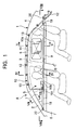
- Fig. 1 shows an structure of a curtain type airbag device in the expanded condition of an airbag in order to explain the present invention,
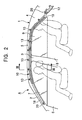
- Fig. 2 is a view equivalent to Fig. 1 in the housed condition of an airbag,
- Fig. 3 is a cross sectional view taken from the plane of the line III-III in Fig. 2 showing a structure for fixing an airbag to a roof side rail,
- Fig. 4 is a cross sectional view taken from the plane of the line IV-IV in Fig. 1,
- Fig. 5 is a cross sectional view taken from the plane of the line V-V in Fig. 1,
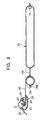
- Fig. 6 is a partial enlarged view showing a structure where a front tether is attached to a front pillar,
- Fig. 7 is a cross sectional view taken from the plane of the line VII-VII in Fig. 1,
- Fig. 8 is a cross sectional view taken from the plane of the line VIII-VIII in Fig. 1,
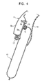
- Fg. 9 is a view equivalent to Fig. 1 according to another airbag device in order to explain the present invention,
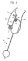
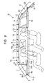
- Fig. 10 is a perspective view showing an arrangement where a rear tether is housed in a rear pillar of a vehicle in the housed condition of an airbag,
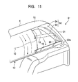
- Fig. 11 is a view equivalent to Fig. 10 showing the expanded condition of an airbag according to the present invention.
- Fig. 12 is an elevational view showing an airbag of an occupant protection device in order to explain the present invention, illustrating in an expanded condition of the air bag viewed from an inside of a compartment of a vehicle,
- Fig. 13 is an elevational view similar to Fig. 12 illustrating in a housed condition of the airbag of the occupant protection device,
- Fig. 14 is a cross sectional enlarged view taken from the plane of the line XIV-XIV in Fig. 12,
- Fig. 15 is a cross sectional enlarged view taken from the plane of the line XV-XV in Fig. 13,
- Fig. 16 is a cross sectional enlarged view taken from the plane of the line XVI-XVI in Fig. 13,
- Fig. 17 is a cross sectional enlarged view taken from the plane of the line XVII-XVII in Fig. 12,
- Fig. 18 is a cross sectional enlarged view taken from the plane of the line XVIII-XVIII in Fig. 13,
- Fig. 19 is a cross sectional enlarged view taken from the plane of the line XIX-XIV in Fig. 12, and
- Fig. 20 is a cross sectional enlarged view taken from the plane of the line XX-XX in Fig. 12.
-
- With reference to the drawings, a preferred embodiment of the present invention will be described hereinafter.
- Fig. 1 shows a curtain type airbag device A ( an occupant protection device of a vehicle) in order to explain the present invention. The curtain type airbag device A is mounted on a right side body of three box type of a passenger vehicle 1. As shown, the airbag device is expanded to protect occupants when an impact which is higher than a predetermined value is acted on a right side of the vehicle 1load. The curtain type airbag device A is also mounted on a left side body of the vehicle, but not shown.
- In the right side body of the vehicle 1, a
front pillar 2 connected to an engine-hood(not shown), acenter pillar 3 and aquarter pillar 4 are disposed in the order from a front side of the body (i.e. the left side in the drawing). Aroof side rail 5 longitudinally extends to connect thefront pillar 2, thecenter pillar 3 and thequarter pillar 4 at their upper ends each other. A front door 6 and afront side window 7 are disposed between thefront pillar 2 and thecenter pillar 3, while a rear door 8 and arear side window 9 are disposed between thecenter pillar 3 and thequarter pillar 4. - As shown in Fig. 2, an
airbag 10 is folded and housed in the range from a front end of theroof side rail 5 to thequarter pillar 4. Anairbag 10 is made by sewing two sheets each other around their peripheries to form into a large bag. In a side view in the expanded condition of theairbag 10 as shown in Fig.1, the airbag has a shape extending longitudinally. A front edge of the airbag approximately straightly extends in the vertically direction, while a rear edge of the airbag is formed in a slant portion which extends more rearward as going downward. An opening is formed in a lower end of the slant portion, and ahose 11 made of resin is inserted into the opening airtightly. Thehose 11 is connected to acylindrical inflator 12 housing an igniter and an explosive and is also extended through the inside of theairbag 10 along an upper periphery up to a front end of the airbag. The a plurality of gas supply ports are also provided in the middle ofhose 11 to uniformly supply a high pressure gas from the inflator 12 into theairbag 10 through the gas supply ports.. - Six fixing
brackets airbag 10 from the front end to rear end of the air bag with uniformly spacing apart respectively. As shown in detail in Fig. 3, each of the fixingbrackets 13 is formed, for example, by bending a steel sheet to clamp the upper periphery of theairbag 10 and thehose 11, and is also fastened to aninner panel 5a of theroof side rail 5 by abolt 14. - That is, the
airbag 10 is fixed to theroof side rail 5 at the upper periphery of the air bag by the fixingbracket 13 and is also housed below the fixing bracket between theroof side rail 5 and aroof trim 16 with being folded. In Fig. 3,reference numeral 17 designates a seaming welt for covering a welding flange of the roofinner panel 5a and a roofouter panel 5b. A protrudingrib 17a is formed on the seamingwelt 17 to be engaged and held with a periphery of theroof trim 16. - When the impact load is acted on the right side of the vehicle 1 and an ignition signal is then input from a sensor (not shown) to the inflator 12, the
airbag 10 is expanded by the high pressure gas supplied from the inflator 12 to push and open theroof trim 16. As shown in Figs. 4 and 5, the air bag is extended downward to restrain and protect a occupant's head and so prevent the occupant from being thrown out of the vehicle. As respectively shown in Figs.1 and 5, anon-expansive area 10a is provided by sewing right and left sheets of theairbag 10 each other at a portion positioned slightly rearward from a central portion of theairbag 10 to control an excessive expansion of both the sheets. The non-expansive area is provided so as not to contact the occupant resulting in reduction of a volume of theairbag 10, a time necessary for the expansion of the airbag, and the overall size of the device. - In general, when the
airbag 10 extended longitudinally is widely expanded in the laterally direction in its expanded condition, theairbag 10 is likely to expand toward an occupant and to come in contact the occupant. Such a negative influence can be avoided by providing thenon-expansive area 10a in theairbag 10 to properly control a lateral expansion of the airbag. -
Tethers 18 and 19 (i.e. a front and rear connecting members respectively) are attached to the front lower end and rear lower end of theairbag 10 respectively for pulling theairbag 10 in the longitudinal direction in its expanded condition. That is, one end of thefront tether 18 is attached to the front end of theairbag 10 and another end of the front tether is fixed to a lower end of thefront pillar 2. As shown in detail in Fig. 6, the end of thefront tether 18 which is located near to the pillar is fixed to abuckle 20 which is attached rotatably to abolt 22 together with acollar 21. Thus, the end is attached to an inner surface of aninner panel 2a of thefront pillar 2 by thebolt 22. As shown in Fig. 2 in the housed condition of theairbag 10, thefront tether 18 is disposed along thefront pillar 2, while, in the expanded condition of theairbag 10, the front tether is rotated around thebolt 22 due to the downward extension of the lower end of theairbag 10. As a result, a condition in which the front tether is longitudinally extended as shown in Figs. 1 and 8 is created. - One
fixing bracket 13 is disposed in the middle of the slant portion. One end of therear tether 19 which is shorter than thefront tether 18 is sewed to the rear end of theairbag 10, i.e. the proximity of the opening into which thehose 11 is inserted. Another end of therear tether 19 is rotatably attached to a lower end of thequarter pillar 4 via thebuckle 20 as same as thefront tether 18. When theairbag 10 is in its housed condition shown in Fig. 2, thefront tether 18 is housed in the pillar trim 23 as shown in Fig. 7. The fixingbracket 13 disposed in the rear end of theairbag 10 and therear tether 19 are also housed in a pillar trim. This provides good appearance and an improved the commercial value. - In Fig. 7,
reference numerals front pillar 2 having a closed section. Afront window 25 is supported by the pillarouter panel 2b via a sealingmember 24. Areference numeral 26 designates a seaming welt for covering a welding flange of the pillarinner panel 2a and the pillarouter panel 2b. A protrudingrib 26a is formed on the seamingwelt 26 for engaging with a periphery of the pillar trim 23 to hold it. - The of
airbag 10 according to the present device longitudinally extends as described above and is also not divided into a plurality of small bags as a conventional curtain type airbag, but is formed into one large bag as a whole. Accordingly, when theairbag 10 is transferred from its housed condition shown in Fig. 2 to its expanded condition shown in Fig. 1, theairbag 10 is not very reduced its length in the longitudinal direction, but is likely to generate a slack of thefront tether 18 which caused an insufficient longitudinal tension provided to theairbag 10. This might cause a fear that, when the an impact load is acted on a body of a vehicle or the vehicle is then turned over, the occupant might deform theairbag 10 outward to be thrown out of the vehicle through the side window. - Then, in the present device, an ingenious device is exercised over a connecting structure between the
front tether 18 and the front end of theairbag 10 so that a sufficient tension may be provided to theairbag 10 by absorbing the slack of thefront tether 18 in the expanded condition of the airbag. Because of the structure described above, even when the impact load is acted on the body of the vehicle or the vehicle is then turned over, the occupant can be protected so as to be secured within the compartment of the vehicle by theairbag 10 to in which the sufficient tension is provided. Thus a vehicle occupant protection performance can be improved. - As particularly shown in Figs. 1 and 8, a
hole 10b is formed on the front end of theairbag 10 with penetrating theairbag 10 laterally. The end portion of thefront tether 18 which is located near to the airbag extends with be wound around the expandingportion 10c from a front right side of an expandingportion 10c positioned frontward more than thehole 10b. Then after the end portion passes through thehole 10b and then returns back frontward at an opposite left side, the end portion is sewn together to theseam 10d of theairbag 10 with being wound around the left side of theexpansion portion 10c. That is, the expandingportion 10c which is expanded in the expanded condition of theairbag 10 is provided at the front end portion of theairbag 10, the through-hole 10b is formed in theairbag 10 rearward more than the expandingportion 10c (in the direction of central portion of the airbag 10), and the end portion of thefront tether 18 which is located near to theairbag 10 is wound approximately one circle around the expandingportion 10c and then is fixed to the front edge of theairbag 10. - According to the structure described above, when the housed
airbag 10 is expanded, the expandingportion 10c located at the front end of theairbag 10 is also expanded. As shown in Fig. 8, the end portion of thefront tether 18 is wound around the expandingportion 10c and the slack thereon is absorbed thoroughly. Accordingly, even if an amount of slack is generated on thefront tether 18, it can be absorbed completely and a sufficient tension can be provided to theairbag 10. In addition, a load provided by thefront tether 18 to theairbag 10 is dispersed over a surrounding area of the expandingportion 10c, and thereby a reliability of theairbag 10 can be improved. Thehole 10b and the expandingportion 10c of theairbag 10 and a fixing structure of the front tether to them correspond to a slack absorbing device S for absorbing the slack of thetether 18 in the expansion of theairbag 10. - Therefore, in the occupant protection device of the vehicle A, when, for example, a vehicle collides to the right side of the vehicle 1 and the impact load which is higher than a predetermined value is acted on the vehicle , the igniter of the inflator 12 is set off in response to the input from the sensor to induce a fast-bum of the explosive and a great amount of gas generated thereby is introduced into the
airbag 10 through thehose 11. Then theairbag 10 is rapidly expanded and extended downward from theroof side rail 5 to cover the inside of the front and therear side windows - At that time, the expanding
portion 10c at the front end of theairbag 10 is expanded by the high pressure gas introduced therein with having approximately cylindrical shape. At this time, the expanding portion winds up the end portion of thefront tether 18 to thoroughly absorb the slack of thetether 18, so that the sufficient level of longitudinal tension can be provided to theairbag 10. Therefore, the restraint performance for the occupant can be secured without dividing theairbag 10 into a plurality of small bags as the conventional curtain type airbag. - Further, since the
airbag 10 is not divided and thereby the seam is removed from a contact area with the occupant, the occupant protection performance of theairbag 10 can be improved as a whole. In addition, since there is no need for sewing theairbag 10 to divide it and for sealing the sewed portion, a man-hour for these operations can be saved to reduce the manufacturing cost significantly. - Since the
airbag 10 is expanded to cover both of the front and therear side windows - Further, since the periphery of the
front tether 18 is sewed to theairbag 10 using theoriginal seam 10d together, there is no fear of a strength reduction of the airbag due to an increase of the sewing portion. - Although, in the device described above, the end portion of the
tether 18 in theairbag 10 side is wound around the expandingportion 10c and the periphery of the end portion is sewed at the seams of theairbag 10 together, the sewing manner is not limited thereto. That is, the periphery of thefront tether 18 may unnecessarily be sewed to a vicinity of the seam of theairbag 10. Alternatively, for example, the end portion of thetether 18 is not wound around the expandingportion 10c, but may be simply sewed at a position which is expanded at least in the lateral direction. - Figs. 9 to 11 show a device in which a curtain type airbag device A is applied to a
wagon type vehicle 30. Since the curtain type airbag device A is similar to that of the aforementioned device in a schematic structure of theairbag 10, an attaching structure of thefront tether 18 or the like, the similar members are represented by the similar reference numerals and a description for them will be omitted. A feature of the curtain type airbag device A is that a slack absorbing device S' for absorbing a slack of therear tether 19 in the expansion of theairbag 10 is provided between therear tether 19 and arear pillar 31. - As shown in detail in Fig. 10, in the housed condition, the
airbag 10 is folded and housed between theroof side rail 5 and the roof trim 16 as same as the case of the aforementioned embodiment, and also therear tether 19 is housed between therear pillar 31 and apillar trim 32. In this condition, one end of therear tether 19 which is located near to theairbag 10 is in a higher position than the other end of the airbag which is located near to therear pillar 31. - The pillar trim 32 comprises a
front frame member 33 and arear panel member 34. Though not shown in detail, theframe member 33 is fixed to an inner panel of therear pillar 31 by a bolt and is gradually protruded into the compartment along an upper side to a lower side to form abank portion 33a at a lower end thereof with protruding toward an inside of the compartment. Further thisframe member 33 has high rigidity capable of resisting an expanding force of theair bag 10. Thepanel member 34 is engaged with a rear periphery of theframe member 33 at a front end thereof and is held so as to fit an inside of therear pillar 31. - When a high pressure gas is supplied from the inflator 12 and the
airbag 10 is expanded as shown in Fig. 11, theairbag 10 pushes and opens theroof trim 16 and extends downward into the compartment. Then, therear tether 19 attached to a lower portion of theairbag 10 also pushes open thepanel member 34 of the pillar trim 32 to move downward as shown by chain lines in the same drawing. At that time, according to the invention, since therear tether 19 always moves downward along theframe member 33, therear tether 19 is pushed toward the inside of the compartment as theairbag 10 is expanded, and is pushed by thebank portion 33a of theframe member 33 toward the inside of the compartment to be formed into approximate L-shape as shown by real lines in the same drawing when theairbag 10 is completely expanded. - Accordingly, in this device, since the
rear tether 19 is pushed out toward the inside of the compartment along theframe member 33 by a downward expanding force of theairbag 10, the slack of therear tether 19 can be absorbed and a sufficient tension is provided to the rear tether. Thus, the same operational effect with that of the aforementioned embodiment can be achieved, which allows to accomplish an improvement of the occupant protection performance as well as a cost reduction of theairbag 10, while securing a occupant restraint performance. In addition, the vehicle occupant protection device performance of theairbag 10 can be further improved by providing a force, which directs the airbag toward the inside of the compartment, to theairbag 10 via therear tether 19. - The
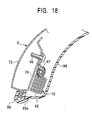
frame member 33 corresponds to a guide member for guiding therear tether 19 in the expansion of theairbag 10, and a slack absorbing device S' is configured by theframe member 33, thebank portion 33a formed on the lower end thereof and an arrangement and structure of therear tether 19. Since the slack absorbing device S' has no necessity to form the through-hole 10b on theairbag 10 as of the slack absorbing device S applied to the front end of theairbag 10, such a problem as to increase the seams in the airbag or to make the structure thereof complicated can be avoided. - Figs. 12 and 13, show an inside of a compartment of a vehicle equipped with an occupant protection device A illustrated in an expanded condition of an airbag by Fig. 12 and a housed (unexpansion) condition of the airbag by Fig. 13.
- In Figs. 12 and 13, reference numeral 1 generally designates a body of the vehicle in which a compartment 1a of the vehicle is formed therein. The body comprises a
front pillar 2 inclined rearward, acenter pillar 3 extended vertically, arear pillar 4 inclined frontward, a roof connected to each upper end ofpillars 2 to 4 and a floor by aroof rail 5. Afront window glass 25 is fit in afront window 7 which employs thefront pillar 2 and a front-half of the roof as a part of a window frame. A rear window glass is fit in arear window 71 which employs therear pillar 4 and a rear-half of the roof as a part of a window frame. -
Reference numeral 75 designates a front seat (driver's seat) installed in a front side of the compartment of the vehicle, on which a driver P1 as an occupant takes a seat.Reference numeral 77 designates a steering wheel disposed on front of thefront seat 75,reference numeral 78 designates an instrument panel disposed on a front end of the compartment of the vehicle, andreference numeral 79 designates a floor console installed on the floor next to thefront seat 75.Reference numeral 81 designates a rear seat installed in a rear portion of the vehicle compartment, on which an occupant P2 takes a seat. - In a left and right sides (the right side is shown in the drawing) of the vehicle body 1, a
front door 85 is fit in anfront opening 84 defined by thefront pillar 2, thecenter pillar 3, the roof and the floor so as to be opened and dosed. Arear door 89 is fit in arear opening 88 defined with thecenter pillar 3, therear pillar 4, the roof and the floor so as to be opened and closed. Awindow door window glass window 90 of therear door 89 is a fixed sash window where thewindow glass 91 cannot be opened). Thus, thefront pillar 2 is disposed on a front side of thewindow 86 of thefront door 85 extending approximately vertically along a front edge of thefront window 86. Therear pillar 4 is disposed on a rear side of thewindow 90 of therear door 89 extending approximately vertically along a rear edge of therear window 90. The roof rail 5 (which is a part of the roof) is disposed on respective upper ends of thefront pillar 2, thecenter pillar 3 and therear pillar 4 so as to connect them each other extending along a longitudinal direction of the vehicle body. Therear pillar 4 is disposed so as to be located in a side of the occupant P2 seated on therear seat 81. - As shown in Figs. 14, 16-18 and 20, each of the
front pillar 2, theroof rail 5 and therear pillar 4 is formed by uniting anouter panel 73 positioned on an outer side of the vehicle compartment and aninner panel 74 positioned on an inner side of the vehicle compartment into one body at a edge of the openings on the side of the vehicle body 1. A seamingwelt 93 is engaged with and fixed to this united edge. This seamingwelt 93 includes anengaging rib 93a which comprises a protruded line projecting toward an inside of the vehicle compartment. A front pillar trim 95 is disposed on a side of the vehicle compartment of the front pillar 2 (i.e. a surface of the inner panel 74) which is a part of the vehicle body 1, in order to cover theinner panel 74. A center pillar trim 96 and a rear pillar trim 97 are respectively disposed on thecenter pillar 3 and therear pillar 4 at the side of the vehicle compartment to cover theinner panel 74. A roof trim 98 is disposed on theroof rail 5 at the side of the vehicle compartment (lower side) to cover theinner panel 74. Each edge of the trims 95-98 is engaged with and fixed to theengaging rib 93a of the seamingwelt 93. - A predetermined width of space is provided between the
inner panel 74, which is of thefront pillar 2, therear pillar 4 and theroof rail 5, and each of thetrims trims airbag 10 which is expanded when an impact load is acted on the side of the vehicle body 1 is folded and housed. Theairbag 10 is housed within the range from the upper end of thefront pillar 2 through theroof rail 5 to the upper end of therear pillar 4 along therewith (see Fig. 7). Agas supply pipe 45 is inserted into and through an upper end of theairbag 10 to continuously extending throughout theairbag 10. The gas supply pipe is fixedly attached to the vehicle body 1 (front pillar 2,roof rail 5 and rear pillar 4) through a plurality ofbrackets bolts airbag 10 is fixedly supported by thefront rail 2, theroof rail 5 and therear pillar 4 through thegas supply pipe 45. A front end portion of thegas supply pipe 45, which is a closed end, is extended up to the upper end of thefront pillar 2. On the other hand, a rear end portion of thegas supply pipe 45 is extended downward along therear pillar 4 and is connected to an inflator 49 (gas generator) disposed in a middle of thecenter pillar 4. A plurality ofdischarge ports discharge ports discharge ports roof rail 5 above thefront door 85. Other threedischarge ports roof rail 5 above therear door 89 and a portion above therear pillar 4. A gas generated by the actuation of the inflator 49 is introduced into theairbag 10 through thegas supply pipe 45 and thedischarge ports airbag 10. Then each of thetrims engaging rib 93a of the seamingwelt 93 by the expansion of theairbag 10 to make an opening between a edge of each of thetrims inner panel 74 so that theairbag 10 can be expanded into the compartment through these openings. - As shown in Fig. 12, the
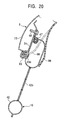
airbag 10 has afirst expansion area 42 which is expanded to cover thewindows front door 85 and therear door 89 continuously. As shown in Fig. 19, a rear end of a flat belt typefront connecting member 51 is sewed and fixedly attached to a front lower end of thefirst expansion area 42 of theairbag 10, and a front end offront connecting member 51 is also connected to a frontrotary hook 52. The frontrotary hook 52 is rotatably connected to theinner panel 74 of thefront pillar 3 by a connectingbolt 53. The front rotary hook is rotated together with the front connectingmember 51 around the connectingbolt 53 as thefirst expansion area 42 of theairbag 10 is expanded. Thus the front pillar trim 95 is disengaged from theengaging rib 93a of the seamingwelt 93 and the edge of the front pillar trim 95 is moved toward the vehicle compartment and eventually the front connectingmember 51 is moved into the vehicle compartment through the opening between the edge of the front pillar trim 95 and theinner panel 74. - On the other hand, as shown in Fig. 14, a front end of a
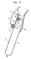
rear connecting member 54 having a similar shape to thefront connecting member 51 is sewed and fixedly attached to a rear lower end of thefirst expansion area 42 of theairbag 10. A rear end of the rear connecting member is also connected to a rearrotary hook 55. This rearrotary hook 55 is similar to the frontrotary hook 52. The rear rotary hook is rotatably connected to theinner panel 74 positioned frontward more than therear pillar 5 through a connectingbolt 56. The rear rotary hook is rotated together with therear connecting member 54 around the connectingbolt 56 as thefirst expansion area 42 of theairbag 10 is expanded. Thus the rear pillar trim 97 is disengaged from theengaging rib 93a of the seamingwelt 93 and the edge of the rear pillar trim 97 is moved toward the inside of the compartment. Eventually therear connecting member 54 is moved into the inside of the vehicle compartment through the opening between the edge of the rear pillar trim 37 and theinner panel 74. - The rear end of the front connecting
member 51 is passed through asquare opening 42a formed on a front lower end of thefirst expansion area 42 of theairbag 10 from an outer side with respect to the vehicle compartment, and then is turned frontward and sewed to a front side portion of theopening 42a. On the other hand, the front end of therear connecting member 54 is passed through anopening 44 formed between the rear lower end of thefirst expansion area 42 of theairbag 10 and a front lower end of asecond expansion area 43 described later from an outer side with respect to the vehicle compartment, and then is turned frontward and sewed to a front side of the opening 44 (first expansion area 42). Each of the connectingmembers airbag 10 by the expansion of the airbag to make a substantial length of the connectingmembers airbag 10 is provided by this shortened length of the connecting members. A position to which the tension is provided is set in an effective height, for example, a height at which an impact at the time when the occupant P1, P2 in the vehicle compartment secondarily collides with thewindow glass 27,31 can be absorbed or the occupant P1, P2 can be prevented from being thrown out of the compartment. - The
airbag 10 also has thesecond expansion area 43 which is to be expanded in a rear side of the fixing portion of therear connecting member 54 to theairbag 10 to cover approximately all of therear pillar 4. The second expansion area is connected to a rear end of thefirst expansion area 42 with allowing the gas communication therebetween. Theopening 44 is formed between theareas second expansion area 43 of theairbag 10 is expanded to overlap with therear pillar 4 located on the side of the occupant P2 seated on therear seat 81 when viewed from the side of the vehicle. As shown in Fig. 14, the rear end portion of thefirst expansion area 42 andsecond expansion area 43 of theairbag 10 and therear connecting member 54 are housed in the rear trim 97 (in a space between therear trim 97 and theinner panel 74 of the rear pillar 4) and these are run out from a front end of therear trim 97 in the expansion of the airbag. - As shown in Fig. 15, on the
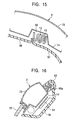
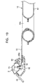
inner panel 74 of theroof rail 5 on therear pillar 4, the rear pillar trim 97 covering therear pillar 4 and the roof trim 98 covering theroof rail 5 are disposed with overlapping a edge of the roof trim 98 onto a edge of the rear pillar trim 97. Aguide recess 58 is formed on theinner panel 74 at a portion corresponding to an overlapping of thetrims second expansion area 43 of theairbag 10 is fold and housed in theguide recess 58 to guide an expanding direction of thesecond expansion area 43. Thus, when thesecond expansion area 43 of theairbag 10 is expanded, the expandingairbag 10 pushes out the edge of the roof trim 98 which is overlapped to the rear pillar trim 97, via the rear pillar trim 97 to expand into the vehicle compartment. - A part of the
gas supply pipe 45 is inserted into and through thesecond expansion area 43 of theairbag 10. Twodischarge ports second expansion area 43 is smaller than that of thefirst expansion area 42, the number of thedischarge port 46 per unit volume of thesecond expansion area 43 is larger than that of thefirst expansion area 42. Accordingly thesecond expansion area 43 of theairbag 10 is expanded more quickly than thefirst expansion area 42. - In addition, since the inflator 49 is disposed on a lower end portion of the
rear pillar 4, the gas is introduced into thegas supply pipe 45 from a rear side of the vehicle body 1, which also assist an earlier expansion of thesecond expansion area 43 of theairbag 10 comparing with thefirst expansion area 42. - As shown in Fig. 12, an
airbag control unit 60 for controlling an actuation of the inflator 49 is disposed on theinstrument panel 18, and animpact sensor 61 for detecting an impact in the side impact of the vehicle is disposed on a lower portion of thecenter pillar 4. - A
non-expansive area 42b is formed on thefirst expansion area 42 of theairbag 10 at a portion positioned approximately corresponding to a front portion of thewindow 90 of therear door 89. Thenon-expansive area 42b is formed by sewing an outer side sheet and an inner side sheet of theairbag 10 together so as to almost came in contact with each other. This prevents an excessive lateral expansion of theairbag 10, and therefore an inner surface of theairbag 10 can be prevented from coming close to the occupant. - Accordingly, in this device, when the impact load is acted on the side of the vehicle 1 in the side impact of the vehicle or the like, the
impact sensor 61 detects it, and, upon receiving an output signal from theimpact sensor 61, theairbag control unit 60 actuates the inflator 49 to generate a high pressure gas. This high pressure gas is introduced into theairbag 10 through thegas supply pipe 45 and thedischarge ports airbag 10. Thus the expandingairbag 10 disengages each of thetrims engaging rib 93a of the seamingwelt 93 and then expands through the opening between each of thetrims inner panel 74 into the compartment. - The
airbag 10 is expanded separately into thefirst expansion area 42 covering most area and thesecond expansion area 43 covering rear end area. Hereat thefirst expansion area 42 is expanded to cover thewindows rear doors first expansion area 42 of theairbag 10, each of the front and therear connecting members inner panel 74 respectively and is pulled by theairbag 10. Thus the longitudinal tension is provided to the lower portion of theairbag 10 by the connectingmembers window glasses windows - On the other hand, the
second expansion area 43 of theairbag 10 is expanded in the rear side of thefirst expansion area 42 to cover almost all of therear pillar 4. According to this, when the occupant P2 seated on therear seat 81 secondarily collides with therear pillar 4, the impact to the occupant P2 can be absorbed and mitigated by thesecond expansion area 43. Since thesecond expansion area 43 is expanded in a rear side area of the fixing portion of therear connecting member 54 to theairbag 10 and makes a soft area where no longitudinal tension is provided by the front and therear connecting members second expansion area 43 provides an impact absorbing characteristic superior to that of thefirst expansion area 42 where the tension is provided by the connectingmembers rear pillar 4 is disposed on the side of the occupant P2 seated on therear seat 81 and thesecond expansion area 43 of theairbag 10 is expanded so as to overlap with therear pillar 4 when viewed from the side of the vehicle, a reaction force of the impact generated by the collision of the occupant P2 seated on therear seat 81 toward therear pillar 5 when the impact load is acted on the side of the vehicle body 1 can be supported by therear pillar 4. Thereby, the impact on the occupant P2 seated on therear seat 81 can be surely absorbed and mitigated. - A rear end portion of the
first expansion area 42 and thesecond expansion area 43 of theairbag 10 and therear connecting member 54 are housed in the pillar trim 97 covering therear pillar 4 in the vehicle compartment, and are run out the front end of the rear pillar trim 97 to be expanded into the compartment. Thus, both of the rear end portion of thefirst expansion area 42 of theairbag 10 to be expanded in a front side of the front end of the rear pillar trim 97 and thesecond expansion area 43 to be expanded in a rear side of the front end of the rear pillar trim 97 can be housed to be hidden from the inside of the vehicle compartment, and thereby theairbag 10 can be housed while keeping good appearance. - The
second expansion area 43 of theairbag 10 is expanded earlier than thefirst expansion area 42. This makes it sure further to protect the occupant P2 seated on therear seat 81 even when therear pillar 4 is protruded more toward the vehicle compartment comparing with thewindows rear doors 85, 99 by the rear pillar trim 97 and is located closer to the occupant P2 seated on therear seat 81, because thesecond expansion area 43 positioned corresponding to therear pillar 5 which is disposed close to the occupant P2 is expanded earlier. - In the above device, while the
rear connecting member 54 is connected to the rear end of thefirst expansion area 42 of theairbag 10 and thesecond expansion area 43 of theairbag 10 is also expanded rearward more than the fixing portion where therear connecting member 54 is fixed to theairbag 10, another arrangement may be alternatively employed. That is, therear connecting member 54 may be connected to the rear end of thesecond expansion area 43 of theairbag 10, and thesecond expansion area 43 of theairbag 10 may be expanded into the vehicle compartment positioned rearward more than an exit portion through which thefirst expansion area 42 is expanded into thevehicle compartment 2. In this case, when theairbag 10 is expanded, the impact at the time when the occupant P2 seated on therear seat 81 secondarily collides with therear pillar 5 can be absorbed and mitigated by thesecond expansion area 43. - While, in the above device, the
second expansion area 43 of theairbag 10 is expanded to cover almost of all therear pillar 5, it may be expanded to cover at least a part of therear pillar 4. - Though, in the above device, the
airbag 10 is housed along thefront pillar 2, theroof rail 5 and therear pillar 4 of the vehicle body 1, it may be housed at least along theroof rail 5. - Though, in the above device, the impact at the time when the occupant P2 seated on the
rear seat 81 secondarily collides with therear pillar 5 disposed on the side of the occupant is absorbed by thesecond expansion area 43 of theairbag 10, this concept may be applied to another case where the impact at the time when the occupant P1 seated on thefront seat 75 secondarily collides with thecenter pillar 3 may be absorbed in the same manner on the assumption that thecenter pillar 3 is replaced by a virtualrear pillar 4. - Further, the present invention is not limited to the vehicle of the above embodiment having two
doors - The present invention is not limited to the embodiment described above, but includes various types of possible embodiments. That is, though the slack absorbing device S for absorbing the slack of the tether is applied to the front side of the
airbag 10 in the one embodiment and another type slack absorbing device S' is applied to the rear side of theairbag 10 in another the embodiment, the arrangement is not limited to these manners, but either of the slack absorbing devices S or S' can be applied to either of the front or the rear side of the airbag.
Claims (1)
- An occupant protection device of a vehicle, wherein said vehicle includes a front side pillar (2) and a rear side pillar (4) disposed on front and rear sides of a side window (7, 9) of said vehicle respectively, and a roof side rail (5) longitudinally extended to connect respective upper ends of said both pillars with each other, said occupant protection device comprising: an airbag (10) which is folded and housed in the range from said front side pillar (2) to said rear side pillar (4) through said roof side rail (5) so that said airbag (10) is expanded to cover an inside of said side window (7, 9) when an impact load is acted on a side of said vehicle, an upper edge of said airbag (10) being fixed to at least said roof side rail (5); a front connecting member (18) for connecting a front lower end of said airbag (10) to a body of said vehicle positioned frontward more than said side window (7, 9);
a rear connecting member (19) for connecting a rear lower end of said airbag (10) to a body of said vehicle positioned rearward more than said side window (7, 9); and
a slack absorbing device (S') for absorbing a slack in said connecting members (17, 19) in an expanded condition of said airbag (10); wherein
at least one of said connecting members (19) includes a first end connected to said airbag (10) and a second end connected to said body (1), said first end being disposed upward more than said second end in the housed condition of said airbag (10), characterised in that
said slack absorbing device (S') is disposed between at least one of said connecting members (19) and a body of said vehicle (1), and includes a guide member (33) for guiding said at least one of said connecting members (19) with making said at least one of said connecting members (19) bend when said first end is moved downward in the expansion condition of said airbag (10), and
said guide member (33) includes a bank portion (33a) for pushing said at least one of said connecting members (19) in the inward direction with respect to a compartment of said vehicle in the expansion condition of said airbag (10).
Applications Claiming Priority (4)
| Application Number | Priority Date | Filing Date | Title |
|---|---|---|---|
| JP19728099 | 1999-07-12 | ||
| JP19728099A JP3812228B2 (en) | 1999-07-12 | 1999-07-12 | Vehicle occupant protection device |
| JP21722799 | 1999-07-30 | ||
| JP21722799A JP3788118B2 (en) | 1999-07-30 | 1999-07-30 | Vehicle occupant protection device |
Publications (2)
| Publication Number | Publication Date |
|---|---|
| EP1069007A1 EP1069007A1 (en) | 2001-01-17 |
| EP1069007B1 true EP1069007B1 (en) | 2004-06-16 |
Family
ID=26510279
Family Applications (1)
| Application Number | Title | Priority Date | Filing Date |
|---|---|---|---|
| EP00114040A Expired - Lifetime EP1069007B1 (en) | 1999-07-12 | 2000-07-05 | Occupant protection device of vehicle |
Country Status (3)
| Country | Link |
|---|---|
| US (1) | US6375214B1 (en) |
| EP (1) | EP1069007B1 (en) |
| DE (1) | DE60011519T2 (en) |
Families Citing this family (39)
| Publication number | Priority date | Publication date | Assignee | Title |
|---|---|---|---|---|
| US6530595B2 (en) * | 1998-08-20 | 2003-03-11 | Takata Corporation | Protective cushion for vehicle occupant's head |
| DE29822768U1 (en) * | 1998-12-21 | 2000-05-04 | Lear Corporation GmbH & Co. KG, 65462 Ginsheim-Gustavsburg | Cladding module |
| JP3705537B2 (en) * | 2000-04-28 | 2005-10-12 | 河西工業株式会社 | Pillar trim mounting structure |
| DE10042419A1 (en) * | 2000-08-30 | 2002-03-14 | Daimler Chrysler Ag | Roof covering for an interior of a vehicle with side impact protection |
| US6851710B2 (en) * | 2001-03-06 | 2005-02-08 | Autoliv Asp, Inc. | Apparatus and method for rapid airbag component installation |
| US7100939B2 (en) * | 2001-03-13 | 2006-09-05 | Trw Automotive U.S. Llc | Inflatable curtain assembly |
| DE20107578U1 (en) * | 2001-05-04 | 2001-07-12 | Breed Automotive Tech | Curtain airbag module |
| US6783152B2 (en) * | 2001-05-23 | 2004-08-31 | Toyoda Gosei Co., Ltd. | Head protecting airbag device |
| US6709010B2 (en) * | 2001-11-09 | 2004-03-23 | Autoliv Asp, Inc. | Rear tether retractor for an inflatable cushion |
| JP3700054B2 (en) * | 2001-11-12 | 2005-09-28 | トヨタ自動車株式会社 | Airbag device |
| US6695347B2 (en) * | 2001-11-29 | 2004-02-24 | Autoliv Asp, Inc. | Self-adjusting tether strap for inflatable curtain |
| US6517104B1 (en) * | 2002-01-28 | 2003-02-11 | Ford Global Technologies, Inc. | Air bag for third row vehicle passengers |
| JP3925226B2 (en) * | 2002-02-12 | 2007-06-06 | タカタ株式会社 | Curtain airbag and curtain airbag device |
| JP4063095B2 (en) * | 2002-03-08 | 2008-03-19 | 豊田合成株式会社 | Head protection airbag device |
| US6889999B2 (en) * | 2002-03-20 | 2005-05-10 | Autoliv Asp, Inc. | Airbag tether retainer |
| JP3879553B2 (en) * | 2002-03-20 | 2007-02-14 | 三菱自動車工業株式会社 | Vehicle occupant protection device |
| US6886858B2 (en) * | 2002-07-26 | 2005-05-03 | Key Safety Systems, Inc. | Air bag assembly with tethers in a woven cushion and method of construction |
| JP2005029036A (en) * | 2003-07-07 | 2005-02-03 | Toyoda Gosei Co Ltd | Head part protecting air bag device |
| US7125038B2 (en) * | 2003-10-27 | 2006-10-24 | Autoliv Asp, Inc. | Twist prevention apparatus and method for an inflatable airbag curtain |
| US20050206135A1 (en) * | 2003-10-27 | 2005-09-22 | Nelson James E | Curtain airbag handling device |
| US7404571B2 (en) * | 2004-02-26 | 2008-07-29 | Automotive Systems Laboratory, Inc. | Linear inflator and mounting clip |
| EP1855919B1 (en) * | 2005-03-02 | 2010-11-03 | Autoliv Development AB | Tubular gas guiding element, a gas generating and supplying unit and a suspended gasbag unit |
| US20060237957A1 (en) * | 2005-04-22 | 2006-10-26 | Takata Restraint Systems, Inc. | Sealed cushion |
| DE602007000384D1 (en) * | 2006-03-07 | 2009-02-05 | Mazda Motor | Rear part of a motor vehicle with side airbag device |
| US20080061604A1 (en) * | 2006-09-12 | 2008-03-13 | Tiesler John M | Modular vehicle headliner |
| US7571930B2 (en) * | 2007-08-31 | 2009-08-11 | Nissan Technical Center North America, Inc. | Inflatable curtain airbag integrated tether |
| DE102008026817A1 (en) * | 2008-06-05 | 2009-12-10 | GM Global Technology Operations, Inc., Detroit | Pillar of a motor vehicle |
| US7823922B2 (en) * | 2008-07-16 | 2010-11-02 | Autoliv Asp, Inc. | Tether systems for inflatable cushions |
| CN102300750B (en) | 2009-02-03 | 2014-10-15 | 丰田自动车株式会社 | Car head protection airbag device |
| JP5623355B2 (en) * | 2010-07-30 | 2014-11-12 | オートリブ ディベロップメント エービー | Curtain airbag |
| DE102011076056B4 (en) * | 2011-05-18 | 2015-03-05 | TAKATA Aktiengesellschaft | An airbag assembly for a vehicle occupant restraint system and method of manufacturing such an airbag assembly |
| KR101357343B1 (en) * | 2012-11-29 | 2014-02-11 | 쌍용자동차 주식회사 | Curtain airbags integrated extension panel loop side for automobile |
| JP6299426B2 (en) | 2013-09-26 | 2018-03-28 | 豊田合成株式会社 | Head protection airbag device |
| US9156427B2 (en) | 2014-01-08 | 2015-10-13 | Autoliv Asp, Inc. | Cost-effective use of one-piece woven fabric for curtain airbags |
| KR101755952B1 (en) * | 2015-12-29 | 2017-07-10 | 현대자동차주식회사 | Curtain airbag for vehicle |
| JP6575438B2 (en) * | 2016-05-31 | 2019-09-18 | 豊田合成株式会社 | Head protection airbag device |
| JP7070302B2 (en) * | 2018-10-03 | 2022-05-18 | トヨタ自動車株式会社 | Vehicle curtain airbag device |
| US12227140B2 (en) * | 2020-11-25 | 2025-02-18 | ZF Passive Safety Systems US Inc. | Anchorless tether for curtain airbag |
| US11912229B2 (en) | 2021-03-30 | 2024-02-27 | Honda Motor Co., Ltd. | Lid for airbag tether deployment in vehicles |
Family Cites Families (18)
| Publication number | Priority date | Publication date | Assignee | Title |
|---|---|---|---|---|
| EP0814001B2 (en) | 1996-06-23 | 2004-03-03 | HS Technik und Design Technische Entwicklungen GmbH | Airbag device |
| DE29616904U1 (en) * | 1996-09-27 | 1997-01-30 | Trw Repa Gmbh | Protection device for vehicle occupants |
| JP3510061B2 (en) | 1996-11-07 | 2004-03-22 | トヨタ自動車株式会社 | Car occupant protection equipment |
| JP3684723B2 (en) | 1996-12-11 | 2005-08-17 | トヨタ自動車株式会社 | Car occupant protection device |
| DE19704051C2 (en) | 1997-02-04 | 2001-10-18 | Mst Automotive Gmbh | Airbag device |
| GB2324068B (en) | 1997-04-11 | 2001-01-10 | Autoliv Dev | Improvements in or relating to an air-bag arrangement |
| DE29718305U1 (en) | 1997-10-15 | 1998-02-12 | Trw Repa Gmbh | Inflatable protection device for vehicle occupants to protect against a side impact in the head and thorax area |
| DE29803985U1 (en) | 1998-03-06 | 1998-07-02 | Trw Repa Gmbh | Airbag module |
| DE29806200U1 (en) | 1998-04-03 | 1998-09-03 | Trw Repa Gmbh | Inflatable protective cushion to cover the side windows in the vehicle |
| DE19820568A1 (en) | 1998-05-08 | 1999-11-11 | Bayerische Motoren Werke Ag | Inflatable head protection system for the side area of a motor vehicle |
| DE19843402C1 (en) * | 1998-09-22 | 2000-03-16 | Daimler Chrysler Ag | Side impact airbag device |
| DE19843493B4 (en) | 1998-09-22 | 2005-04-28 | Ihd Inst Fuer Holztechnologie | Plate-shaped material made of wood shavings and binders for use in construction and furniture construction and method for its production |
| DE29822617U1 (en) * | 1998-12-18 | 1999-04-08 | Trw Repa Gmbh | Device for inflating a vehicle occupant restraint system |
| US6155597A (en) * | 1999-05-11 | 2000-12-05 | Trw Vehicle Safety Systems Inc. | Vehicle occupant protection device with spring connector |
| US6095551A (en) * | 1999-08-02 | 2000-08-01 | Trw Inc. | Non-inflatable curtain with inflatable device |
| US6168193B1 (en) * | 1999-08-05 | 2001-01-02 | Trw Inc. | Inflatable curtain with tensioning device |
| US6176515B1 (en) * | 1999-10-07 | 2001-01-23 | Trw Vehicle Safety Systems Inc. | Inflatable curtain with positioning device |
| DE20001960U1 (en) | 2000-02-04 | 2000-06-21 | Trw Repa Gmbh | Vehicle occupant restraint system |
-
2000
- 2000-06-29 US US09/605,546 patent/US6375214B1/en not_active Expired - Fee Related
- 2000-07-05 DE DE60011519T patent/DE60011519T2/en not_active Expired - Lifetime
- 2000-07-05 EP EP00114040A patent/EP1069007B1/en not_active Expired - Lifetime
Also Published As
| Publication number | Publication date |
|---|---|
| EP1069007A1 (en) | 2001-01-17 |
| DE60011519D1 (en) | 2004-07-22 |
| US6375214B1 (en) | 2002-04-23 |
| DE60011519T2 (en) | 2005-08-25 |
Similar Documents
| Publication | Publication Date | Title |
|---|---|---|
| EP1069007B1 (en) | Occupant protection device of vehicle | |
| US6059311A (en) | Pillar-mounted side impact and rollover air bag | |
| KR100252148B1 (en) | A lateral impact protective device for vehicle occupants | |
| US7347444B2 (en) | Inflatable airbag with overlapping chamber | |
| US6394487B1 (en) | Inflatable airbag | |
| EP1054790B1 (en) | Side curtain airbag system | |
| US7806433B2 (en) | Head protecting airbag system | |
| JP3956863B2 (en) | Head protection airbag | |
| US20040075257A1 (en) | Head protecting airbag device | |
| EP1676758B1 (en) | Airbag device and control method therefor | |
| JP2006515544A (en) | Airbag fabric diffuser | |
| US20030132619A1 (en) | Containment impact protection system | |
| EP2151360A1 (en) | An interior structure of a vehicle equipped with a curtain airbag and method of providing it | |
| US6945558B2 (en) | Inflatable curtain support device | |
| JP4273944B2 (en) | Head protection airbag device and vehicle | |
| US7380815B2 (en) | Lower side piller passenger inflatable safety restraint assembly | |
| US7080853B2 (en) | Airbag for head-protecting airbag device | |
| US6729645B2 (en) | Automobile head protection device for vehicle occupant | |
| EP1533196B1 (en) | Airbag system | |
| JP2002505225A (en) | Gas bag module for car occupant restraint | |
| JP3812228B2 (en) | Vehicle occupant protection device | |
| WO2009144971A1 (en) | Head-restraining airbag system | |
| JP2002362288A (en) | Occupant restraint | |
| US20020167154A1 (en) | Head-protecting bag device | |
| EP1953046B1 (en) | Vehicle occupant restraint system |
Legal Events
| Date | Code | Title | Description |
|---|---|---|---|
| PUAI | Public reference made under article 153(3) epc to a published international application that has entered the european phase |
Free format text: ORIGINAL CODE: 0009012 |
|
| AK | Designated contracting states |
Kind code of ref document: A1 Designated state(s): DE ES FR GB IT |
|
| AX | Request for extension of the european patent |
Free format text: AL;LT;LV;MK;RO;SI |
|
| 17P | Request for examination filed |
Effective date: 20010405 |
|
| AKX | Designation fees paid |
Free format text: DE ES FR GB IT |
|
| 17Q | First examination report despatched |
Effective date: 20020906 |
|
| GRAP | Despatch of communication of intention to grant a patent |
Free format text: ORIGINAL CODE: EPIDOSNIGR1 |
|
| GRAS | Grant fee paid |
Free format text: ORIGINAL CODE: EPIDOSNIGR3 |
|
| GRAA | (expected) grant |
Free format text: ORIGINAL CODE: 0009210 |
|
| AK | Designated contracting states |
Kind code of ref document: B1 Designated state(s): DE ES FR GB IT |
|
| PG25 | Lapsed in a contracting state [announced via postgrant information from national office to epo] |
Ref country code: IT Free format text: LAPSE BECAUSE OF FAILURE TO SUBMIT A TRANSLATION OF THE DESCRIPTION OR TO PAY THE FEE WITHIN THE PRESCRIBED TIME-LIMIT;WARNING: LAPSES OF ITALIAN PATENTS WITH EFFECTIVE DATE BEFORE 2007 MAY HAVE OCCURRED AT ANY TIME BEFORE 2007. THE CORRECT EFFECTIVE DATE MAY BE DIFFERENT FROM THE ONE RECORDED. Effective date: 20040616 Ref country code: FR Free format text: LAPSE BECAUSE OF NON-PAYMENT OF DUE FEES Effective date: 20040616 |
|
| REG | Reference to a national code |
Ref country code: GB Ref legal event code: FG4D |
|
| REF | Corresponds to: |
Ref document number: 60011519 Country of ref document: DE Date of ref document: 20040722 Kind code of ref document: P |
|
| PG25 | Lapsed in a contracting state [announced via postgrant information from national office to epo] |
Ref country code: GB Free format text: LAPSE BECAUSE OF NON-PAYMENT OF DUE FEES Effective date: 20040916 |
|
| PG25 | Lapsed in a contracting state [announced via postgrant information from national office to epo] |
Ref country code: ES Free format text: LAPSE BECAUSE OF FAILURE TO SUBMIT A TRANSLATION OF THE DESCRIPTION OR TO PAY THE FEE WITHIN THE PRESCRIBED TIME-LIMIT Effective date: 20040927 |
|
| PLBE | No opposition filed within time limit |
Free format text: ORIGINAL CODE: 0009261 |
|
| STAA | Information on the status of an ep patent application or granted ep patent |
Free format text: STATUS: NO OPPOSITION FILED WITHIN TIME LIMIT |
|
| GBPC | Gb: european patent ceased through non-payment of renewal fee |
Effective date: 20040916 |
|
| 26N | No opposition filed |
Effective date: 20050317 |
|
| EN | Fr: translation not filed | ||
| PGFP | Annual fee paid to national office [announced via postgrant information from national office to epo] |
Ref country code: DE Payment date: 20110629 Year of fee payment: 12 |
|
| PG25 | Lapsed in a contracting state [announced via postgrant information from national office to epo] |
Ref country code: DE Free format text: LAPSE BECAUSE OF NON-PAYMENT OF DUE FEES Effective date: 20130201 |
|
| REG | Reference to a national code |
Ref country code: DE Ref legal event code: R119 Ref document number: 60011519 Country of ref document: DE Effective date: 20130201 |