EP1068971A1 - A folding roof for a vehicle - Google Patents
A folding roof for a vehicle Download PDFInfo
- Publication number
- EP1068971A1 EP1068971A1 EP00202269A EP00202269A EP1068971A1 EP 1068971 A1 EP1068971 A1 EP 1068971A1 EP 00202269 A EP00202269 A EP 00202269A EP 00202269 A EP00202269 A EP 00202269A EP 1068971 A1 EP1068971 A1 EP 1068971A1
- Authority
- EP
- European Patent Office
- Prior art keywords
- engagement
- roof
- opening
- cover
- folding
- Prior art date
- Legal status (The legal status is an assumption and is not a legal conclusion. Google has not performed a legal analysis and makes no representation as to the accuracy of the status listed.)
- Granted
Links
- 229910000831 Steel Inorganic materials 0.000 description 1
- 230000000694 effects Effects 0.000 description 1
- 238000007789 sealing Methods 0.000 description 1
- 239000010959 steel Substances 0.000 description 1
Images

Classifications
-
- B—PERFORMING OPERATIONS; TRANSPORTING
- B60—VEHICLES IN GENERAL
- B60J—WINDOWS, WINDSCREENS, NON-FIXED ROOFS, DOORS, OR SIMILAR DEVICES FOR VEHICLES; REMOVABLE EXTERNAL PROTECTIVE COVERINGS SPECIALLY ADAPTED FOR VEHICLES
- B60J7/00—Non-fixed roofs; Roofs with movable panels, e.g. rotary sunroofs
- B60J7/02—Non-fixed roofs; Roofs with movable panels, e.g. rotary sunroofs of sliding type, e.g. comprising guide shoes
- B60J7/06—Non-fixed roofs; Roofs with movable panels, e.g. rotary sunroofs of sliding type, e.g. comprising guide shoes with non-rigid element or elements
- B60J7/061—Non-fixed roofs; Roofs with movable panels, e.g. rotary sunroofs of sliding type, e.g. comprising guide shoes with non-rigid element or elements sliding and folding
- B60J7/064—Non-fixed roofs; Roofs with movable panels, e.g. rotary sunroofs of sliding type, e.g. comprising guide shoes with non-rigid element or elements sliding and folding using folding arms sliding in longitudinal tracks for supporting the soft roof
Definitions
- the invention relates to a folding roof in accordance with the preamble of claim 1.
- the tensioning elements in the form of tensioning wires extend alternately under the first supporting bows and over the second supporting bows, and in this manner the second supporting bows are loaded in downward direction by the tensioning wires when the folding roof is in the closed position.
- the object of the present invention is to provide an improved folding roof of the kind referred to in the introduction.
- the folding roof according to the invention is characterized by the features of claim 1.
- This manner of guiding the tensioning wires via second sliding shoes enables a better tensioning characteristic of the tensioning wires. Especially if the tensioning wires extend steeply adjacently to the points of engagement at the second supporting bows, a considerable part of the tensioning force in the tensioning wires will actually be used for exerting a downward force on the second supporting bows. This makes it possible to realise a better seal and a better protection against a possible break-in via the folding roof. Furthermore, the first supporting bows need not absorb any downward force from the tensioning elements in the closed position of the folding roof, as a result of which a better seal can be obtained at that location as well.
- Fig. 1 shows a fixed roof 1 of a vehicle, in particular a passenger car, which is provided with a roof opening 2 for accommodating a folding roof.
- the folding roof comprises a stationary part, in this embodiment in the form of a window-shaped frame 3, which is attached to the fixed roof 1 and which circumferentially bounds a passage 4 of the folding roof.
- Passage 4 can be selectively covered or opened by means of a foldable cover 5.
- cover 5 is attached to frame 3 at the rear side of the vehicle, and at the front side said cover 5 is connected to an operating beam 6 or the like.
- Operating beam 6 can be moved by means of an operating mechanism, with an electric motor 7 and driving cables 8 acting as drive in this embodiment. This will not be discussed in more detail herein.
- the operating beam 6 is guided in guide rails 9 via sliding shoes at both ends, which guide rails extend in the longitudinal direction of the vehicle on either side of passage 4.
- foldable cover 5 is supported by a number of supporting bows, two supporting bows 10, 11 of a first kind and three supporting bows 12, 13, 14 of a second kind in this embodiment.
- the supporting bows of the first and the second kind alternate.
- the supporting bows of the first and the second kind will also be referred to as first and second supporting bows.
- the second supporting bows 12, 13, 14 are vertically movable or free supporting bows, which are either connected, via arms 15, to operating beam 6 (see supporting bow 12) at both ends or to the preceding first supporting bow 10 or 11 (this holds for second supporting bows 13 and 14).
- Arms 15 are resilient arms, which are biassed in upward direction.
- Fig. 1, 2 and 3 show that not only the first supporting bows 10 and 11 are fitted with first sliding shoes 16, 17, but that second sliding shoes 18, 19, 20 are provided near the second supporting bows 12, 13, 14. Said second sliding shoes 18, 19, 20 function to guide an elongated tensioning element in the form of tensioning wires 23 and 24, respectively, which are provided at respective longitudinal edge of passage 4.
- the front end of tensioning wires 23, 24 is connected to the driving means, to operating beam 6 in this case.
- the end of tensioning wires 23, 24 remote from the driving means, the rear end in this case, is attached to frame 3, via an adjusting arrangement (not shown), if necessary, by means of which the tensioning element can be adjusted and be readjusted in the course of the life of the folding roof.
- Tensioning wires 23 and 24 are intended to push the longitudinal edges of the cover firmly down onto the upper side of frame 3 in the closed position of the folding roof, which makes it possible to achieve a proper seal and protection against theft.
- tensioning wire 23 which may be a plastic-coated steel cable, for example, is guided into second sliding shoe 18 from the front side near supporting bow 13, and subsequently out again through an opening in the upper side of second sliding shoe 19.
- tensioning wire 23 is passed over a pin or pulley 25 near the end of second supporting bow 13, and subsequently back again through the opening in the upper side of second sliding shoe 19, and finally out again through an opening at the rear side of second sliding shoe 19.
- a variable loop 26 is formed in tensioning wire 23 above second sliding shoe 23, which loop is passed over the pulley 25 of second supporting bow 13.
- the invention provides a folding roof for a vehicle which is remarkable for the simple and adequate manner in which the edges of the cover are held down.
- the invention is not limited to the embodiment as described above and shown in the drawing, which can be varied in several ways without departing from the scope of the invention.
- the tensioning wires could also be passed over the respective second supporting bows themselves.
- tensioning wires it is also possible to use other elongated tensioning elements.
- the invention is also useful in folding roofs which do not have supporting bows, but which have a self-supporting cover, for example incorporating rigid stiffening plates. In that case, there will be folding means only at the sides of the cover adjacent the guide rails.
- the invention can also be used with folding roofs which can (also) be opened at the rear side.
Landscapes
- Engineering & Computer Science (AREA)
- Mechanical Engineering (AREA)
- Tents Or Canopies (AREA)
- Body Structure For Vehicles (AREA)
- Seal Device For Vehicle (AREA)
Abstract
Description
- The invention relates to a folding roof in accordance with the preamble of
claim 1. - In a prior art embodiment of such a folding roof, the tensioning elements in the form of tensioning wires extend alternately under the first supporting bows and over the second supporting bows, and in this manner the second supporting bows are loaded in downward direction by the tensioning wires when the folding roof is in the closed position.
- The object of the present invention is to provide an improved folding roof of the kind referred to in the introduction.
- In order to accomplish that objective, the folding roof according to the invention is characterized by the features of
claim 1. - This manner of guiding the tensioning wires via second sliding shoes enables a better tensioning characteristic of the tensioning wires. Especially if the tensioning wires extend steeply adjacently to the points of engagement at the second supporting bows, a considerable part of the tensioning force in the tensioning wires will actually be used for exerting a downward force on the second supporting bows. This makes it possible to realise a better seal and a better protection against a possible break-in via the folding roof. Furthermore, the first supporting bows need not absorb any downward force from the tensioning elements in the closed position of the folding roof, as a result of which a better seal can be obtained at that location as well.
- The invention will be explained in more detail hereafter with reference to the drawing, which schematically shows an exemplary embodiment of the folding roof according to the invention.
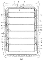
- Fig. 1 is a very schematic top plan view of the exemplary embodiment of the folding roof according to the invention.
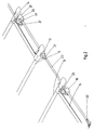
- Fig. 2 is a larger-scale, perspective view of one end of the three rear supporting bows and the associated tensioning wire, in the closed position of the folding roof.
- Fig. 3 is a perspective view of the supporting bows of Fig. 2 in the open position of the folding roof.
-
- Fig. 1 shows a
fixed roof 1 of a vehicle, in particular a passenger car, which is provided with a roof opening 2 for accommodating a folding roof. The folding roof comprises a stationary part, in this embodiment in the form of a window-shaped frame 3, which is attached to thefixed roof 1 and which circumferentially bounds a passage 4 of the folding roof. - Passage 4 can be selectively covered or opened by means of a foldable cover 5. In the illustrated embodiment, cover 5 is attached to
frame 3 at the rear side of the vehicle, and at the front side said cover 5 is connected to anoperating beam 6 or the like.Operating beam 6 can be moved by means of an operating mechanism, with anelectric motor 7 and drivingcables 8 acting as drive in this embodiment. This will not be discussed in more detail herein. Theoperating beam 6 is guided inguide rails 9 via sliding shoes at both ends, which guide rails extend in the longitudinal direction of the vehicle on either side of passage 4. - In order to ensure that cover 5 is folded in a controlled manner when the folding roof is being opened, foldable cover 5 is supported by a number of supporting bows, two supporting
bows bows - From Fig. 1, when viewed in combination with Fig. 2 and 3, it can be concluded that the second supporting
bows arms 15, to operating beam 6 (see supporting bow 12) at both ends or to the preceding first supportingbow 10 or 11 (this holds for second supportingbows 13 and 14).Arms 15 are resilient arms, which are biassed in upward direction. - When operating
beam 6 and thus the front ends of the associatedarms 15 are moved to the rear, therefore, the distance to the first supportingbow 10, which is connected toguide rail 9 by means of a connectingmember 21, will decrease, which results in some slackness in cover 5, which makes it possible for the supporting second supporting bow 12 to be pushed upward byarms 15. Eventually a rearwardly sloping fold will be formed in cover 5, with the second supporting bow 12 positioned at the top of said fold, andoperating beam 6 will come into contact with first slidingshoes 16, which slidably support first supportingbow 10. The connectingmember 21, which is in engagement withguide rail 9, will be disconnected from first slidingshoes 16 by means of a disconnectingelement 22 ofoperating beam 6, as a result of which also the first supportingbow 10 will move rearwards. The same will subsequently happen with the first supportingbow 11 and second supportingbows - Fig. 1, 2 and 3 show that not only the first supporting
bows shoes shoes bows sliding shoes tensioning wires tensioning wires beam 6 in this case. The end oftensioning wires frame 3, via an adjusting arrangement (not shown), if necessary, by means of which the tensioning element can be adjusted and be readjusted in the course of the life of the folding roof. Tensioningwires frame 3 in the closed position of the folding roof, which makes it possible to achieve a proper seal and protection against theft. - As is shown in Fig. 2 and 3, tensioning
wire 23, which may be a plastic-coated steel cable, for example, is guided into second slidingshoe 18 from the front side near supportingbow 13, and subsequently out again through an opening in the upper side of second slidingshoe 19. At that location tensioningwire 23 is passed over a pin orpulley 25 near the end of second supportingbow 13, and subsequently back again through the opening in the upper side of second slidingshoe 19, and finally out again through an opening at the rear side of second slidingshoe 19. In this way avariable loop 26 is formed in tensioningwire 23 above second slidingshoe 23, which loop is passed over thepulley 25 of second supportingbow 13. The same takes place with second slidingshoe 20 at the rearsecond supporting bow 14, wherebyloop 25 extends forward from the rear, however, and is passed through aneye 27 to pulley 25, as a result of which thetensioning wire 23 is moved in lateral direction and led further rearwards in laterally deflected direction. This is done in order to have the tensioningwire 23 run outside a guiding groove inguide rail 9 behind second slidingshoe 20, so that it will not come into contact with further means which are guided in the guiding groove in question. - As a result of the path of tensioning
wire 23 through second slidingshoes pulleys 25 of the associated supportingbows loops 26 will become larger or smaller upon movement of theoperating beam 6 and thus of the front end oftensioning wire 23. When the folding roof is being closed, the tensioning wire will be tensioned as a result of the forward movement of theoperating beam 6. Tensioningwire 23 is so dimensioned that a tensioning force will be produced in tensioningwire loop 26, with the tensioning wire extending substantially vertically adjacently to pulley 25, the tensioning force in tensioningwire 23 includes a large vertical component at that location. As a result of this, a large part of the tensioning force is converted into a downward force on second supportingbows frame 3, thus providing an adequate seal and a proper protection against possible break-in. Eachtensioning wire bows bows - From the foregoing it will be apparent that the invention provides a folding roof for a vehicle which is remarkable for the simple and adequate manner in which the edges of the cover are held down.
- The invention is not limited to the embodiment as described above and shown in the drawing, which can be varied in several ways without departing from the scope of the invention. Thus the tensioning wires could also be passed over the respective second supporting bows themselves. Furthermore it would be possible to pass the tensioning wires over the first supporting bows as well. Instead of tensioning wires, it is also possible to use other elongated tensioning elements. The invention is also useful in folding roofs which do not have supporting bows, but which have a self-supporting cover, for example incorporating rigid stiffening plates. In that case, there will be folding means only at the sides of the cover adjacent the guide rails. The invention can also be used with folding roofs which can (also) be opened at the rear side.
Claims (9)
- A folding roof for a vehicle having an opening (2) in its fixed roof (1), comprising a stationary part (3) to be fixed to the roof, which includes guide rails (9) present at the longitudinal edges of the opening (2), an adjustable closure element (5, 6) supported by said stationary part, which is adjustable between a closed position, in which it closes the roof opening, and an open position, in which it releases the roof opening on the opening side, wherein the closure element (5, 6) includes an operating beam (6) extending in transverse direction, which is connected to driving means (7, 8), on the opening side and a foldable cover (5) attached thereto, which cover is alternately supported by first supporting bows (10, 11) extending in transverse direction, which are supported at their ends by first sliding shoes (16, 17) guided in said guide rails (19), as well as by vertically adjustable second supporting bows (12 - 14) extending in transverse direction, which are adjustably supported at their ends by means of connecting members (15), wherein elongated tensioning elements (23, 24) are guided along said guide rails (19), which tensioning elements engage said second supporting bows (12 - 14) via at least one point of engagement (25) and which are connected to said driving means (6 - 8), in such a manner that they are tensioned when the cover (5) is being closed, thereby exerting a downward force on the second supporting bows (12 - 14) via said points of engagement, characterised in that each tensioning element (23, 24) is guided via an associated second sliding shoe (18 - 20) on either side of the points of engagement (25) of the second supporting bows (12 - 14), preferably in such a manner that the tensioning element (23, 24) extends steeply adjacently to the point of engagement (25) in the closed position of the cover (5).
- A folding roof according to claim 1, wherein each tensioning element (23, 24) extends at least substantially vertically adjacently to each point of engagement (25) in the closed position of the cover (5).
- A folding roof according to claim 1, wherein each tensioning element (23, 24) is guided out of the respective second sliding shoes (18 - 20) and passed over the associated points of engagement (25) in the form of a loop (26).
- A folding roof according to claim 3, wherein each point of engagement (25) is in the form of a pulley-like element, which is disposed laterally of the associated second supporting bow (12 - 14).
- A folding roof according to claim 1, wherein the second supporting bows (12 - 14) are pivotally connected to a preceding first supporting bow (10, 11) and to the operating beam (6) by means of a, preferably resilient, arm as the connecting member (15).
- A folding roof according to claim 1, wherein the second sliding shoes (18 - 20) are freely guided in the respective guide rail (9), whilst the first sliding shoes (16, 17) are provided with connecting members (21) for connecting said first sliding shoes to said guide rails (9).
- A folding roof according to claim 1, wherein each tensioning element (23, 24) is moved in lateral direction at the rear second supporting bow (14) and led further rearwards in laterally deflected direction.
- A folding roof according to claim 1, wherein the tensioning elements (23, 24) are connected to said driving means (6 - 8) at one end, whilst they are attached to the stationary part (3) and the guide rails (9), respectively, via an adjusting arrangement at the other end.
- A folding roof for a vehicle having an opening (2) in its fixed roof (1), comprising a stationary part (3) to be fixed to the roof, which includes guide rails (9) present at the longitudinal edges of the opening (2), an adjustable closure element (5, 6) supported by said stationary part, which is adjustable between a closed position, in which it closes the roof opening, and an open position, in which it releases the roof opening on the opening side, wherein the closure element (5, 6) includes an operating beam (6) extending in transverse direction, which is connected to driving means (7, 8), on the opening side and a foldable cover (5) attached thereto, which cover is supported at least by vertically adjustable folding means (12 - 14), which are adjustably supported near the guide rails by means of connecting members (15), wherein elongated tensioning elements (23, 24) are guided along said guide rails (19), which engage said folding means (12 - 14) via at least one point of engagement (25) and which are connected to said driving means (6 - 8), in such a manner that they are tensioned when the cover (5) is being closed, thereby exerting a downward force on the folding means (12 - 14) via said points of engagement, characterised in that each tensioning element (23, 24) is guided via an associated second sliding shoe (18 - 20) on either side of the points of engagement (25) of said folding means (12 - 14), preferably in such a manner that the tensioning element (23, 24) extends steeply adjacently to the point of engagement (25) in the closed position of the cover (5).
Applications Claiming Priority (2)
| Application Number | Priority Date | Filing Date | Title |
|---|---|---|---|
| NL1012609A NL1012609C2 (en) | 1999-07-15 | 1999-07-15 | Folding roof for a vehicle. |
| NL1012609 | 1999-07-15 |
Publications (2)
| Publication Number | Publication Date |
|---|---|
| EP1068971A1 true EP1068971A1 (en) | 2001-01-17 |
| EP1068971B1 EP1068971B1 (en) | 2004-10-13 |
Family
ID=19769572
Family Applications (1)
| Application Number | Title | Priority Date | Filing Date |
|---|---|---|---|
| EP00202269A Expired - Lifetime EP1068971B1 (en) | 1999-07-15 | 2000-06-28 | A folding roof for a vehicle |
Country Status (5)
| Country | Link |
|---|---|
| US (1) | US6322137B1 (en) |
| EP (1) | EP1068971B1 (en) |
| JP (1) | JP2001039164A (en) |
| DE (1) | DE60014788T2 (en) |
| NL (1) | NL1012609C2 (en) |
Cited By (1)
| Publication number | Priority date | Publication date | Assignee | Title |
|---|---|---|---|---|
| EP2172355A1 (en) * | 2008-10-01 | 2010-04-07 | Magna Car Top Systems GmbH | Folding roof for the roof of a passenger vehicle |
Families Citing this family (10)
| Publication number | Priority date | Publication date | Assignee | Title |
|---|---|---|---|---|
| NL1013293C2 (en) | 1999-10-14 | 2001-04-18 | Inalfa Ind Bv | Folding roof for vehicle with opening in fixed roof, is provided with stationary part fixable to roof and foldable closure component supportable by stationary part, which by choice can wholly or partly free or close opening |
| US6695385B1 (en) | 2003-03-31 | 2004-02-24 | Asc Incorporated | Vehicle convertible roof |
| US7448667B2 (en) * | 2004-02-27 | 2008-11-11 | Magna Car Top Systems Gmbh | Spring clip for use in a convertible top having side tension cables |
| US6957842B1 (en) * | 2004-04-30 | 2005-10-25 | Asc Incorporated | Convertible roof bow tensioning apparatus |
| US20050280293A1 (en) * | 2004-06-17 | 2005-12-22 | Macnee Arthur L Iii | Automotive vehicle open air system |
| US7163260B2 (en) * | 2004-06-17 | 2007-01-16 | Asc Incorporated | Automotive vehicle open air system |
| US7938483B2 (en) * | 2007-05-24 | 2011-05-10 | Specialty Vehicle Acquisition Corp. | Movable vehicular roof |
| US7527328B2 (en) * | 2007-05-24 | 2009-05-05 | Specialty Vehicle Acquisition Corp. | Modular roof system for automotive vehicle |
| DE102008026548B3 (en) * | 2008-06-03 | 2010-03-04 | Webasto Ag | Folding roof for use as e.g. opening system for folding top for cabriolet, has locking mechanism releasing convertible top bow sliders from slider element during closing of roof opening and during locking of sliders at guide rails |
| CN115972875A (en) * | 2022-12-29 | 2023-04-18 | 浙江零跑科技股份有限公司 | Foldable sunroof and vehicle |
Citations (2)
| Publication number | Priority date | Publication date | Assignee | Title |
|---|---|---|---|---|
| US1786662A (en) * | 1927-04-29 | 1930-12-30 | Leather Felix John | Hood for automobiles and other vehicles |
| EP0376203A2 (en) * | 1988-12-28 | 1990-07-04 | Ohi Seisakusho Co., Ltd. | Canvas top type sunroof structure for motor vehicle |
Family Cites Families (2)
| Publication number | Priority date | Publication date | Assignee | Title |
|---|---|---|---|---|
| FR694099A (en) * | 1929-07-30 | 1930-11-28 | Folding roof portfolio | |
| CH145013A (en) * | 1930-11-28 | 1931-01-31 | Blum Leonhard | Automobile roofing. |
-
1999
- 1999-07-15 NL NL1012609A patent/NL1012609C2/en not_active IP Right Cessation
-
2000
- 2000-06-28 EP EP00202269A patent/EP1068971B1/en not_active Expired - Lifetime
- 2000-06-28 DE DE60014788T patent/DE60014788T2/en not_active Expired - Lifetime
- 2000-07-11 JP JP2000210460A patent/JP2001039164A/en active Pending
- 2000-07-14 US US09/616,162 patent/US6322137B1/en not_active Expired - Fee Related
Patent Citations (2)
| Publication number | Priority date | Publication date | Assignee | Title |
|---|---|---|---|---|
| US1786662A (en) * | 1927-04-29 | 1930-12-30 | Leather Felix John | Hood for automobiles and other vehicles |
| EP0376203A2 (en) * | 1988-12-28 | 1990-07-04 | Ohi Seisakusho Co., Ltd. | Canvas top type sunroof structure for motor vehicle |
Cited By (1)
| Publication number | Priority date | Publication date | Assignee | Title |
|---|---|---|---|---|
| EP2172355A1 (en) * | 2008-10-01 | 2010-04-07 | Magna Car Top Systems GmbH | Folding roof for the roof of a passenger vehicle |
Also Published As
| Publication number | Publication date |
|---|---|
| DE60014788D1 (en) | 2004-11-18 |
| US6322137B1 (en) | 2001-11-27 |
| NL1012609C2 (en) | 2001-01-16 |
| EP1068971B1 (en) | 2004-10-13 |
| DE60014788T2 (en) | 2005-10-20 |
| JP2001039164A (en) | 2001-02-13 |
Similar Documents
| Publication | Publication Date | Title |
|---|---|---|
| EP1068971B1 (en) | A folding roof for a vehicle | |
| US5967593A (en) | Panel cover for a forward area of the frame opening of a top storage compartment | |
| JP5119325B2 (en) | Modular sliding rigid panel roof system | |
| US10399416B2 (en) | Sliding roof system for a motor vehicle | |
| SE454864B (en) | INFALLABLE REAR WINDOW CONSTRUCTION FOR A VEHICLE | |
| US20080067839A1 (en) | Wind Deflector | |
| US6322131B1 (en) | Convertible vehicle with a rear window which can be lowered | |
| EP1813475A1 (en) | Tonneau cover device | |
| EP1232888B1 (en) | Protective cover for guide rail of a vehicle open roof construction | |
| US8657362B2 (en) | Convertible having a roof arrangement | |
| US6481787B1 (en) | Motor vehicle roof with two covers and two head liner parts | |
| EP0376203B1 (en) | Canvas top type sunroof structure for motor vehicle | |
| EP1052126B1 (en) | Open roof construction for a vehicle | |
| JP3884505B2 (en) | Vehicle folding roof | |
| KR20140040019A (en) | Drive mechanism and open roof construction provided therewith | |
| EP1024043B1 (en) | Open roof construction for a vehicle | |
| JP2002036882A (en) | Open roof structure for vehicle | |
| EP1964702B1 (en) | Open roof construction for a vehicle | |
| CN208827552U (en) | Vehicle sun visor | |
| FI98140C (en) | Convertible sunroof locking arrangement | |
| US12528340B2 (en) | Vehicle roof having an openable folding roof with a tensioning cable system | |
| JPS60163723A (en) | Openable roof construction of car | |
| EP0990544A1 (en) | Open roof construction for a vehicle | |
| US7537277B2 (en) | Vehicle roof | |
| KR101846565B1 (en) | Locking apparatus for closing glass of panorama roof |
Legal Events
| Date | Code | Title | Description |
|---|---|---|---|
| PUAI | Public reference made under article 153(3) epc to a published international application that has entered the european phase |
Free format text: ORIGINAL CODE: 0009012 |
|
| AK | Designated contracting states |
Kind code of ref document: A1 Designated state(s): DE FR GB |
|
| AX | Request for extension of the european patent |
Free format text: AL;LT;LV;MK;RO;SI |
|
| 17P | Request for examination filed |
Effective date: 20010705 |
|
| AKX | Designation fees paid |
Free format text: DE FR GB |
|
| 17Q | First examination report despatched |
Effective date: 20030627 |
|
| RAP1 | Party data changed (applicant data changed or rights of an application transferred) |
Owner name: INALFA ROOF SYSTEMS GROUP B.V. |
|
| GRAP | Despatch of communication of intention to grant a patent |
Free format text: ORIGINAL CODE: EPIDOSNIGR1 |
|
| GRAS | Grant fee paid |
Free format text: ORIGINAL CODE: EPIDOSNIGR3 |
|
| GRAA | (expected) grant |
Free format text: ORIGINAL CODE: 0009210 |
|
| AK | Designated contracting states |
Kind code of ref document: B1 Designated state(s): DE FR GB |
|
| REG | Reference to a national code |
Ref country code: GB Ref legal event code: FG4D |
|
| REF | Corresponds to: |
Ref document number: 60014788 Country of ref document: DE Date of ref document: 20041118 Kind code of ref document: P |
|
| PGFP | Annual fee paid to national office [announced via postgrant information from national office to epo] |
Ref country code: GB Payment date: 20050608 Year of fee payment: 6 |
|
| PLBE | No opposition filed within time limit |
Free format text: ORIGINAL CODE: 0009261 |
|
| STAA | Information on the status of an ep patent application or granted ep patent |
Free format text: STATUS: NO OPPOSITION FILED WITHIN TIME LIMIT |
|
| ET | Fr: translation filed | ||
| 26N | No opposition filed |
Effective date: 20050714 |
|
| PG25 | Lapsed in a contracting state [announced via postgrant information from national office to epo] |
Ref country code: GB Free format text: LAPSE BECAUSE OF NON-PAYMENT OF DUE FEES Effective date: 20060628 |
|
| PGFP | Annual fee paid to national office [announced via postgrant information from national office to epo] |
Ref country code: FR Payment date: 20060630 Year of fee payment: 7 |
|
| GBPC | Gb: european patent ceased through non-payment of renewal fee |
Effective date: 20060628 |
|
| REG | Reference to a national code |
Ref country code: FR Ref legal event code: ST Effective date: 20080229 |
|
| PG25 | Lapsed in a contracting state [announced via postgrant information from national office to epo] |
Ref country code: FR Free format text: LAPSE BECAUSE OF NON-PAYMENT OF DUE FEES Effective date: 20070702 |
|
| PGFP | Annual fee paid to national office [announced via postgrant information from national office to epo] |
Ref country code: DE Payment date: 20190627 Year of fee payment: 20 |
|
| REG | Reference to a national code |
Ref country code: DE Ref legal event code: R071 Ref document number: 60014788 Country of ref document: DE |