EP1068932A2 - Valve and position control system integrable with clamp - Google Patents
Valve and position control system integrable with clamp Download PDFInfo
- Publication number
- EP1068932A2 EP1068932A2 EP00306005A EP00306005A EP1068932A2 EP 1068932 A2 EP1068932 A2 EP 1068932A2 EP 00306005 A EP00306005 A EP 00306005A EP 00306005 A EP00306005 A EP 00306005A EP 1068932 A2 EP1068932 A2 EP 1068932A2
- Authority
- EP
- European Patent Office
- Prior art keywords
- valve
- actuator
- clamp
- control valve
- direction control
- Prior art date
- Legal status (The legal status is an assumption and is not a legal conclusion. Google has not performed a legal analysis and makes no representation as to the accuracy of the status listed.)
- Granted
Links
Images


Classifications
-
- B—PERFORMING OPERATIONS; TRANSPORTING
- B25—HAND TOOLS; PORTABLE POWER-DRIVEN TOOLS; MANIPULATORS
- B25B—TOOLS OR BENCH DEVICES NOT OTHERWISE PROVIDED FOR, FOR FASTENING, CONNECTING, DISENGAGING OR HOLDING
- B25B5/00—Clamps
- B25B5/06—Arrangements for positively actuating jaws
- B25B5/061—Arrangements for positively actuating jaws with fluid drive
-
- F—MECHANICAL ENGINEERING; LIGHTING; HEATING; WEAPONS; BLASTING
- F15—FLUID-PRESSURE ACTUATORS; HYDRAULICS OR PNEUMATICS IN GENERAL
- F15B—SYSTEMS ACTING BY MEANS OF FLUIDS IN GENERAL; FLUID-PRESSURE ACTUATORS, e.g. SERVOMOTORS; DETAILS OF FLUID-PRESSURE SYSTEMS, NOT OTHERWISE PROVIDED FOR
- F15B11/00—Servomotor systems without provision for follow-up action; Circuits therefor
- F15B11/02—Systems essentially incorporating special features for controlling the speed or actuating force of an output member
- F15B11/04—Systems essentially incorporating special features for controlling the speed or actuating force of an output member for controlling the speed
- F15B11/046—Systems essentially incorporating special features for controlling the speed or actuating force of an output member for controlling the speed depending on the position of the working member
- F15B11/048—Systems essentially incorporating special features for controlling the speed or actuating force of an output member for controlling the speed depending on the position of the working member with deceleration control
-
- F—MECHANICAL ENGINEERING; LIGHTING; HEATING; WEAPONS; BLASTING
- F15—FLUID-PRESSURE ACTUATORS; HYDRAULICS OR PNEUMATICS IN GENERAL
- F15B—SYSTEMS ACTING BY MEANS OF FLUIDS IN GENERAL; FLUID-PRESSURE ACTUATORS, e.g. SERVOMOTORS; DETAILS OF FLUID-PRESSURE SYSTEMS, NOT OTHERWISE PROVIDED FOR
- F15B13/00—Details of servomotor systems ; Valves for servomotor systems
- F15B13/02—Fluid distribution or supply devices characterised by their adaptation to the control of servomotors
- F15B13/04—Fluid distribution or supply devices characterised by their adaptation to the control of servomotors for use with a single servomotor
- F15B13/042—Fluid distribution or supply devices characterised by their adaptation to the control of servomotors for use with a single servomotor operated by fluid pressure
- F15B13/043—Fluid distribution or supply devices characterised by their adaptation to the control of servomotors for use with a single servomotor operated by fluid pressure with electrically-controlled pilot valves
- F15B13/0431—Fluid distribution or supply devices characterised by their adaptation to the control of servomotors for use with a single servomotor operated by fluid pressure with electrically-controlled pilot valves the electrical control resulting in an on-off function
-
- F—MECHANICAL ENGINEERING; LIGHTING; HEATING; WEAPONS; BLASTING
- F15—FLUID-PRESSURE ACTUATORS; HYDRAULICS OR PNEUMATICS IN GENERAL
- F15B—SYSTEMS ACTING BY MEANS OF FLUIDS IN GENERAL; FLUID-PRESSURE ACTUATORS, e.g. SERVOMOTORS; DETAILS OF FLUID-PRESSURE SYSTEMS, NOT OTHERWISE PROVIDED FOR
- F15B15/00—Fluid-actuated devices for displacing a member from one position to another; Gearing associated therewith
- F15B15/20—Other details, e.g. assembly with regulating devices
- F15B15/202—Externally-operated valves mounted in or on the actuator
-
- F—MECHANICAL ENGINEERING; LIGHTING; HEATING; WEAPONS; BLASTING
- F15—FLUID-PRESSURE ACTUATORS; HYDRAULICS OR PNEUMATICS IN GENERAL
- F15B—SYSTEMS ACTING BY MEANS OF FLUIDS IN GENERAL; FLUID-PRESSURE ACTUATORS, e.g. SERVOMOTORS; DETAILS OF FLUID-PRESSURE SYSTEMS, NOT OTHERWISE PROVIDED FOR
- F15B15/00—Fluid-actuated devices for displacing a member from one position to another; Gearing associated therewith
- F15B15/20—Other details, e.g. assembly with regulating devices
- F15B15/28—Means for indicating the position, e.g. end of stroke
- F15B15/2815—Position sensing, i.e. means for continuous measurement of position, e.g. LVDT
-
- F—MECHANICAL ENGINEERING; LIGHTING; HEATING; WEAPONS; BLASTING
- F15—FLUID-PRESSURE ACTUATORS; HYDRAULICS OR PNEUMATICS IN GENERAL
- F15B—SYSTEMS ACTING BY MEANS OF FLUIDS IN GENERAL; FLUID-PRESSURE ACTUATORS, e.g. SERVOMOTORS; DETAILS OF FLUID-PRESSURE SYSTEMS, NOT OTHERWISE PROVIDED FOR
- F15B2211/00—Circuits for servomotor systems
- F15B2211/30—Directional control
- F15B2211/305—Directional control characterised by the type of valves
- F15B2211/3056—Assemblies of multiple valves
- F15B2211/30565—Assemblies of multiple valves having multiple valves for a single output member, e.g. for creating higher valve function by use of multiple valves like two 2/2-valves replacing a 5/3-valve
- F15B2211/3057—Assemblies of multiple valves having multiple valves for a single output member, e.g. for creating higher valve function by use of multiple valves like two 2/2-valves replacing a 5/3-valve having two valves, one for each port of a double-acting output member
-
- F—MECHANICAL ENGINEERING; LIGHTING; HEATING; WEAPONS; BLASTING
- F15—FLUID-PRESSURE ACTUATORS; HYDRAULICS OR PNEUMATICS IN GENERAL
- F15B—SYSTEMS ACTING BY MEANS OF FLUIDS IN GENERAL; FLUID-PRESSURE ACTUATORS, e.g. SERVOMOTORS; DETAILS OF FLUID-PRESSURE SYSTEMS, NOT OTHERWISE PROVIDED FOR
- F15B2211/00—Circuits for servomotor systems
- F15B2211/30—Directional control
- F15B2211/32—Directional control characterised by the type of actuation
- F15B2211/329—Directional control characterised by the type of actuation actuated by fluid pressure
-
- F—MECHANICAL ENGINEERING; LIGHTING; HEATING; WEAPONS; BLASTING
- F15—FLUID-PRESSURE ACTUATORS; HYDRAULICS OR PNEUMATICS IN GENERAL
- F15B—SYSTEMS ACTING BY MEANS OF FLUIDS IN GENERAL; FLUID-PRESSURE ACTUATORS, e.g. SERVOMOTORS; DETAILS OF FLUID-PRESSURE SYSTEMS, NOT OTHERWISE PROVIDED FOR
- F15B2211/00—Circuits for servomotor systems
- F15B2211/40—Flow control
- F15B2211/405—Flow control characterised by the type of flow control means or valve
- F15B2211/40515—Flow control characterised by the type of flow control means or valve with variable throttles or orifices
-
- F—MECHANICAL ENGINEERING; LIGHTING; HEATING; WEAPONS; BLASTING
- F15—FLUID-PRESSURE ACTUATORS; HYDRAULICS OR PNEUMATICS IN GENERAL
- F15B—SYSTEMS ACTING BY MEANS OF FLUIDS IN GENERAL; FLUID-PRESSURE ACTUATORS, e.g. SERVOMOTORS; DETAILS OF FLUID-PRESSURE SYSTEMS, NOT OTHERWISE PROVIDED FOR
- F15B2211/00—Circuits for servomotor systems
- F15B2211/40—Flow control
- F15B2211/405—Flow control characterised by the type of flow control means or valve
- F15B2211/40576—Assemblies of multiple valves
- F15B2211/40584—Assemblies of multiple valves the flow control means arranged in parallel with a check valve
-
- F—MECHANICAL ENGINEERING; LIGHTING; HEATING; WEAPONS; BLASTING
- F15—FLUID-PRESSURE ACTUATORS; HYDRAULICS OR PNEUMATICS IN GENERAL
- F15B—SYSTEMS ACTING BY MEANS OF FLUIDS IN GENERAL; FLUID-PRESSURE ACTUATORS, e.g. SERVOMOTORS; DETAILS OF FLUID-PRESSURE SYSTEMS, NOT OTHERWISE PROVIDED FOR
- F15B2211/00—Circuits for servomotor systems
- F15B2211/40—Flow control
- F15B2211/415—Flow control characterised by the connections of the flow control means in the circuit
- F15B2211/41527—Flow control characterised by the connections of the flow control means in the circuit being connected to an output member and a directional control valve
-
- F—MECHANICAL ENGINEERING; LIGHTING; HEATING; WEAPONS; BLASTING
- F15—FLUID-PRESSURE ACTUATORS; HYDRAULICS OR PNEUMATICS IN GENERAL
- F15B—SYSTEMS ACTING BY MEANS OF FLUIDS IN GENERAL; FLUID-PRESSURE ACTUATORS, e.g. SERVOMOTORS; DETAILS OF FLUID-PRESSURE SYSTEMS, NOT OTHERWISE PROVIDED FOR
- F15B2211/00—Circuits for servomotor systems
- F15B2211/40—Flow control
- F15B2211/46—Control of flow in the return line, i.e. meter-out control
-
- F—MECHANICAL ENGINEERING; LIGHTING; HEATING; WEAPONS; BLASTING
- F15—FLUID-PRESSURE ACTUATORS; HYDRAULICS OR PNEUMATICS IN GENERAL
- F15B—SYSTEMS ACTING BY MEANS OF FLUIDS IN GENERAL; FLUID-PRESSURE ACTUATORS, e.g. SERVOMOTORS; DETAILS OF FLUID-PRESSURE SYSTEMS, NOT OTHERWISE PROVIDED FOR
- F15B2211/00—Circuits for servomotor systems
- F15B2211/60—Circuit components or control therefor
- F15B2211/63—Electronic controllers
- F15B2211/6303—Electronic controllers using input signals
- F15B2211/6306—Electronic controllers using input signals representing a pressure
- F15B2211/6313—Electronic controllers using input signals representing a pressure the pressure being a load pressure
-
- F—MECHANICAL ENGINEERING; LIGHTING; HEATING; WEAPONS; BLASTING
- F15—FLUID-PRESSURE ACTUATORS; HYDRAULICS OR PNEUMATICS IN GENERAL
- F15B—SYSTEMS ACTING BY MEANS OF FLUIDS IN GENERAL; FLUID-PRESSURE ACTUATORS, e.g. SERVOMOTORS; DETAILS OF FLUID-PRESSURE SYSTEMS, NOT OTHERWISE PROVIDED FOR
- F15B2211/00—Circuits for servomotor systems
- F15B2211/60—Circuit components or control therefor
- F15B2211/63—Electronic controllers
- F15B2211/6303—Electronic controllers using input signals
- F15B2211/6336—Electronic controllers using input signals representing a state of the output member, e.g. position, speed or acceleration
-
- F—MECHANICAL ENGINEERING; LIGHTING; HEATING; WEAPONS; BLASTING
- F15—FLUID-PRESSURE ACTUATORS; HYDRAULICS OR PNEUMATICS IN GENERAL
- F15B—SYSTEMS ACTING BY MEANS OF FLUIDS IN GENERAL; FLUID-PRESSURE ACTUATORS, e.g. SERVOMOTORS; DETAILS OF FLUID-PRESSURE SYSTEMS, NOT OTHERWISE PROVIDED FOR
- F15B2211/00—Circuits for servomotor systems
- F15B2211/60—Circuit components or control therefor
- F15B2211/665—Methods of control using electronic components
-
- F—MECHANICAL ENGINEERING; LIGHTING; HEATING; WEAPONS; BLASTING
- F15—FLUID-PRESSURE ACTUATORS; HYDRAULICS OR PNEUMATICS IN GENERAL
- F15B—SYSTEMS ACTING BY MEANS OF FLUIDS IN GENERAL; FLUID-PRESSURE ACTUATORS, e.g. SERVOMOTORS; DETAILS OF FLUID-PRESSURE SYSTEMS, NOT OTHERWISE PROVIDED FOR
- F15B2211/00—Circuits for servomotor systems
- F15B2211/70—Output members, e.g. hydraulic motors or cylinders or control therefor
- F15B2211/75—Control of speed of the output member
-
- F—MECHANICAL ENGINEERING; LIGHTING; HEATING; WEAPONS; BLASTING
- F15—FLUID-PRESSURE ACTUATORS; HYDRAULICS OR PNEUMATICS IN GENERAL
- F15B—SYSTEMS ACTING BY MEANS OF FLUIDS IN GENERAL; FLUID-PRESSURE ACTUATORS, e.g. SERVOMOTORS; DETAILS OF FLUID-PRESSURE SYSTEMS, NOT OTHERWISE PROVIDED FOR
- F15B2211/00—Circuits for servomotor systems
- F15B2211/70—Output members, e.g. hydraulic motors or cylinders or control therefor
- F15B2211/755—Control of acceleration or deceleration of the output member
-
- F—MECHANICAL ENGINEERING; LIGHTING; HEATING; WEAPONS; BLASTING
- F15—FLUID-PRESSURE ACTUATORS; HYDRAULICS OR PNEUMATICS IN GENERAL
- F15B—SYSTEMS ACTING BY MEANS OF FLUIDS IN GENERAL; FLUID-PRESSURE ACTUATORS, e.g. SERVOMOTORS; DETAILS OF FLUID-PRESSURE SYSTEMS, NOT OTHERWISE PROVIDED FOR
- F15B2211/00—Circuits for servomotor systems
- F15B2211/70—Output members, e.g. hydraulic motors or cylinders or control therefor
- F15B2211/765—Control of position or angle of the output member
- F15B2211/7653—Control of position or angle of the output member at distinct positions, e.g. at the end position
Definitions
- the present invention relates to industrial clamps having at least one pivotal arm.
- FIG 1 is a perspective view of a typical valve and cylinder system 8 which is common in the art of industrial clamps.
- a hollow cylinder 10 having a first end 14 and a second end 16.
- a piston (not shown) which is movable between a first end position and a second end position.
- the piston is connected to a rod 12 that protrudes through the second end 16.
- the rod 12 is typically connected to a linkage assembly (not shown) to which a shaft (not shown) is rotatably connected.
- a clamp arm (not shown) is then typically fixedly mounted on the shaft.
- At or near both the first end 14 and the second end 16 of the cylinder 10 are two proximity switches 18. These two proximity switches 18 serve to provide an indirect indication of the rotational position of the clamp arm by detecting whether the piston (or rod 12) is at the first end position (retracted position) or the second end position (extended position).
- the cylinder 10, in combination with the proximity switches 18, requires one or more electrical power and/or control cables 19.
- the rod 12 and the piston together define a full bore area (not shown) and an annulus area (not shown) on opposite sides of the piston within the cylinder 10. From the full bore and annulus two areas within the cylinder 10, a first air line 20 and a second air line 22 are routed to an air valve system 24 which is located remote from the cylinder 10.
- the air valve system 24 typically has one or more exhaust ports in which one or more silencers 26 are fitted.
- the air valve system 24 typically has a main pneumatic air supply line 28 and an electrical power and/or control cable 30.
- the typical valve and cylinder system 8, as described above, has certain drawbacks.
- the remote location of the air valve system 24 from the cylinder 10 also unnecessarily creates additional problems for the combined servicing and repair of the cylinder 10 and the air valve system 24 at the two separate locations.
- the remote location of the air valve system 24 from the cylinder 10 uses only approximately 20% of the compressed air in the system 8.
- the present invention provides means for selectively setting at least one of the clamped position and the released position at an actuator position between the first and second end limits of travel of the actuator.
- the present invention provides means for selectively controlling a speed of actuator movement as the actuator moves between the first and second end limits of travel.
- the present invention further provides means for selectively controlling the speed of actuator movement as the actuator approaches at least one of the first and second end limits of travel to provide a soft touch clamp action.
- the present invention provides means for selectively adjusting pressurized fluid within the first and second chambers independent of one another.
- the present invention provides each of the plurality of clamps with a separate valve and position control system.
- the present invention also provides a valve and position control system which is integrable with an industrial clamp.
- the valve and position control system is integrable with a clamp which has a main housing, a hollow cylinder having a first end and a second end mounted within the main housing, and a piston movable between a first end position and a second end position within the hollow cylinder.
- the clamp further includes a rod connected to the piston and protruding from the second end of the hollow cylinder, defining a full bore area and an annulus area on opposite sides of the piston within the hollow cylinder.
- the clamp includes a linkage assembly coupled to the rod and mounted within the main housing, a shaft rotatably connected to the linkage assembly, a clamp arm fixedly mounted on the shaft outside of the main housing, means for sensing the position of the clamp arm, and means for sensing the air pressure within the hollow cylinder.
- the valve and position control system is intended to be integrable with this type of clamp.
- the integrable valve and position control system includes a complementary housing which is integrable with the main housing of the clamp.
- This complementary housing has an air supply port, an exhaust port, and an electronic interface port.
- the integrable valve and position control system includes a first direction control valve having three ports and two positions. This first direction control valve is capable of selectively and pneumatically connecting the full bore area of the hollow cylinder to one of either the air supply port or the exhaust port.
- the first direction control valve is mounted within the complementary housing.
- the integrable valve and position control system also includes a second direction control valve having three ports and two positions. This second direction control valve is capable of selectively and pneumatically connecting the annulus area of the hollow cylinder to one of either the air supply port or the exhaust port.
- the second direction control valve is mounted within the complementary housing.
- the integrable valve and position control system also includes first means for pneumatically piloting the first direction control valve.
- This first pneumatic piloting means is mounted within the complementary housing.
- the integrable valve and position control system also includes second means for pneumatically piloting the second direction control valve. This second pneumatic piloting means is also mounted within the complementary housing.
- the integrable valve and position control system also includes an electronic control circuit mounted within the complementary housing.
- This electronic control circuit is electrically connected to the first pneumatic piloting means, the second pneumatic piloting means, and the electronic interface port.
- this electronic control circuit is also electrically connectible to the clamp arm position sensing means and to the air pressure sensing means.
- the first pneumatic piloting means preferably includes a first solenoid direction control valve having three ports and two positions.
- This first solenoid direction control valve selectively and pneumatically connects the first direction control valve to one of either the air supply port or the exhaust port to pilot the first direction control valve.
- the second pneumatic piloting means preferably includes a second solenoid direction control valve having three ports and two positions. This second solenoid direction control valve selectively and pneumatically connects the second direction control valve to one of either the air supply port or the exhaust port to pilot the second direction control valve. In this way, the first direction control valve and the second direction control valve are each piloted independently.
- the integrable valve and position control system also preferably includes means for metering out air from the hollow cylinder.
- This metering out means is mounted within the complementary housing and preferably includes first means for metering out air from the full bore area of the hollow cylinder and into the first direction control valve, and preferably includes second means for metering out air from the annulus area of the hollow cylinder and into the second direction control valve.
- the first metering out means preferably includes a first flow control valve and a first non-return check valve pneumatically connected in parallel
- the second metering out means preferably includes a second flow control valve and a second non-return check valve pneumatically connected in parallel.
- the complementary housing preferably includes a plurality of compartments, wherein the electronic control circuit is situated in one of the compartments, and wherein the first directional control valve and the second directional control valve are situated in another one of the compartments.
- the compartments are detachable from at least one of the main housing and the complementary housing.
- the integrable valve and position control system also preferably includes a silencer fitted within the exhaust port of the complementary housing, a first exhaust restrictor pneumatically connected between the first direction control valve and the exhaust port, a second exhaust restrictor pneumatically connected between the second direction control valve and the exhaust port, first means for manually overriding the position of the first direction control valve, and second means for manually overriding the position of the second direction control valve.
- the integrable valve and position control system accommodates a clamp which includes neither clamp arm position sensing means nor air pressure sensing means.
- the integrable valve and position control system includes a complementary housing which is integrable with the main housing of the clamp. This complementary housing has an air supply port, an exhaust port, and an electronic interface port.
- the integrable valve and position control system includes means for sensing the position of the clamp arm, means for sensing the air pressure within the hollow cylinder, and a first direction control valve having three ports and two positions.
- This first direction control valve is capable of selectively and pneumatically connecting the full bore area of the hollow cylinder to one of either the air supply port or the exhaust port.
- the first direction control valve is mounted within the complementary housing.
- the integrable valve and position control system also includes a second direction control valve having three ports and two positions. This second direction control valve is capable of selectively and pneumatically connecting the annulus area of the hollow cylinder to one of either the air supply port or the exhaust port.
- the second direction control valve is mounted within the complementary housing.
- the integrable valve and position control system also includes first means for pneumatically piloting the first direction control valve.
- This first pneumatic piloting means is mounted within the complementary housing.
- the integrable valve and position control system also includes second means for pneumatically piloting the second direction control valve. This second pneumatic piloting means is also mounted within the complementary housing.
- the integrable valve and position control system also includes an electronic control circuit mounted within the complementary housing. This electronic control circuit is electrically connected to the first pneumatic piloting means, the second pneumatic piloting means, the electronic interface port, the clamp arm position sensing means, and the air pressure sensing means.
- the first pneumatic piloting means preferably includes a first solenoid direction control valve having three ports and two positions.
- This first solenoid direction control valve selectively and pneumatically connects the first direction control valve to one of either the air supply port or the exhaust port to pilot the first direction control valve.
- the second pneumatic piloting means preferably includes a second solenoid direction control valve having three ports and two positions. This second solenoid direction control valve selectively and pneumatically connects the second direction control valve to one of either the air supply port or the exhaust port to thereby pilot the second direction control valve. In this way, the first direction control valve and the second direction control valve are each piloted independently.
- the integrable valve and position control system also preferably includes means for metering out air from the hollow cylinder.
- This metering out means is mounted within the complementary housing and preferably includes first means for metering out air from the full bore area of the hollow cylinder and into the first direction control valve, and preferably includes second means for metering out air from the annulus area of the hollow cylinder and into the second direction control valve.
- the first metering out means preferably includes a first flow control valve and a first non-return check valve pneumatically connected in parallel
- the second metering out means preferably includes a second flow control valve and a second non-return check valve pneumatically connected in parallel.
- the complementary housing preferably includes a plurality of compartments, wherein the electronic control circuit is situated in one of the compartments, and wherein the first directional control valve and the second directional control valve are situated in another one of the compartments.
- the compartments are detachable from at least one of the main housing and the complementary housing.
- the integrable valve and position control system also preferably includes a silencer fitted within the exhaust port of the complementary housing, a first exhaust restrictor pneumatically connected between the first direction control valve and the exhaust port, a second exhaust restrictor pneumatically connected between the second direction control valve and the exhaust port, first means for manually overriding the position of the first direction control valve, and second means for manually overriding the position of the second direction control valve.
- the clamp arm sensing means preferably includes either proximity switches, at least one rotary switch, or at least one absolute position linear sensor.
- the clamp is actually integrated with the valve and position control system to form a clamp with integrated valve and position control system.
- the clamp includes an integrated housing having an air supply port, an exhaust port, and an electronic interface port.
- the clamp also includes a hollow cylinder having a first end and a second end mounted within the integrated housing, a piston movable between a first end position and a second end position within the hollow cylinder.
- the clamp further includes a rod connected to the piston and protruding from the second end of the hollow cylinder, defining a full bore area and an annulus area on opposite sides of the piston within the hollow cylinder.
- the clamp includes a linkage assembly coupled to the rod and mounted within the integrated housing, a shaft rotatably connected to the linkage assembly, a clamp arm fixedly mounted on the shaft outside of the integrated housing, means for sensing the position of the clamp arm, and means for sensing the air pressure within the hollow cylinder.
- the clamp also includes a first direction control valve having three ports and two positions.
- This first direction control valve selectively and pneumatically connects the full bore area of the hollow cylinder to one of either the air supply port or the exhaust port.
- the first direction control valve is mounted within the integrated housing.
- the clamp also includes a second direction control valve having three ports and two positions. This second direction control valve selectively and pneumatically connects the annulus area of the hollow cylinder to one of either the air supply port or the exhaust port.
- the second direction control valve is mounted within the integrated housing.
- the clamp also includes first means for pneumatically piloting the first direction control valve.
- This first pneumatic piloting means is mounted within the integrated housing.
- the clamp also includes second means for pneumatically piloting the second direction control valve.
- This second pneumatic piloting means is also mounted within the integrated housing.
- the clamp also includes an electronic control circuit mounted within the integrated housing. This electronic control circuit is electrically connected to the first pneumatic piloting means, the second pneumatic piloting means, the electronic interface port, the clamp arm position sensing means, and the air pressure sensing means.
- the first pneumatic piloting means preferably includes a first solenoid direction control valve having three ports and two positions.
- This first solenoid direction control valve selectively and pneumatically connects the first direction control valve to one of either the air supply port or the exhaust port to pilot the first direction control valve.
- the second pneumatic piloting means preferably includes a second solenoid direction control valve having three ports and two positions. This second solenoid direction control valve selectively and pneumatically connects the second direction control valve to one of either the air supply port or the exhaust port to pilot the second direction control valve. In this way, the first direction control valve and the second direction control valve are each piloted independently.
- the clamp also preferably includes means for metering out air from the hollow cylinder.
- This metering out means is mounted within the integrated housing and preferably includes first means for metering out air from the full bore area of the hollow cylinder and into the first direction control valve, and preferably includes second means for metering out air from the annulus area of the hollow cylinder and into the second direction control valve.
- the first metering out means preferably includes a first flow control valve and a first non-return check valve pneumatically connected in parallel
- the second metering out means preferably includes a second flow control valve and a second non-return check valve pneumatically connected in parallel.
- the integrated housing preferably includes a plurality of compartments, wherein the electronic control circuit, the hollow cylinder, and the first directional control valve and the second directional control valve are situated in separate compartments.
- the compartments are detachable from the integrated housing.
- the clamp also preferably includes a silencer fitted within the exhaust port of the integrated housing, a first exhaust restrictor pneumatically connected between the first direction control valve and the exhaust port, a second exhaust restrictor pneumatically connected between the second direction control valve and the exhaust port, first means for manually overriding the position of the first direction control valve, and second means for manually overriding the position of the second direction control valve.
- the clamp arm sensing means preferably includes either proximity switches, at least one rotary switch, or at least one absolute position linear sensor.
- integrable means (1) that the valve and position control system may be integrated into a clamp, or (2) that the valve and position control system may be packaged with a clamp in a single piece housing, or (3) that the valve and position control system may be packaged in a separate or complementary housing which is assembled with or fastened to the clamp housing to form a single unit.
- each clamp has a separate valve and position control system which is located adjacent to the respective clamp.
- Figure 2 is a pneumatic flow diagram representing, according to a basic embodiment of the present invention, a part of an integrable valve and position control system 56 as such relates to a clamp 57 (see also Figure 4).
- a hollow cylinder 60 having a first end 64 and a second end 66 mounted within a main housing 70 of a clamp.
- a piston 62 is movable between a first end position approximately adjacent to the first end 64 and a second end position approximately adjacent to the second end 66 within the hollow cylinder 60.
- a rod 68 is connected to the piston 62 and protrudes from the second end 66 of the hollow cylinder 60, defining a first chamber or full bore area 58 and a second chamber or annulus area 22 on opposite sides of the piston 62 within the hollow cylinder 60.
- the full bore area 58 is commonly referred to as a blind end and the annulus area 22 is commonly referred to as a rod end.
- a linkage assembly (not shown) is coupled to the rod 68, and a shaft 78 (see Figure 4) is rotatably connected to the linkage assembly.
- a clamp arm 80 (see Figure 4) is fixedly mounted on the shaft 78 outside of the main housing 70.
- Mounted to the main housing 70 is means for sensing the position of the clamp arm 80 (see Figure 3) and means for sensing the air pressure within the hollow cylinder 60 (see Figure 3).
- the clamp arm position sensing means preferably includes either proximity switches (similar to those depicted in Figure 1), at least one rotary switch, or at least one absolute position linear sensor.
- the "Clamp Arm Position Sensing Apparatus" according to United States Patent Number 5,875,417, by M.J.
- the valve and position control system 56 is integrable with the above-described clamp 57.
- the integrable valve and position control system 56 includes a complementary housing 54 which is integrable with the main housing 70 of the clamp.
- the complementary housing 54 has an air supply port 76, an exhaust port 38, and an electronic interface port or I/O (input/output) port 82 (see Figure 3).
- the integrable valve and position control system 56 includes a first direction control valve 32 having three ports and two positions.
- the first direction control valve 32 is capable of selectively and pneumatically connecting the full bore area 58 of the hollow cylinder 60 to one of either the air supply port 76 or the exhaust port 38.
- the first direction control valve 32 is mounted within the complementary housing 54.
- the integrable valve and position control system 56 also includes a second direction control valve 34 having three ports and two positions.
- the second direction control valve 34 is capable of selectively and pneumatically connecting the annulus area 22 of the hollow cylinder 60 to one of either the air supply port 76 or the exhaust port 38.
- the second direction control valve 34 is also mounted within the complementary housing 54.
- the integrable valve and position control system 56 further includes first means for pneumatically piloting the first direction control valve 32.
- the first pneumatic piloting means is mounted within the complementary housing 54.
- the integrable valve and position control system 56 also includes second means for pneumatically piloting the second direction control valve 34.
- the second pneumatic piloting means is also mounted within the complementary housing 54.
- the integrable valve and position control system 56 also includes an electronic control circuit 84 (see Figure 3) mounted within the complementary housing 54.
- the electronic control circuit 84 is electrically connected to the first pneumatic piloting means, the second pneumatic piloting means, and the electronic interface port 82 (see Figure 3).
- the electronic control circuit 84 is also electrically connectible to the clamp arm position sensing means (see Figure 3) and to the air pressure sensing means (see Figure 3).
- the first pneumatic piloting means preferably includes a first solenoid direction control valve 72 having three ports and two positions.
- the first solenoid direction control valve 72 selectively and pneumatically connects the first direction control valve 32 to one of either the air supply port 76 or the exhaust port 38 to pilot the first direction control valve 32.
- the second pneumatic piloting means preferably includes a second solenoid direction control valve 74 having three ports and two positions.
- the second solenoid direction control valve 74 selectively and pneumatically connects the second direction control valve 34 to one of either the air supply port 76 or the exhaust port 38 to pilot the second direction control valve 34. In this way, the first direction control valve 32 and the second direction control valve 34 are each piloted independently.
- the integrable valve and position control system 56 also preferably includes means for metering out air from the hollow cylinder 60.
- This metering out means is mounted within the complementary housing 54 and preferably includes first means for metering out air from the full bore area 58 of the hollow cylinder 60 and into the first direction control valve 32, and preferably includes second means for metering out air from the annulus area 22 of the hollow cylinder 60 and into the second direction control valve 34.
- the first metering out means preferably includes a first flow control valve 48 and a first non-return check valve 46 pneumatically connected in parallel
- the second metering out means preferably includes a second flow control valve 52 and a second non-return check valve 50 pneumatically connected in parallel.
- both the first flow control valve 48 and the second flow control valve 52 are manually adjustable.
- the complementary housing 54 preferably includes a plurality of compartments (see Figure 5 and Figure 6), wherein the electronic control circuit 84 (see Figure 3 and Figure 6) is situated in one of the compartments, and wherein the first direction control valve 32 and the second direction control valve 34 are situated in another one of the compartments.
- the compartments are detachable from at least one of the main housing 70 and the complementary housing 54 (see Figure 4, Figure 5, and Figure 6).
- the integrable valve and position control system 56 also preferably includes a silencer 40 fitted within the exhaust port 38 of the complementary housing 54, a first exhaust restrictor 42 pneumatically connected between the first direction control valve 32 and the exhaust port 38, a second exhaust restrictor 44 pneumatically connected between the second direction control valve 34 and the exhaust port 38, first means for manually overriding the position of the first direction control valve 32, and second means for manually overriding the position of the second direction control valve 34.
- the first manual override means is a manually pressable first button 86 (see Figure 4 and Figure 5).
- the second manual override means is preferably a manually pressable second button 88 (see Figure 4 and Figure 5).
- the integrable valve and position control system 56 accommodates a clamp 57 which includes neither clamp arm position sensing means nor air pressure sensing means.
- the integrable valve and position control system 56 alternately includes a clamp arm position sensor 90 (see Figure 3) and an air pressure sensor 92 (see Figure 3) along with the features included in the above-described basic embodiment.
- This clamp arm position sensor 90 preferably includes either proximity switches (similar to those depicted in Figure 1), at least one rotary switch, or at least one absolute position linear sensor.
- the "Clamp Arm Position Sensing Apparatus" according to United States Patent Number 5,875,417, by M.J. Golden, which is incorporated herein by reference in its entirety, can be utilized as the clamp arm position sensor 90 for purposes of the present invention.
- the clamp 57 is actually assembled to the valve and position control system 56.
- the main housing 70 and the complementary housing 54 of the previously discussed embodiments of the present invention are fastened together to form a single unit 94 (see Figure 4).
- FIG 3 is a block diagram illustrating how the electronic control circuit 84, according to the present invention, electronically communicates with the various electrical sensor and control components of the integrable valve and position control device 56 and/or the clamp 57.
- the electronic control circuit 84 receives data from the clamp arm position sensor 90 and the air pressure sensor 92 to enable the electronic control circuit 84 to determine the position of the clamp arm 80 (see Figure 4).
- the electronic control circuit 84 can process and respond to the received data by sending appropriate electronic control signals to the first solenoid direction control valve 72 and to the second solenoid direction control valve 74.
- the electronic control circuit 84 can selectively activate and utilize the first solenoid direction control valve 72 and/or the second solenoid direction control valve 74 to pilot the first direction control valve 32 and the second direction control valve 34 independently.
- the air pressure within the full bore area 58 and the annulus area 22 of the hollow cylinder 60 can be selectively and independently controlled to control the extension and retraction of the rod 68 as the piston 62 moves between its first end position and its second end position within the hollow cylinder 60.
- the electronic control circuit 84 can electronically communicate to an external computer network 112 (see Figure 7) via the electronic interface port 82.
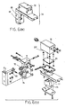
- Figure 4 is a perspective view of the integrable valve and position control device 56, according to the present invention, assembled together with the clamp 57 as a single unit 94.
- Figures 5(a)-5(e) include detailed cross-sectional views of the integrable valve and position control system 56 illustrated in Figure 4.
- Figure 5(a) is a cross-sectional front view of the valve and position system 56 omitting a tie plate 95 and fastening rod 96.
- Figure 5(b) is a cross-sectional side view of the valve and position system 56 along the lines 5(b)-5(b) in Figure 5(a).
- Figure 5(c) is a cross-sectional side view of the valve and position system 56 along the lines 5(c)-5(c) in Figure 5(a).
- Figures 5(d)(1) and 5(d)(2) is a cross-sectional bottom view of the integrable valve and position control device 56 including the tie plate 95 and fastening rod 96.
- a first aperture 102 and a second aperture 104 permit pneumatic communication between the integrable valve and position control device system 56 and the clamp 57 when the system 56 and the clamp 57 are fastened or assembled together.
- Figure 5(e) is a cross-sectional view of the tie plate 95 in Figure 5(d)(2).
- Figure 5 (along with Figure 6) demonstrates the detachability of the various housings and compartments of the present invention. Such detachability is desirable, for such enables the integrable valve and position control system 56 and the clamp 57 to easily integrated and additionally enables servicing and/or replacement of the various components and modules which comprise the present invention.
- Figure 6(a) is a perspective view of the integrable valve and position control system 56 within the complementary housing 54.
- Figure 6(b) is an exploded view of the integrable valve and position control system 56.
- This particular embodiment of the present invention is slightly different in that the electronic control circuit 84, the first solenoid direction control valve 72, and the second solenoid direction control valve 74 are generally housed within an electrical compartment 100 separate from the first direction control valve 32 and the second direction control valve 34, all within the complementary housing 54.
- the electrical compartment 100 is generally defined by a cover piece 98.
- FIG. 7 is a block diagram of a clamp network system 106 in accordance with the present invention.
- the clamp network system 106 includes a plurality of clamps 57a, 57b, and 57c having clamp arms 80a, 80b, and 80c respectively, actuated in response to pressurized air.
- each clamp 57a, 57b, and 57c is in communication with a source of air pressure 108.
- an integrable valve and control position system 56a, 56b, and 56c is associated with each clamp 57a, 57b, and 57c respectively.
- Each valve and control position system 56a, 56b, and 56c is in communication with a power source 110.
- each valve and control position system 56a, 56b, and 56c respectively may also be in communication with an external computer network 112 via the electronic interface port 82a, 82b, and 82c respectively.
- an actuator typically a piston and a rod
- the stroking of the actuator drives a clamp arm between a clamped position and a released position.
- Such known systems typically monitor or sense the position of the actuator only at the first and second end limits of travel.
- the typical valve and cylinder system 8 illustrated in Figure 2 senses the position of the piston 62 only at the first and second end limits of travel 14 and 16 with proximity sensors 18. In this manner, the clamped position is associated with one end limit of travel and the released position is associated with the opposite end limit of travel.
- the clamp arm in known valve and cylinder systems has predetermined clamped and released positions.
- the present invention includes means for selectively setting at least one of the clamped position and the released position at an actuator position between the first and second end limits of travel of the actuator.
- the present invention further includes means for sensing the position of the clamp arm 80, actuator 62, and/or the shaft 78 operably connecting the actuator 62 and the clamp arm 80 as well as means for controlling the movement of the actuator 62.
- the present invention includes means for sensing the position of the clamp arm 80 such as a rotary position sensor, means for sensing the position of the actuator 62 such as an absolute linear position sensor, and/or means for sensing the position of the shaft 78 such as a rotary position sensor.
- the actuator 62 is moved in response to differential air pressure in first and second chambers 58 and 22 located on opposite sides of the actuator 62.
- the present invention includes means for adjusting the air pressure in the first and second chambers 58 and 22.
- the present invention includes means for sensing air pressure in the first and second chambers 58 and 22, means for supplying pressurized air to the first and second chambers 58 and 22, and means for exhausting pressurized air from the first and second chambers 58 and 22.
- the electronic control circuit 84 can be programmed to select the clamped and release positions for each specific application of the clamp 57. Selecting an application specific clamped and/or released position decreases the cycle time of the clamp 57 and, thus, increases operation throughput.
- the operation of a first clamp can interfere with the operation of a second clamp and, thus, the first clamp needs to be opened or closed before the second clamp is operated.
- the electronic control circuit 84 can determine when the first clamp has cleared the path of the second clamp and activate the second clamp before the first clamp reaches either the clamped or released position.
- the electronic control circuit 84 includes means for calculating the speed of actuator movement. Using the position sensing means, the means for controlling the movement of the actuator 62, and such actuator speed calculation means, the electronic control circuit 84 can be programmed to selectively control the speed of actuator movement as the actuator 62 moves between the first and second end limits of travel. Preferably, the electronic control circuit 84 can be programmed to selectively control the speed of actuator movement as the actuator 62 approaches at least one of the first and second end limits of travel to provide a soft touch clamp action.
- each pair of air lines connecting each clamp to the single valve may have a different length and/or a different route (or, in other words, each pair of air lines may have a different number of bends and/or vertical displacements along the length of the air line). Accordingly, the time it takes for pressurized air to reach each clamp varies. As a result, substantial adjustment or tweaking of each clamp is necessary to operate (i.e. open and close) all the clamps either simultaneously or in a predetermined sequence.
- the electronic control circuit 84 can be programmed to precisely operate the respective clamp 57 and eliminate such concerns.
- the present invention eliminates many, if not all, of the drawbacks and prior art problems associated with the cylinder and the air valve system being remotely located from each other.
- the present invention does so by making the air valve system integrable with the cylinder associated with the clamp 57.
Abstract
Description
- The present invention relates to industrial clamps having at least one pivotal arm.
- Figure 1 is a perspective view of a typical valve and
cylinder system 8 which is common in the art of industrial clamps. In particular, there is ahollow cylinder 10 having afirst end 14 and asecond end 16. Within thecylinder 10, there is a piston (not shown) which is movable between a first end position and a second end position. The piston is connected to arod 12 that protrudes through thesecond end 16. Therod 12 is typically connected to a linkage assembly (not shown) to which a shaft (not shown) is rotatably connected. A clamp arm (not shown) is then typically fixedly mounted on the shaft. - At or near both the
first end 14 and thesecond end 16 of thecylinder 10 are twoproximity switches 18. These twoproximity switches 18 serve to provide an indirect indication of the rotational position of the clamp arm by detecting whether the piston (or rod 12) is at the first end position (retracted position) or the second end position (extended position). Typically, thecylinder 10, in combination with theproximity switches 18, requires one or more electrical power and/orcontrol cables 19. - The
rod 12 and the piston (not shown) together define a full bore area (not shown) and an annulus area (not shown) on opposite sides of the piston within thecylinder 10. From the full bore and annulus two areas within thecylinder 10, afirst air line 20 and asecond air line 22 are routed to anair valve system 24 which is located remote from thecylinder 10. - The
air valve system 24 typically has one or more exhaust ports in which one ormore silencers 26 are fitted. In addition, theair valve system 24 typically has a main pneumaticair supply line 28 and an electrical power and/orcontrol cable 30. - The typical valve and
cylinder system 8, as described above, has certain drawbacks. First, for example, the remote location of theair valve system 24 from thecylinder 10 can create undesired difficulties if local control of thecylinder 10 and the associated clamp arm is desired. Second, the remote location of theair valve system 24 from thecylinder 10 also, in many instances, unnecessarily dictates the combined need for a multiplicity of electrical power and/or control cables and air lines at the two separate locations. The unnecessary multiplicity of electrical power and/or control cables can be especially troublesome in a manufacturing environment wherein many clamps are used simultaneously. Third, the remote location of theair valve system 24 from thecylinder 10 also unnecessarily creates additional problems for the combined servicing and repair of thecylinder 10 and theair valve system 24 at the two separate locations. Fourth, the remote location of theair valve system 24 from thecylinder 10 uses only approximately 20% of the compressed air in thesystem 8. - Thus, there is a present need in the art for eliminating the drawbacks and problems associated with the cylinder and the air valve system being at locations which are remote from each other.
- In a clamp having at least one clamp arm moveable between a clamped position and a released position in response to movement of an actuator between first and second end limits of travel, the present invention provides means for selectively setting at least one of the clamped position and the released position at an actuator position between the first and second end limits of travel of the actuator.
- In a clamp having at least one clamp arm moveable between a clamped position and a released position in response to movement of an actuator between first and second end limits of travel, the present invention provides means for selectively controlling a speed of actuator movement as the actuator moves between the first and second end limits of travel. Preferably, the present invention further provides means for selectively controlling the speed of actuator movement as the actuator approaches at least one of the first and second end limits of travel to provide a soft touch clamp action.
- In a clamp having at least one clamp arm moveable between a clamped position and a released position in response to movement of an actuator controlled by differential fluid pressure in first and second chambers located on opposite sides of the actuator, the present invention provides means for selectively adjusting pressurized fluid within the first and second chambers independent of one another.
- In a clamp network system having a plurality of clamps actuated in response to pressurized fluid, the present invention provides each of the plurality of clamps with a separate valve and position control system.
- The present invention also provides a valve and position control system which is integrable with an industrial clamp. The valve and position control system, according to the present invention, is integrable with a clamp which has a main housing, a hollow cylinder having a first end and a second end mounted within the main housing, and a piston movable between a first end position and a second end position within the hollow cylinder. The clamp further includes a rod connected to the piston and protruding from the second end of the hollow cylinder, defining a full bore area and an annulus area on opposite sides of the piston within the hollow cylinder. In addition, the clamp includes a linkage assembly coupled to the rod and mounted within the main housing, a shaft rotatably connected to the linkage assembly, a clamp arm fixedly mounted on the shaft outside of the main housing, means for sensing the position of the clamp arm, and means for sensing the air pressure within the hollow cylinder. The valve and position control system, according to the basic embodiment of the present invention, is intended to be integrable with this type of clamp.
- In a basic embodiment of the present invention, the integrable valve and position control system includes a complementary housing which is integrable with the main housing of the clamp. This complementary housing has an air supply port, an exhaust port, and an electronic interface port. In addition, the integrable valve and position control system includes a first direction control valve having three ports and two positions. This first direction control valve is capable of selectively and pneumatically connecting the full bore area of the hollow cylinder to one of either the air supply port or the exhaust port. The first direction control valve is mounted within the complementary housing. In addition to the first direction control valve, the integrable valve and position control system also includes a second direction control valve having three ports and two positions. This second direction control valve is capable of selectively and pneumatically connecting the annulus area of the hollow cylinder to one of either the air supply port or the exhaust port. The second direction control valve is mounted within the complementary housing.
- According to the basic embodiment of the present invention, the integrable valve and position control system also includes first means for pneumatically piloting the first direction control valve. This first pneumatic piloting means is mounted within the complementary housing. In addition to the first pneumatic piloting means, the integrable valve and position control system also includes second means for pneumatically piloting the second direction control valve. This second pneumatic piloting means is also mounted within the complementary housing.
- Further according to the basic embodiment of the present invention, the integrable valve and position control system also includes an electronic control circuit mounted within the complementary housing. This electronic control circuit is electrically connected to the first pneumatic piloting means, the second pneumatic piloting means, and the electronic interface port. In addition, this electronic control circuit is also electrically connectible to the clamp arm position sensing means and to the air pressure sensing means.
- According to the basic embodiment of the present invention, the first pneumatic piloting means preferably includes a first solenoid direction control valve having three ports and two positions. This first solenoid direction control valve selectively and pneumatically connects the first direction control valve to one of either the air supply port or the exhaust port to pilot the first direction control valve. In addition, the second pneumatic piloting means preferably includes a second solenoid direction control valve having three ports and two positions. This second solenoid direction control valve selectively and pneumatically connects the second direction control valve to one of either the air supply port or the exhaust port to pilot the second direction control valve. In this way, the first direction control valve and the second direction control valve are each piloted independently.
- Further according to the basic embodiment of the present invention, the integrable valve and position control system also preferably includes means for metering out air from the hollow cylinder. This metering out means is mounted within the complementary housing and preferably includes first means for metering out air from the full bore area of the hollow cylinder and into the first direction control valve, and preferably includes second means for metering out air from the annulus area of the hollow cylinder and into the second direction control valve. The first metering out means preferably includes a first flow control valve and a first non-return check valve pneumatically connected in parallel, and the second metering out means preferably includes a second flow control valve and a second non-return check valve pneumatically connected in parallel.
- Still further according to the basic embodiment of the present invention, the complementary housing preferably includes a plurality of compartments, wherein the electronic control circuit is situated in one of the compartments, and wherein the first directional control valve and the second directional control valve are situated in another one of the compartments. Preferably, at least some of the compartments are detachable from at least one of the main housing and the complementary housing.
- Finally according to the basic embodiment of the present invention, the integrable valve and position control system also preferably includes a silencer fitted within the exhaust port of the complementary housing, a first exhaust restrictor pneumatically connected between the first direction control valve and the exhaust port, a second exhaust restrictor pneumatically connected between the second direction control valve and the exhaust port, first means for manually overriding the position of the first direction control valve, and second means for manually overriding the position of the second direction control valve.
- In an alternative embodiment of the present invention, the integrable valve and position control system accommodates a clamp which includes neither clamp arm position sensing means nor air pressure sensing means. To be integrable with this type of clamp, according to the alternative embodiment of the present invention, the integrable valve and position control system includes a complementary housing which is integrable with the main housing of the clamp. This complementary housing has an air supply port, an exhaust port, and an electronic interface port. In addition, the integrable valve and position control system includes means for sensing the position of the clamp arm, means for sensing the air pressure within the hollow cylinder, and a first direction control valve having three ports and two positions. This first direction control valve is capable of selectively and pneumatically connecting the full bore area of the hollow cylinder to one of either the air supply port or the exhaust port. The first direction control valve is mounted within the complementary housing. In addition to the first direction control valve, the integrable valve and position control system also includes a second direction control valve having three ports and two positions. This second direction control valve is capable of selectively and pneumatically connecting the annulus area of the hollow cylinder to one of either the air supply port or the exhaust port. The second direction control valve is mounted within the complementary housing.
- According to the alternative embodiment of the present invention, the integrable valve and position control system also includes first means for pneumatically piloting the first direction control valve. This first pneumatic piloting means is mounted within the complementary housing. In addition to the first pneumatic piloting means, the integrable valve and position control system also includes second means for pneumatically piloting the second direction control valve. This second pneumatic piloting means is also mounted within the complementary housing.
- Further according to the alternative embodiment of the present invention, the integrable valve and position control system also includes an electronic control circuit mounted within the complementary housing. This electronic control circuit is electrically connected to the first pneumatic piloting means, the second pneumatic piloting means, the electronic interface port, the clamp arm position sensing means, and the air pressure sensing means.
- According to the alternative embodiment of the present invention, the first pneumatic piloting means preferably includes a first solenoid direction control valve having three ports and two positions. This first solenoid direction control valve selectively and pneumatically connects the first direction control valve to one of either the air supply port or the exhaust port to pilot the first direction control valve. In addition, the second pneumatic piloting means preferably includes a second solenoid direction control valve having three ports and two positions. This second solenoid direction control valve selectively and pneumatically connects the second direction control valve to one of either the air supply port or the exhaust port to thereby pilot the second direction control valve. In this way, the first direction control valve and the second direction control valve are each piloted independently.
- Further according to the alternative embodiment of the present invention, the integrable valve and position control system also preferably includes means for metering out air from the hollow cylinder. This metering out means is mounted within the complementary housing and preferably includes first means for metering out air from the full bore area of the hollow cylinder and into the first direction control valve, and preferably includes second means for metering out air from the annulus area of the hollow cylinder and into the second direction control valve. The first metering out means preferably includes a first flow control valve and a first non-return check valve pneumatically connected in parallel, and the second metering out means preferably includes a second flow control valve and a second non-return check valve pneumatically connected in parallel.
- Still further according to the alternative embodiment of the present invention, the complementary housing preferably includes a plurality of compartments, wherein the electronic control circuit is situated in one of the compartments, and wherein the first directional control valve and the second directional control valve are situated in another one of the compartments. Preferably, at least some of the compartments are detachable from at least one of the main housing and the complementary housing.
- Finally according to the alternative embodiment of the present invention, the integrable valve and position control system also preferably includes a silencer fitted within the exhaust port of the complementary housing, a first exhaust restrictor pneumatically connected between the first direction control valve and the exhaust port, a second exhaust restrictor pneumatically connected between the second direction control valve and the exhaust port, first means for manually overriding the position of the first direction control valve, and second means for manually overriding the position of the second direction control valve. In addition, the clamp arm sensing means preferably includes either proximity switches, at least one rotary switch, or at least one absolute position linear sensor.
- In an another embodiment of the present invention, the clamp is actually integrated with the valve and position control system to form a clamp with integrated valve and position control system. In such an another embodiment, the clamp includes an integrated housing having an air supply port, an exhaust port, and an electronic interface port. The clamp also includes a hollow cylinder having a first end and a second end mounted within the integrated housing, a piston movable between a first end position and a second end position within the hollow cylinder. The clamp further includes a rod connected to the piston and protruding from the second end of the hollow cylinder, defining a full bore area and an annulus area on opposite sides of the piston within the hollow cylinder. In addition, the clamp includes a linkage assembly coupled to the rod and mounted within the integrated housing, a shaft rotatably connected to the linkage assembly, a clamp arm fixedly mounted on the shaft outside of the integrated housing, means for sensing the position of the clamp arm, and means for sensing the air pressure within the hollow cylinder.
- According to the another embodiment of the present invention, the clamp also includes a first direction control valve having three ports and two positions. This first direction control valve selectively and pneumatically connects the full bore area of the hollow cylinder to one of either the air supply port or the exhaust port. The first direction control valve is mounted within the integrated housing. In addition to the first direction control valve, the clamp also includes a second direction control valve having three ports and two positions. This second direction control valve selectively and pneumatically connects the annulus area of the hollow cylinder to one of either the air supply port or the exhaust port. The second direction control valve is mounted within the integrated housing.
- Further according to the another embodiment of the present invention, the clamp also includes first means for pneumatically piloting the first direction control valve. This first pneumatic piloting means is mounted within the integrated housing. In addition to the first pneumatic piloting means, the clamp also includes second means for pneumatically piloting the second direction control valve. This second pneumatic piloting means is also mounted within the integrated housing. Further, the clamp also includes an electronic control circuit mounted within the integrated housing. This electronic control circuit is electrically connected to the first pneumatic piloting means, the second pneumatic piloting means, the electronic interface port, the clamp arm position sensing means, and the air pressure sensing means.
- According to the another embodiment of the present invention, the first pneumatic piloting means preferably includes a first solenoid direction control valve having three ports and two positions. This first solenoid direction control valve selectively and pneumatically connects the first direction control valve to one of either the air supply port or the exhaust port to pilot the first direction control valve. In addition, the second pneumatic piloting means preferably includes a second solenoid direction control valve having three ports and two positions. This second solenoid direction control valve selectively and pneumatically connects the second direction control valve to one of either the air supply port or the exhaust port to pilot the second direction control valve. In this way, the first direction control valve and the second direction control valve are each piloted independently.
- Further according to the another embodiment of the present invention, the clamp also preferably includes means for metering out air from the hollow cylinder. This metering out means is mounted within the integrated housing and preferably includes first means for metering out air from the full bore area of the hollow cylinder and into the first direction control valve, and preferably includes second means for metering out air from the annulus area of the hollow cylinder and into the second direction control valve. The first metering out means preferably includes a first flow control valve and a first non-return check valve pneumatically connected in parallel, and the second metering out means preferably includes a second flow control valve and a second non-return check valve pneumatically connected in parallel.
- Still further according to the another embodiment of the present invention, the integrated housing preferably includes a plurality of compartments, wherein the electronic control circuit, the hollow cylinder, and the first directional control valve and the second directional control valve are situated in separate compartments. Preferably, at least some of the compartments are detachable from the integrated housing.
- Finally according to the another embodiment of the present invention, the clamp also preferably includes a silencer fitted within the exhaust port of the integrated housing, a first exhaust restrictor pneumatically connected between the first direction control valve and the exhaust port, a second exhaust restrictor pneumatically connected between the second direction control valve and the exhaust port, first means for manually overriding the position of the first direction control valve, and second means for manually overriding the position of the second direction control valve. In addition, the clamp arm sensing means preferably includes either proximity switches, at least one rotary switch, or at least one absolute position linear sensor.
- Other objects, advantages and applications of the present invention will become apparent to those skilled in the art when the following description of the best mode contemplated for practicing the invention is read in conjunction with the accompanying drawings.
- The description herein makes reference to the accompanying drawings wherein like reference numerals refer to like parts throughout the several views, and wherein:
- Figure 1 is a perspective view of a typical valve and cylinder system which is common in the art of industrial clamps;
- Figure 2 is a pneumatic flow diagram representing, according to a basic embodiment of the present invention, a part of an integrable valve and position control system as such relates to a clamp;
- Figure 3 is a block diagram illustrating how the electronic control circuit, according to the present invention, electronically communicates with the various electrical sensor and control components of the integrable valve and position control device and/or of the clamp;
- Figure 4 is a perspective view of the integrable valve and
position control device 56, according to the present invention, assembled together with theclamp 57 as asingle unit 94; - Figures 5(a)-5(e) include detailed cross-sectional views of the integrable valve and position control system illustrated in Figure 4;
- Figure 6(a) is a perspective view of the integrable valve and position control system within a complementary housing;
- Figure 6(b) is an exploded view of the integrable valve and position control system of Figure 6(a); and
- Figure 7 is a block diagram of a clamp network system in accordance with the present invention.
-
- The preferred structures and embodiments of the integrable valve and position control system for a clamp, according to the present invention, are set forth hereinbelow. The term "integrable" as used herein means (1) that the valve and position control system may be integrated into a clamp, or (2) that the valve and position control system may be packaged with a clamp in a single piece housing, or (3) that the valve and position control system may be packaged in a separate or complementary housing which is assembled with or fastened to the clamp housing to form a single unit. As such, in a clamp network system having a plurality of clamps, each clamp has a separate valve and position control system which is located adjacent to the respective clamp.
- Figure 2 is a pneumatic flow diagram representing, according to a basic embodiment of the present invention, a part of an integrable valve and
position control system 56 as such relates to a clamp 57 (see also Figure 4). In Figure 2, therein is ahollow cylinder 60 having afirst end 64 and asecond end 66 mounted within amain housing 70 of a clamp. Apiston 62 is movable between a first end position approximately adjacent to thefirst end 64 and a second end position approximately adjacent to thesecond end 66 within thehollow cylinder 60. Arod 68 is connected to thepiston 62 and protrudes from thesecond end 66 of thehollow cylinder 60, defining a first chamber orfull bore area 58 and a second chamber orannulus area 22 on opposite sides of thepiston 62 within thehollow cylinder 60. Thefull bore area 58 is commonly referred to as a blind end and theannulus area 22 is commonly referred to as a rod end. - Within the
main housing 70, a linkage assembly (not shown) is coupled to therod 68, and a shaft 78 (see Figure 4) is rotatably connected to the linkage assembly. A clamp arm 80 (see Figure 4) is fixedly mounted on theshaft 78 outside of themain housing 70. Mounted to themain housing 70 is means for sensing the position of the clamp arm 80 (see Figure 3) and means for sensing the air pressure within the hollow cylinder 60 (see Figure 3). The clamp arm position sensing means preferably includes either proximity switches (similar to those depicted in Figure 1), at least one rotary switch, or at least one absolute position linear sensor. For example, the "Clamp Arm Position Sensing Apparatus" according to United States Patent Number 5,875,417, by M.J. Golden, which is incorporated herein by reference in its entirety, can be utilized as the clamp arm position sensing means for purposes of the present invention. The valve andposition control system 56, according to this basic embodiment of the present invention, is integrable with the above-describedclamp 57. - In the basic embodiment of the present invention, the integrable valve and
position control system 56 includes acomplementary housing 54 which is integrable with themain housing 70 of the clamp. Thecomplementary housing 54 has anair supply port 76, anexhaust port 38, and an electronic interface port or I/O (input/output) port 82 (see Figure 3). In addition, the integrable valve andposition control system 56 includes a firstdirection control valve 32 having three ports and two positions. The firstdirection control valve 32 is capable of selectively and pneumatically connecting thefull bore area 58 of thehollow cylinder 60 to one of either theair supply port 76 or theexhaust port 38. The firstdirection control valve 32 is mounted within thecomplementary housing 54. The integrable valve andposition control system 56 also includes a seconddirection control valve 34 having three ports and two positions. The seconddirection control valve 34 is capable of selectively and pneumatically connecting theannulus area 22 of thehollow cylinder 60 to one of either theair supply port 76 or theexhaust port 38. The seconddirection control valve 34 is also mounted within thecomplementary housing 54. - According to the basic embodiment of the present invention, the integrable valve and
position control system 56 further includes first means for pneumatically piloting the firstdirection control valve 32. The first pneumatic piloting means is mounted within thecomplementary housing 54. The integrable valve andposition control system 56 also includes second means for pneumatically piloting the seconddirection control valve 34. The second pneumatic piloting means is also mounted within thecomplementary housing 54. - Further according to the basic embodiment of the present invention, the integrable valve and
position control system 56 also includes an electronic control circuit 84 (see Figure 3) mounted within thecomplementary housing 54. Theelectronic control circuit 84 is electrically connected to the first pneumatic piloting means, the second pneumatic piloting means, and the electronic interface port 82 (see Figure 3). In addition, theelectronic control circuit 84 is also electrically connectible to the clamp arm position sensing means (see Figure 3) and to the air pressure sensing means (see Figure 3). - According to the basic embodiment of the present invention, the first pneumatic piloting means preferably includes a first solenoid
direction control valve 72 having three ports and two positions. The first solenoiddirection control valve 72 selectively and pneumatically connects the firstdirection control valve 32 to one of either theair supply port 76 or theexhaust port 38 to pilot the firstdirection control valve 32. In addition, the second pneumatic piloting means preferably includes a second solenoiddirection control valve 74 having three ports and two positions. The second solenoiddirection control valve 74 selectively and pneumatically connects the seconddirection control valve 34 to one of either theair supply port 76 or theexhaust port 38 to pilot the seconddirection control valve 34. In this way, the firstdirection control valve 32 and the seconddirection control valve 34 are each piloted independently. - Further according to the basic embodiment of the present invention, the integrable valve and
position control system 56 also preferably includes means for metering out air from thehollow cylinder 60. This metering out means is mounted within thecomplementary housing 54 and preferably includes first means for metering out air from thefull bore area 58 of thehollow cylinder 60 and into the firstdirection control valve 32, and preferably includes second means for metering out air from theannulus area 22 of thehollow cylinder 60 and into the seconddirection control valve 34. The first metering out means preferably includes a firstflow control valve 48 and a firstnon-return check valve 46 pneumatically connected in parallel, and the second metering out means preferably includes a secondflow control valve 52 and a secondnon-return check valve 50 pneumatically connected in parallel. Preferably, both the firstflow control valve 48 and the secondflow control valve 52 are manually adjustable. - Still further according to the basic embodiment of the present invention, the
complementary housing 54 preferably includes a plurality of compartments (see Figure 5 and Figure 6), wherein the electronic control circuit 84 (see Figure 3 and Figure 6) is situated in one of the compartments, and wherein the firstdirection control valve 32 and the seconddirection control valve 34 are situated in another one of the compartments. Preferably, at least some of the compartments are detachable from at least one of themain housing 70 and the complementary housing 54 (see Figure 4, Figure 5, and Figure 6). - Finally according to the basic embodiment of the present invention, the integrable valve and
position control system 56 also preferably includes asilencer 40 fitted within theexhaust port 38 of thecomplementary housing 54, afirst exhaust restrictor 42 pneumatically connected between the firstdirection control valve 32 and theexhaust port 38, asecond exhaust restrictor 44 pneumatically connected between the seconddirection control valve 34 and theexhaust port 38, first means for manually overriding the position of the firstdirection control valve 32, and second means for manually overriding the position of the seconddirection control valve 34. Preferably, the first manual override means is a manually pressable first button 86 (see Figure 4 and Figure 5). Also, the second manual override means is preferably a manually pressable second button 88 (see Figure 4 and Figure 5). - In an alternative embodiment of the present invention, the integrable valve and
position control system 56 accommodates aclamp 57 which includes neither clamp arm position sensing means nor air pressure sensing means. To be integrable with this type ofclamp 57, according to the alternative embodiment of the present invention, the integrable valve andposition control system 56 alternately includes a clamp arm position sensor 90 (see Figure 3) and an air pressure sensor 92 (see Figure 3) along with the features included in the above-described basic embodiment. This clamparm position sensor 90 preferably includes either proximity switches (similar to those depicted in Figure 1), at least one rotary switch, or at least one absolute position linear sensor. For example, the "Clamp Arm Position Sensing Apparatus" according to United States Patent Number 5,875,417, by M.J. Golden, which is incorporated herein by reference in its entirety, can be utilized as the clamparm position sensor 90 for purposes of the present invention. - In an another embodiment of the present invention, the
clamp 57 is actually assembled to the valve andposition control system 56. In such an another embodiment, themain housing 70 and thecomplementary housing 54 of the previously discussed embodiments of the present invention are fastened together to form a single unit 94 (see Figure 4). - Figure 3 is a block diagram illustrating how the
electronic control circuit 84, according to the present invention, electronically communicates with the various electrical sensor and control components of the integrable valve andposition control device 56 and/or theclamp 57. In particular, theelectronic control circuit 84 receives data from the clamparm position sensor 90 and theair pressure sensor 92 to enable theelectronic control circuit 84 to determine the position of the clamp arm 80 (see Figure 4). Theelectronic control circuit 84 can process and respond to the received data by sending appropriate electronic control signals to the first solenoiddirection control valve 72 and to the second solenoiddirection control valve 74. In this way, theelectronic control circuit 84 can selectively activate and utilize the first solenoiddirection control valve 72 and/or the second solenoiddirection control valve 74 to pilot the firstdirection control valve 32 and the seconddirection control valve 34 independently. As a result, the air pressure within thefull bore area 58 and theannulus area 22 of thehollow cylinder 60 can be selectively and independently controlled to control the extension and retraction of therod 68 as thepiston 62 moves between its first end position and its second end position within thehollow cylinder 60. As therod 68 extends and retracts, the position of theclamp arm 80 is manipulated and controlled. Furthermore, theelectronic control circuit 84 can electronically communicate to an external computer network 112 (see Figure 7) via theelectronic interface port 82. - Figure 4 is a perspective view of the integrable valve and
position control device 56, according to the present invention, assembled together with theclamp 57 as asingle unit 94. - Figures 5(a)-5(e) include detailed cross-sectional views of the integrable valve and
position control system 56 illustrated in Figure 4. Figure 5(a) is a cross-sectional front view of the valve andposition system 56 omitting atie plate 95 andfastening rod 96. Figure 5(b) is a cross-sectional side view of the valve andposition system 56 along the lines 5(b)-5(b) in Figure 5(a). Figure 5(c) is a cross-sectional side view of the valve andposition system 56 along the lines 5(c)-5(c) in Figure 5(a). Figures 5(d)(1) and 5(d)(2) is a cross-sectional bottom view of the integrable valve andposition control device 56 including thetie plate 95 andfastening rod 96. As best illustrated in Figure 5(d)(1) and 5(d)(2), afirst aperture 102 and asecond aperture 104 permit pneumatic communication between the integrable valve and positioncontrol device system 56 and theclamp 57 when thesystem 56 and theclamp 57 are fastened or assembled together. Figure 5(e) is a cross-sectional view of thetie plate 95 in Figure 5(d)(2). As illustrated, Figure 5 (along with Figure 6) demonstrates the detachability of the various housings and compartments of the present invention. Such detachability is desirable, for such enables the integrable valve andposition control system 56 and theclamp 57 to easily integrated and additionally enables servicing and/or replacement of the various components and modules which comprise the present invention. - Figure 6(a) is a perspective view of the integrable valve and
position control system 56 within thecomplementary housing 54. Figure 6(b) is an exploded view of the integrable valve andposition control system 56. This particular embodiment of the present invention is slightly different in that theelectronic control circuit 84, the first solenoiddirection control valve 72, and the second solenoiddirection control valve 74 are generally housed within anelectrical compartment 100 separate from the firstdirection control valve 32 and the seconddirection control valve 34, all within thecomplementary housing 54. Theelectrical compartment 100 is generally defined by acover piece 98. - Figure 7 is a block diagram of a
clamp network system 106 in accordance with the present invention.
Theclamp network system 106 includes a plurality ofclamps clamp arms clamp air pressure 108. In accordance with the present invention, an integrable valve andcontrol position system clamp control position system power source 110. Theelectronic control circuit 84a, 84b, and 84c of each valve andcontrol position system external computer network 112 via theelectronic interface port - In known valve and cylinder systems, an actuator, typically a piston and a rod, is moved or stroked between first and second end limits of travel within a cylinder. The stroking of the actuator drives a clamp arm between a clamped position and a released position. Such known systems typically monitor or sense the position of the actuator only at the first and second end limits of travel. For example, the typical valve and
cylinder system 8, illustrated in Figure 2, senses the position of thepiston 62 only at the first and second end limits oftravel proximity sensors 18. In this manner, the clamped position is associated with one end limit of travel and the released position is associated with the opposite end limit of travel. As a result, the clamp arm in known valve and cylinder systems has predetermined clamped and released positions. - Unlike the prior art, the present invention includes means for selectively setting at least one of the clamped position and the released position at an actuator position between the first and second end limits of travel of the actuator. To selectively set the clamped and/or released positions, the present invention further includes means for sensing the position of the
clamp arm 80,actuator 62, and/or theshaft 78 operably connecting theactuator 62 and theclamp arm 80 as well as means for controlling the movement of theactuator 62. The present invention includes means for sensing the position of theclamp arm 80 such as a rotary position sensor, means for sensing the position of theactuator 62 such as an absolute linear position sensor, and/or means for sensing the position of theshaft 78 such as a rotary position sensor. - Within the present invention, the
actuator 62 is moved in response to differential air pressure in first andsecond chambers actuator 62. Thus, to control the movement of theactuator 62, the present invention includes means for adjusting the air pressure in the first andsecond chambers - To adjust the air pressure in the first and
second chambers second chambers second chambers second chambers - Using the means for sensing the position of the
clamp arm 80,actuator 62, and/orshaft 78 as well as means for controlling the movement of theactuator 62, theelectronic control circuit 84 can be programmed to select the clamped and release positions for each specific application of theclamp 57. Selecting an application specific clamped and/or released position decreases the cycle time of theclamp 57 and, thus, increases operation throughput. - In some known clamp network system applications the operation of a first clamp can interfere with the operation of a second clamp and, thus, the first clamp needs to be opened or closed before the second clamp is operated. Using the position sensing means, the
electronic control circuit 84 can determine when the first clamp has cleared the path of the second clamp and activate the second clamp before the first clamp reaches either the clamped or released position. - Within the present invention, the
electronic control circuit 84 includes means for calculating the speed of actuator movement. Using the position sensing means, the means for controlling the movement of theactuator 62, and such actuator speed calculation means, theelectronic control circuit 84 can be programmed to selectively control the speed of actuator movement as theactuator 62 moves between the first and second end limits of travel. Preferably, theelectronic control circuit 84 can be programmed to selectively control the speed of actuator movement as the actuator 62 approaches at least one of the first and second end limits of travel to provide a soft touch clamp action. - In some prior art systems, one valve is used to control two or more clamps at different remote locations. In this type of prior art valve and cylinder system, each pair of air lines connecting each clamp to the single valve may have a different length and/or a different route (or, in other words, each pair of air lines may have a different number of bends and/or vertical displacements along the length of the air line). Accordingly, the time it takes for pressurized air to reach each clamp varies. As a result, substantial adjustment or tweaking of each clamp is necessary to operate (i.e. open and close) all the clamps either simultaneously or in a predetermined sequence. By locating the valve and
position control system 54 adjacent to therespective clamp 57, theelectronic control circuit 84 can be programmed to precisely operate therespective clamp 57 and eliminate such concerns. - In light of the above, the present invention eliminates many, if not all, of the drawbacks and prior art problems associated with the cylinder and the air valve system being remotely located from each other. The present invention does so by making the air valve system integrable with the cylinder associated with the
clamp 57. - While the invention has been described in connection with what is presently considered to be the most practical and preferred embodiment, it is to be understood that the invention is not to be limited to the disclosed embodiments but, on the contrary, is intended to cover various modifications and equivalent arrangements included within the spirit and scope of the appended claims, which scope is to be accorded the broadest interpretation so as to encompass all such modifications and equivalent structures as is permitted under the law.
Claims (39)
- A clamp having at least one clamp arm moveable between a clamped position and a released position in response to movement of an actuator between first and second end limits of travel, the improvement comprising:
means for selectively setting at least one of the clamped position and the released position at an actuator position between the first and second end limits of travel of the actuator. - A clamp according to claim 1 further comprising sensing means for sensing a position of one of the clamp arm and the actuator.
- A clamp according to claim 2 wherein the sensing means comprises a rotary position sensor.
- A clamp according to claim 2 or claim 3 wherein sensing the means comprises an absolute linear position sensor.
- A clamp according to any one of claims 2 to 4 further comprising a rotary shaft operably connecting the actuator and the clamp arm, the sensing means sensing a position of the shaft.
- A clamp according to any one of claims 1 to 5 further comprising controlling means for controlling the movement of the actuator.
- A clamp according to claim 6 wherein the actuator is moveable in response to differential fluid pressure in first and second chambers located on opposite sides of the actuator and the controlling means includes means for adjusting fluid pressure in the first and second chambers.
- A clamp according to claim 7 wherein the means for adjusting said fluid pressure further comprises means for sensing fluid pressure in the first and second chambers.
- A clamp according to claim 7 or claim 8 wherein the means for adjusting said fluid pressure further comprises a source of pressurized fluid and control valve means for selectively communicating one of the first and second chambers with the source of pressurized fluid and for selectively exhausting pressurized fluid from the other the first and second chambers.
- A clamp as claimed in any one of claims 1 to 9 further comprising means for sensing a position of one of the clamp arm and the actuator and means for controlling the movement of the actuator.
- A clamp according to any one of claims 1 to 10 further comprising means for selectively controlling the speed of actuator movement as the actuator moves between the first and second end limits of travel.
- A clamp having at least one clamp arm moveable between a clamped position and a released position in response to movement of an actuator between first and second end limits of travel, the improvement comprising:
means for selectively controlling the speed of actuator movement as the actuator moves between the first and second end limits of travel. - A clamp according to claim 12 further comprising means for selectively controlling the speed of actuator movement as the actuator approaches at least one of the first and second end limits of travel to provide a soft touch clamp action.
- A clamp according to claim 12 or claim 13 further comprising sensing means for sensing a position of one of the clamp arm and the actuator.
- A clamp according to claim 14 wherein the sensing means comprises a rotary position sensor.
- A clamp according to claim 14 or claim 15 wherein the sensing means comprises an absolute linear position sensor.
- A clamp according to any one of claims 14 to 16 further comprising a rotary shaft operably connecting the actuator and the clamp arm, the sensing means sensing a position of the shaft.
- A clamp according to any one of claims 12 to 17 further comprising means for calculating the speed of the actuator movement.
- A clamp according to any one of claims 12 to 18 further comprising controlling means for controlling the movement of the actuator.
- A clamp according to claim 19 wherein the actuator is moveable in response to differential fluid pressure in first and second chambers located on opposite sides of the actuator, and the controlling means includes means for adjusting fluid pressure in the first and second chambers.
- A clamp according to claim 20 wherein the means for adjusting said fluid pressure further comprises means for sensing fluid pressure in the first and second chambers.
- A clamp according to claim 20 or claim 21 wherein the means for adjusting said fluid pressure further comprises a source of pressurized fluid, and control valve means for selectively communicating one of the first and second chambers with the source of pressurized fluid and for selectively exhausting pressurized fluid from the other the first and second chambers.
- A clamp according to any one of claims 12 to 22 further comprising means for sensing a position of one of the clamp arm and the actuator, means for calculating the speed of the actuator movement, and means for controlling the movement of the actuator.
- A clamp according to any one of claims 12 to 23 further comprising means for selectively setting at least one of the clamped position and the released position at an actuator position between the first and second end limits of travel of the actuator.
- A clamp having at least one clamp arm moveable between a clamped position and a released position in response to movement of an actuator controlled by differential fluid pressure in first and second chambers located on opposite sides of the actuator, the improvement comprising:
adjusting means for selectively adjusting pressurized fluid within the first and second chambers independently of one another. - A clamp according to claim 25 wherein the adjusting means comprises a first 3-way valve having a first port connected to the first chamber, a second port connected to pressurized fluid, and a third port connected to an exhaust port, and a second 3-way valve having a first port connected to the second chamber, a second port connected to pressurized fluid, and a third port connected to an exhaust port.
- A clamp network system having a plurality of clamps actuated in response to pressurized fluid, the improvement comprising:
each of the plurality of clamps having a separate valve and position control system. - An integrable valve and position control system for a clamp having a main housing, a hollow cylinder having a first end and a second end mounted within said main housing, a piston movable between a first end position and a second end position within said hollow cylinder, a rod connected to said piston and protruding from said second end of said hollow cylinder defining a full bore area and an annulus area on opposite sides of said piston within said hollow cylinder, a linkage assembly coupled to said rod and mounted within said main housing, a shaft rotatably connected to said linkage assembly, a clamp arm fixedly mounted on said shaft outside of said main housing, means for sensing the position of said clamp arm, means for sensing the air pressure within said hollow cylinder, said integrable valve and position control system comprising:a complementary housing integrable with said main housing of said clamp, said complementary housing having an air supply port, an exhaust port, and an electronic interface port;a first direction control valve having three ports and two positions, said first direction control valve capable of selectively and pneumatically connecting said full bore area of said hollow cylinder to one of said air supply port and said exhaust port, said first direction control valve mounted within said complementary housing;a second direction control valve having three ports and two positions, said second direction control valve capable of selectively and pneumatically connecting said annulus area of said hollow cylinder to one of said air supply port and said exhaust port, said second direction control valve mounted within said complementary housing;first means for pneumatically piloting said first direction control valve, said first pneumatic piloting means mounted within said complementary housing;second means for pneumatically piloting said second direction control valve, said second pneumatic piloting means mounted within said complementary housing; andan electronic control circuit mounted within said complementary housing, said electronic control circuit electrically connected to said first pneumatic piloting means, said second pneumatic piloting means, and said electronic interface port, said electronic control circuit electrically connectible to said clamp arm position sensing means and to said air pressure sensing means.
- An integrable valve and position control system according to claim 28 wherein said integrable valve and position control system further comprising a silencer fitted within said exhaust port of said complementary housing.
- An integrable valve and position control system according to claim 28 or claim 29 wherein said first pneumatic piloting means comprises a first solenoid direction control valve having three ports and two positions, said first solenoid direction control valve selectively and pneumatically connecting said first direction control valve to one of said air supply port and said exhaust port to pilot said first direction control valve.
- An integrable valve and position control system according to any one of claims 28 to 30 wherein said second pneumatic piloting means comprises a second solenoid direction control valve having three ports and two positions, said second solenoid direction control valve selectively and pneumatically connecting said second direction control valve to one of said air supply port and said exhaust port to pilot said second direction control valve.
- An integrable valve and position control system according to any one of claims 28 to 31 wherein said integrable valve and position control system further comprises means for metering out air from said hollow cylinder and wherein said metering out means is mounted within said complementary housing.
- An integrable valve and position control system according to claim 32 wherein said metering out means comprises:first means for metering out air from said full bore area of said hollow cylinder and into said first direction control valve andsecond means for metering out air from said annulus area of said hollow cylinder and into said second direction control valve.
- An integrable valve and position control system according to claim 33 wherein said first metering out means comprises a first flow control valve and a first non-return check valve pneumatically connected in parallel, and wherein said second metering out means comprises a second flow control valve and a second non-return check valve pneumatically connected in parallel.
- An integrable valve and position control system according to any one of claims 28 to 34, said integrable valve and position control system further comprising:a first exhaust restrictor pneumatically connected between said first direction control valve and said exhaust port; anda second exhaust restrictor pneumatically connected between said second direction control valve and said exhaust port.
- An integrable valve and position control system according to any one of claims 28 to 35, said integrable valve and position control system further comprising:first means for manually overriding the position of said first direction control valve; andsecond means for manually overriding the position of said second direction control valve.
- An integrable valve and position control system according to any one of claims 28 to 37 wherein said complementary housing comprises a plurality of compartments.
- An integrable valve and position control system according to claim 37 wherein said electronic control circuit is situated in one of said plurality of compartments, and wherein said first directional control valve and said second directional control valve are situated in another of said plurality of compartments.
- An integrable valve and position control system according to claim 37 or claim 38 wherein at least some of said plurality of compartments are detachable from at least one of said main housing and said complementary housing.
Applications Claiming Priority (2)
| Application Number | Priority Date | Filing Date | Title |
|---|---|---|---|
| US14432299P | 1999-07-16 | 1999-07-16 | |
| US144322P | 1999-07-16 |
Publications (3)
| Publication Number | Publication Date |
|---|---|
| EP1068932A2 true EP1068932A2 (en) | 2001-01-17 |
| EP1068932A3 EP1068932A3 (en) | 2002-01-16 |
| EP1068932B1 EP1068932B1 (en) | 2005-07-06 |
Family
ID=22508080
Family Applications (1)
| Application Number | Title | Priority Date | Filing Date |
|---|---|---|---|
| EP00306005A Expired - Lifetime EP1068932B1 (en) | 1999-07-16 | 2000-07-14 | Valve and position control system integrable with clamp |
Country Status (4)
| Country | Link |
|---|---|
| US (1) | US6557452B1 (en) |
| EP (1) | EP1068932B1 (en) |
| DE (1) | DE60021148T2 (en) |
| ES (1) | ES2245295T3 (en) |
Cited By (8)
| Publication number | Priority date | Publication date | Assignee | Title |
|---|---|---|---|---|
| WO2002046623A1 (en) * | 2000-12-05 | 2002-06-13 | Vitro Corporativo, S.A. De C.V. | Fluid administration system for the operation of a cylinder-piston assembly |
| EP1396642A1 (en) * | 2002-09-06 | 2004-03-10 | KUHNKE GmbH | Method of controlling a pneumatic or hydraulic actuator |
| FR2868485A1 (en) * | 2004-03-30 | 2005-10-07 | Smc Corp | PNEUMATIC CLUTCH DEVICE ASSEMBLED AND CONTROL METHOD THEREFOR |
| EP1780422A3 (en) * | 2005-10-25 | 2008-01-23 | Ludwig Ehrhardt GmbH | Modular system allowing a free choice for the control of hydraulic elements |
| WO2009062558A1 (en) * | 2007-11-13 | 2009-05-22 | Hydac Fluidtechnik Gmbh | Valve apparatus |
| EP2105232A2 (en) | 2008-03-26 | 2009-09-30 | Firma HOLZMA Plattenaufteiltechnik GmbH | Device for dividing plates |
| US7836690B2 (en) | 2007-03-30 | 2010-11-23 | Smc Corporation | Positioning control mechanism for double-acting air cylinder |
| EP2068059A3 (en) * | 2007-12-04 | 2013-04-03 | Apv Rosista Gmbh | Device for actuating a process valve for use in foodstuffs technology |
Families Citing this family (13)
| Publication number | Priority date | Publication date | Assignee | Title |
|---|---|---|---|---|
| CA2524264A1 (en) | 2003-05-06 | 2004-11-18 | Sri International | Systems and methods of recording piston rod position information in a magnetic layer on a piston rod |
| US7259553B2 (en) | 2005-04-13 | 2007-08-21 | Sri International | System and method of magnetically sensing position of a moving component |
| US9120492B2 (en) | 2008-12-03 | 2015-09-01 | Aventics Corporation | Control valve assembly for load carrying vehicles |
| US7980269B2 (en) * | 2008-12-03 | 2011-07-19 | Robert Bosch Gmbh | Control valve assembly for load carrying vehicles |
| JP2013519882A (en) * | 2010-02-11 | 2013-05-30 | エスアールアイ インターナショナル | Displacement measurement system and method using magnetic encoding |
| EP2447044B1 (en) | 2010-11-01 | 2014-01-08 | DSM IP Assets B.V. | Apparatus and method of additive fabrication comprising a reciprocable foil guiding system |
| US9211892B1 (en) * | 2011-05-11 | 2015-12-15 | Lexair, Inc. | Monitoring device for a railcar control valve |
| US9346075B2 (en) | 2011-08-26 | 2016-05-24 | Nordson Corporation | Modular jetting devices |
| US8708246B2 (en) | 2011-10-28 | 2014-04-29 | Nordson Corporation | Positive displacement dispenser and method for dispensing discrete amounts of liquid |
| DE102016211242A1 (en) * | 2016-06-23 | 2017-12-28 | Bayerische Motoren Werke Aktiengesellschaft | Fluid power system with maintenance module unit |
| JP7063590B2 (en) * | 2017-12-07 | 2022-05-09 | Ckd株式会社 | Pneumatic cylinder operation detection device |
| EP3879125A1 (en) * | 2018-11-09 | 2021-09-15 | SMC Corporation | Flow rate controller and drive device comprising same |
| DE102020210289B3 (en) * | 2020-08-13 | 2021-11-18 | Festo Se & Co. Kg | Fluid operated linear drive |
Citations (1)
| Publication number | Priority date | Publication date | Assignee | Title |
|---|---|---|---|---|
| US5875417A (en) | 1996-11-18 | 1999-02-23 | Isi Norgren Inc. | Clamp arm position sensing apparatus |
Family Cites Families (22)
| Publication number | Priority date | Publication date | Assignee | Title |
|---|---|---|---|---|
| US4021027A (en) | 1976-05-17 | 1977-05-03 | Blatt Leland F | Power wedge clamp with guided arm |
| US4665699A (en) * | 1981-11-24 | 1987-05-19 | Linde Aktiengesellschaft | Hydrostatic drives |
| US4651625A (en) * | 1984-05-21 | 1987-03-24 | United Controls, Inc. | Pneumatic control assembly for a pneumatic cylinder |
| US4705331A (en) | 1985-01-11 | 1987-11-10 | Wayne Graham & Associates International, Inc. | Subsea clamping apparatus |
| DE3620254C2 (en) | 1985-06-18 | 1994-05-05 | Canon Kk | By blasting with effective energy curable resin mixture |
| US4865301A (en) | 1987-02-27 | 1989-09-12 | Kabushiki Kaisha Myotoku | Apparatus for handling workpieces |
| DE3716200C2 (en) * | 1987-05-14 | 1997-08-28 | Linde Ag | Control and regulating device for a hydrostatic drive unit and method for operating one |
| EP0313767B1 (en) | 1987-10-29 | 1991-04-24 | DE-STA-CO Metallerzeugnisse GmbH | Clamping device |
| US5034621A (en) | 1987-12-16 | 1991-07-23 | Eaton Corporation | Inductive proximity switch exhibiting magnetic field immunity |
| US5125324A (en) | 1988-02-10 | 1992-06-30 | Daia Industry Co. Ltd. | Portable hydraulically operated device incorporating automatic drain valve |
| DE8908288U1 (en) | 1989-07-07 | 1989-09-21 | Tuenkers, Josef Gerhard, 4030 Ratingen, De | |
| US5188411A (en) | 1991-01-24 | 1993-02-23 | John A. Blatt | Vacuum cup control apparatus |
| US5201560A (en) | 1991-01-24 | 1993-04-13 | John A. Blatt | Vacuum cup control apparatus |
| US5138838A (en) * | 1991-02-15 | 1992-08-18 | Caterpillar Inc. | Hydraulic circuit and control system therefor |
| JP3135155B2 (en) | 1992-01-30 | 2001-02-13 | 豊田工機株式会社 | Work pressing device |
| JPH05209601A (en) * | 1992-01-31 | 1993-08-20 | Canon Inc | Cylinder device and control thereof |
| DE4438164A1 (en) | 1994-10-26 | 1996-05-02 | Festo Kg | Drive device |
| DE19616441C1 (en) | 1996-04-25 | 1997-06-26 | Tuenkers Maschinenbau Gmbh | Toggle joint clamping device for vehicle bodywork, with grip head |
| EP0803653B1 (en) | 1996-04-26 | 2000-08-02 | Hygrama Ag | Pneumatic commandassembly |
| US5695177A (en) * | 1996-11-27 | 1997-12-09 | Vektek, Inc. | Hydraulic swing clamp apparatus having speed control mechanism |
| US5819783A (en) | 1996-11-27 | 1998-10-13 | Isi Norgren Inc. | Modular 3-way valve with manual override, lockout, and internal sensors |
| DE29710127U1 (en) * | 1997-06-10 | 1997-08-14 | Heilmeier & Weinlein | Electro-hydraulic clamping device |
-
2000
- 2000-07-12 US US09/614,954 patent/US6557452B1/en not_active Expired - Fee Related
- 2000-07-14 DE DE60021148T patent/DE60021148T2/en not_active Expired - Fee Related
- 2000-07-14 ES ES00306005T patent/ES2245295T3/en not_active Expired - Lifetime
- 2000-07-14 EP EP00306005A patent/EP1068932B1/en not_active Expired - Lifetime
Patent Citations (1)
| Publication number | Priority date | Publication date | Assignee | Title |
|---|---|---|---|---|
| US5875417A (en) | 1996-11-18 | 1999-02-23 | Isi Norgren Inc. | Clamp arm position sensing apparatus |
Cited By (14)
| Publication number | Priority date | Publication date | Assignee | Title |
|---|---|---|---|---|
| WO2002046623A1 (en) * | 2000-12-05 | 2002-06-13 | Vitro Corporativo, S.A. De C.V. | Fluid administration system for the operation of a cylinder-piston assembly |
| EP1396642A1 (en) * | 2002-09-06 | 2004-03-10 | KUHNKE GmbH | Method of controlling a pneumatic or hydraulic actuator |
| FR2868485A1 (en) * | 2004-03-30 | 2005-10-07 | Smc Corp | PNEUMATIC CLUTCH DEVICE ASSEMBLED AND CONTROL METHOD THEREFOR |
| US7178448B2 (en) | 2004-03-30 | 2007-02-20 | Smc Corporation | Air servo cylinder apparatus and controlling method therefor |
| CN100458187C (en) * | 2004-03-30 | 2009-02-04 | Smc株式会社 | Air servo cylinder apparatus and controlling method therefor |
| EP1780422A3 (en) * | 2005-10-25 | 2008-01-23 | Ludwig Ehrhardt GmbH | Modular system allowing a free choice for the control of hydraulic elements |
| US7836690B2 (en) | 2007-03-30 | 2010-11-23 | Smc Corporation | Positioning control mechanism for double-acting air cylinder |
| DE102008014964B4 (en) | 2007-03-30 | 2021-07-29 | Smc Corp. | Position control mechanism for double-acting pneumatic cylinders |
| WO2009062558A1 (en) * | 2007-11-13 | 2009-05-22 | Hydac Fluidtechnik Gmbh | Valve apparatus |
| EP2518331A1 (en) | 2007-11-13 | 2012-10-31 | Hydac Fluidtechnik GmbH | Valve device |
| US8739681B2 (en) | 2007-11-13 | 2014-06-03 | Hydac Fluidtechnik Gmbh | Valve apparatus |
| EP2068059A3 (en) * | 2007-12-04 | 2013-04-03 | Apv Rosista Gmbh | Device for actuating a process valve for use in foodstuffs technology |
| EP2105232A3 (en) * | 2008-03-26 | 2011-04-27 | Firma HOLZMA Plattenaufteiltechnik GmbH | Device for dividing plates |
| EP2105232A2 (en) | 2008-03-26 | 2009-09-30 | Firma HOLZMA Plattenaufteiltechnik GmbH | Device for dividing plates |
Also Published As
| Publication number | Publication date |
|---|---|
| ES2245295T3 (en) | 2006-01-01 |
| US6557452B1 (en) | 2003-05-06 |
| EP1068932A3 (en) | 2002-01-16 |
| DE60021148D1 (en) | 2005-08-11 |
| EP1068932B1 (en) | 2005-07-06 |
| DE60021148T2 (en) | 2006-04-20 |
Similar Documents
| Publication | Publication Date | Title |
|---|---|---|
| EP1068932B1 (en) | Valve and position control system integrable with clamp | |
| US5568759A (en) | Hydraulic circuit having dual electrohydraulic control valves | |
| CA1090233A (en) | Hydraulic control | |
| US6216456B1 (en) | Load sensing hydraulic control system for variable displacement pump | |
| US5520262A (en) | Electrohydraulic steering system | |
| CN100434729C (en) | Actuator having the function of control of operation displacement | |
| US6003428A (en) | Electro-pneumatic pressure control system for welding and like apparatus | |
| US6508058B1 (en) | Hydraulic control system with tactile force and position feedback | |
| EP0040075A1 (en) | Hydraulic actuator | |
| JP2003042103A (en) | Hydraulic system having three sets of electrical and hydraulic valves and controlling flow of fluid to load | |
| US4484637A (en) | Positioning control system for rock drill support apparatus | |
| US4267892A (en) | Positioning control system for rock drill support apparatus | |
| CA2646390C (en) | A multi-mode manipulator arm and drive system | |
| JP2551538Y2 (en) | Pilot valve | |
| JPH0788911B2 (en) | Valve base with integrated flow controller | |
| JP3523629B2 (en) | Valve unit that can monitor output pressure | |
| US5626070A (en) | Control logic for a multiple use hydraulic system | |
| CA2179805A1 (en) | Hydraulic Drive and Control System | |
| US4479514A (en) | Float positioning assembly for pilot operated valve | |
| US6595104B2 (en) | Pilot control for a hoist and balancing apparatus | |
| US20220381264A1 (en) | A Valve Manifold, Valve and Actuator Assembly | |
| JPH038851Y2 (en) | ||
| JP2001020905A (en) | Hydraulic system for remote control vehicle | |
| US4632016A (en) | Apparatus for controlling an adjustable arm | |
| SU1693280A1 (en) | Analog hydraulic amplifier |
Legal Events
| Date | Code | Title | Description |
|---|---|---|---|
| PUAI | Public reference made under article 153(3) epc to a published international application that has entered the european phase |
Free format text: ORIGINAL CODE: 0009012 |
|
| AK | Designated contracting states |
Kind code of ref document: A2 Designated state(s): DE ES FR GB IT SE Kind code of ref document: A2 Designated state(s): AT BE CH CY DE DK ES FI FR GB GR IE IT LI LU MC NL PT SE |
|
| AX | Request for extension of the european patent |
Free format text: AL;LT;LV;MK;RO;SI |
|
| PUAL | Search report despatched |
Free format text: ORIGINAL CODE: 0009013 |
|
| AK | Designated contracting states |
Kind code of ref document: A3 Designated state(s): AT BE CH CY DE DK ES FI FR GB GR IE IT LI LU MC NL PT SE |
|
| AX | Request for extension of the european patent |
Free format text: AL;LT;LV;MK;RO;SI |
|
| 17P | Request for examination filed |
Effective date: 20020221 |
|
| AKX | Designation fees paid |
Free format text: DE ES FR GB IT SE |
|
| 17Q | First examination report despatched |
Effective date: 20030122 |
|
| GRAP | Despatch of communication of intention to grant a patent |
Free format text: ORIGINAL CODE: EPIDOSNIGR1 |
|
| GRAS | Grant fee paid |
Free format text: ORIGINAL CODE: EPIDOSNIGR3 |
|
| GRAA | (expected) grant |
Free format text: ORIGINAL CODE: 0009210 |
|
| AK | Designated contracting states |
Kind code of ref document: B1 Designated state(s): DE ES FR GB IT SE |
|
| REG | Reference to a national code |
Ref country code: GB Ref legal event code: FG4D |
|
| PG25 | Lapsed in a contracting state [announced via postgrant information from national office to epo] |
Ref country code: IT Free format text: LAPSE BECAUSE OF NON-PAYMENT OF DUE FEES Effective date: 20050714 |
|
| PG25 | Lapsed in a contracting state [announced via postgrant information from national office to epo] |
Ref country code: SE Free format text: LAPSE BECAUSE OF NON-PAYMENT OF DUE FEES Effective date: 20050715 |
|
| REF | Corresponds to: |
Ref document number: 60021148 Country of ref document: DE Date of ref document: 20050811 Kind code of ref document: P |
|
| REG | Reference to a national code |
Ref country code: SE Ref legal event code: TRGR |
|
| REG | Reference to a national code |
Ref country code: ES Ref legal event code: FG2A Ref document number: 2245295 Country of ref document: ES Kind code of ref document: T3 |
|
| ET | Fr: translation filed | ||
| PLBE | No opposition filed within time limit |
Free format text: ORIGINAL CODE: 0009261 |
|
| STAA | Information on the status of an ep patent application or granted ep patent |
Free format text: STATUS: NO OPPOSITION FILED WITHIN TIME LIMIT |
|
| EUG | Se: european patent has lapsed | ||
| PG25 | Lapsed in a contracting state [announced via postgrant information from national office to epo] |
Ref country code: FR Free format text: LAPSE BECAUSE OF NON-PAYMENT OF DUE FEES Effective date: 20060531 |
|
| 26N | No opposition filed |
Effective date: 20060407 |
|
| REG | Reference to a national code |
Ref country code: FR Ref legal event code: ST Effective date: 20060531 |
|
| REG | Reference to a national code |
Ref country code: FR Ref legal event code: RN |
|
| REG | Reference to a national code |
Ref country code: FR Ref legal event code: FC |
|
| PGFP | Annual fee paid to national office [announced via postgrant information from national office to epo] |
Ref country code: DE Payment date: 20070712 Year of fee payment: 8 |
|
| PGFP | Annual fee paid to national office [announced via postgrant information from national office to epo] |
Ref country code: ES Payment date: 20070824 Year of fee payment: 8 |
|
| PGFP | Annual fee paid to national office [announced via postgrant information from national office to epo] |
Ref country code: GB Payment date: 20070711 Year of fee payment: 8 |
|
| PGFP | Annual fee paid to national office [announced via postgrant information from national office to epo] |
Ref country code: SE Payment date: 20070704 Year of fee payment: 8 |
|
| PGFP | Annual fee paid to national office [announced via postgrant information from national office to epo] |
Ref country code: FR Payment date: 20070710 Year of fee payment: 8 |
|
| PGRI | Patent reinstated in contracting state [announced from national office to epo] |
Ref country code: SE Effective date: 20061221 |
|
| PGFP | Annual fee paid to national office [announced via postgrant information from national office to epo] |
Ref country code: IT Payment date: 20060731 Year of fee payment: 7 |
|
| PGRI | Patent reinstated in contracting state [announced from national office to epo] |
Ref country code: IT Effective date: 20080801 Ref country code: FR Effective date: 20061122 |
|
| EUG | Se: european patent has lapsed | ||
| GBPC | Gb: european patent ceased through non-payment of renewal fee |
Effective date: 20080714 |
|
| PG25 | Lapsed in a contracting state [announced via postgrant information from national office to epo] |
Ref country code: DE Free format text: LAPSE BECAUSE OF NON-PAYMENT OF DUE FEES Effective date: 20090203 |
|
| REG | Reference to a national code |
Ref country code: FR Ref legal event code: ST Effective date: 20090331 |
|
| PG25 | Lapsed in a contracting state [announced via postgrant information from national office to epo] |
Ref country code: GB Free format text: LAPSE BECAUSE OF NON-PAYMENT OF DUE FEES Effective date: 20080714 |
|
| PG25 | Lapsed in a contracting state [announced via postgrant information from national office to epo] |
Ref country code: FR Free format text: LAPSE BECAUSE OF NON-PAYMENT OF DUE FEES Effective date: 20080731 |
|
| PGRI | Patent reinstated in contracting state [announced from national office to epo] |
Ref country code: IT Effective date: 20080801 |
|
| REG | Reference to a national code |
Ref country code: ES Ref legal event code: FD2A Effective date: 20080715 |
|
| PG25 | Lapsed in a contracting state [announced via postgrant information from national office to epo] |
Ref country code: ES Free format text: LAPSE BECAUSE OF NON-PAYMENT OF DUE FEES Effective date: 20080715 |
|
| PG25 | Lapsed in a contracting state [announced via postgrant information from national office to epo] |
Ref country code: SE Free format text: LAPSE BECAUSE OF NON-PAYMENT OF DUE FEES Effective date: 20080715 |