EP1068893A2 - Bone cement mixing apparatus - Google Patents
Bone cement mixing apparatus Download PDFInfo
- Publication number
- EP1068893A2 EP1068893A2 EP00305995A EP00305995A EP1068893A2 EP 1068893 A2 EP1068893 A2 EP 1068893A2 EP 00305995 A EP00305995 A EP 00305995A EP 00305995 A EP00305995 A EP 00305995A EP 1068893 A2 EP1068893 A2 EP 1068893A2
- Authority
- EP
- European Patent Office
- Prior art keywords
- blade
- bowl
- lid
- crank
- extending
- Prior art date
- Legal status (The legal status is an assumption and is not a legal conclusion. Google has not performed a legal analysis and makes no representation as to the accuracy of the status listed.)
- Granted
Links
Images


Classifications
-
- B—PERFORMING OPERATIONS; TRANSPORTING
- B28—WORKING CEMENT, CLAY, OR STONE
- B28C—PREPARING CLAY; PRODUCING MIXTURES CONTAINING CLAY OR CEMENTITIOUS MATERIAL, e.g. PLASTER
- B28C5/00—Apparatus or methods for producing mixtures of cement with other substances, e.g. slurries, mortars, porous or fibrous compositions
- B28C5/08—Apparatus or methods for producing mixtures of cement with other substances, e.g. slurries, mortars, porous or fibrous compositions using driven mechanical means affecting the mixing
- B28C5/10—Mixing in containers not actuated to effect the mixing
-
- B—PERFORMING OPERATIONS; TRANSPORTING
- B01—PHYSICAL OR CHEMICAL PROCESSES OR APPARATUS IN GENERAL
- B01F—MIXING, e.g. DISSOLVING, EMULSIFYING OR DISPERSING
- B01F27/00—Mixers with rotary stirring devices in fixed receptacles; Kneaders
- B01F27/05—Stirrers
- B01F27/11—Stirrers characterised by the configuration of the stirrers
- B01F27/13—Openwork frame or cage stirrers not provided for in other groups of this subclass
-
- B—PERFORMING OPERATIONS; TRANSPORTING
- B01—PHYSICAL OR CHEMICAL PROCESSES OR APPARATUS IN GENERAL
- B01F—MIXING, e.g. DISSOLVING, EMULSIFYING OR DISPERSING
- B01F33/00—Other mixers; Mixing plants; Combinations of mixers
- B01F33/50—Movable or transportable mixing devices or plants
- B01F33/501—Movable mixing devices, i.e. readily shifted or displaced from one place to another, e.g. portable during use
- B01F33/5011—Movable mixing devices, i.e. readily shifted or displaced from one place to another, e.g. portable during use portable during use, e.g. hand-held
-
- B—PERFORMING OPERATIONS; TRANSPORTING
- B01—PHYSICAL OR CHEMICAL PROCESSES OR APPARATUS IN GENERAL
- B01F—MIXING, e.g. DISSOLVING, EMULSIFYING OR DISPERSING
- B01F33/00—Other mixers; Mixing plants; Combinations of mixers
- B01F33/70—Mixers specially adapted for working at sub- or super-atmospheric pressure, e.g. combined with de-foaming
-
- B—PERFORMING OPERATIONS; TRANSPORTING
- B01—PHYSICAL OR CHEMICAL PROCESSES OR APPARATUS IN GENERAL
- B01F—MIXING, e.g. DISSOLVING, EMULSIFYING OR DISPERSING
- B01F35/00—Accessories for mixers; Auxiliary operations or auxiliary devices; Parts or details of general application
- B01F35/40—Mounting or supporting mixing devices or receptacles; Clamping or holding arrangements therefor
- B01F35/41—Mounting or supporting stirrer shafts or stirrer units on receptacles
- B01F35/411—Mounting or supporting stirrer shafts or stirrer units on receptacles by supporting only one extremity of the shaft
- B01F35/4111—Mounting or supporting stirrer shafts or stirrer units on receptacles by supporting only one extremity of the shaft at the top of the receptacle
-
- B—PERFORMING OPERATIONS; TRANSPORTING
- B01—PHYSICAL OR CHEMICAL PROCESSES OR APPARATUS IN GENERAL
- B01F—MIXING, e.g. DISSOLVING, EMULSIFYING OR DISPERSING
- B01F35/00—Accessories for mixers; Auxiliary operations or auxiliary devices; Parts or details of general application
- B01F35/71—Feed mechanisms
- B01F35/717—Feed mechanisms characterised by the means for feeding the components to the mixer
-
- B—PERFORMING OPERATIONS; TRANSPORTING
- B01—PHYSICAL OR CHEMICAL PROCESSES OR APPARATUS IN GENERAL
- B01F—MIXING, e.g. DISSOLVING, EMULSIFYING OR DISPERSING
- B01F35/00—Accessories for mixers; Auxiliary operations or auxiliary devices; Parts or details of general application
- B01F35/75—Discharge mechanisms
- B01F35/754—Discharge mechanisms characterised by the means for discharging the components from the mixer
-
- A—HUMAN NECESSITIES
- A61—MEDICAL OR VETERINARY SCIENCE; HYGIENE
- A61B—DIAGNOSIS; SURGERY; IDENTIFICATION
- A61B50/00—Containers, covers, furniture or holders specially adapted for surgical or diagnostic appliances or instruments, e.g. sterile covers
- A61B2050/005—Containers, covers, furniture or holders specially adapted for surgical or diagnostic appliances or instruments, e.g. sterile covers with a lid or cover
- A61B2050/0062—Containers, covers, furniture or holders specially adapted for surgical or diagnostic appliances or instruments, e.g. sterile covers with a lid or cover closable by a combination of rotation and translation
- A61B2050/0064—Containers, covers, furniture or holders specially adapted for surgical or diagnostic appliances or instruments, e.g. sterile covers with a lid or cover closable by a combination of rotation and translation by screwing
-
- A—HUMAN NECESSITIES
- A61—MEDICAL OR VETERINARY SCIENCE; HYGIENE
- A61B—DIAGNOSIS; SURGERY; IDENTIFICATION
- A61B50/00—Containers, covers, furniture or holders specially adapted for surgical or diagnostic appliances or instruments, e.g. sterile covers
- A61B2050/005—Containers, covers, furniture or holders specially adapted for surgical or diagnostic appliances or instruments, e.g. sterile covers with a lid or cover
- A61B2050/0066—Containers, covers, furniture or holders specially adapted for surgical or diagnostic appliances or instruments, e.g. sterile covers with a lid or cover with additional sealing means, e.g. O-ring
-
- A—HUMAN NECESSITIES
- A61—MEDICAL OR VETERINARY SCIENCE; HYGIENE
- A61B—DIAGNOSIS; SURGERY; IDENTIFICATION
- A61B50/00—Containers, covers, furniture or holders specially adapted for surgical or diagnostic appliances or instruments, e.g. sterile covers
- A61B2050/005—Containers, covers, furniture or holders specially adapted for surgical or diagnostic appliances or instruments, e.g. sterile covers with a lid or cover
- A61B2050/0067—Types of closures or fasteners
- A61B2050/0083—Snap connection
-
- A—HUMAN NECESSITIES
- A61—MEDICAL OR VETERINARY SCIENCE; HYGIENE
- A61F—FILTERS IMPLANTABLE INTO BLOOD VESSELS; PROSTHESES; DEVICES PROVIDING PATENCY TO, OR PREVENTING COLLAPSING OF, TUBULAR STRUCTURES OF THE BODY, e.g. STENTS; ORTHOPAEDIC, NURSING OR CONTRACEPTIVE DEVICES; FOMENTATION; TREATMENT OR PROTECTION OF EYES OR EARS; BANDAGES, DRESSINGS OR ABSORBENT PADS; FIRST-AID KITS
- A61F2/00—Filters implantable into blood vessels; Prostheses, i.e. artificial substitutes or replacements for parts of the body; Appliances for connecting them with the body; Devices providing patency to, or preventing collapsing of, tubular structures of the body, e.g. stents
- A61F2/02—Prostheses implantable into the body
- A61F2/30—Joints
- A61F2/46—Special tools for implanting artificial joints
- A61F2002/4685—Special tools for implanting artificial joints by means of vacuum
-
- B—PERFORMING OPERATIONS; TRANSPORTING
- B01—PHYSICAL OR CHEMICAL PROCESSES OR APPARATUS IN GENERAL
- B01F—MIXING, e.g. DISSOLVING, EMULSIFYING OR DISPERSING
- B01F2101/00—Mixing characterised by the nature of the mixed materials or by the application field
- B01F2101/20—Mixing of ingredients for bone cement
-
- B—PERFORMING OPERATIONS; TRANSPORTING
- B01—PHYSICAL OR CHEMICAL PROCESSES OR APPARATUS IN GENERAL
- B01F—MIXING, e.g. DISSOLVING, EMULSIFYING OR DISPERSING
- B01F23/00—Mixing according to the phases to be mixed, e.g. dispersing or emulsifying
- B01F23/50—Mixing liquids with solids
- B01F23/565—Mixing liquids with solids by introducing liquids in solid material, e.g. to obtain slurries
-
- B—PERFORMING OPERATIONS; TRANSPORTING
- B01—PHYSICAL OR CHEMICAL PROCESSES OR APPARATUS IN GENERAL
- B01F—MIXING, e.g. DISSOLVING, EMULSIFYING OR DISPERSING
- B01F27/00—Mixers with rotary stirring devices in fixed receptacles; Kneaders
- B01F27/05—Stirrers
- B01F27/07—Stirrers characterised by their mounting on the shaft
- B01F27/072—Stirrers characterised by their mounting on the shaft characterised by the disposition of the stirrers with respect to the rotating axis
- B01F27/0721—Stirrers characterised by their mounting on the shaft characterised by the disposition of the stirrers with respect to the rotating axis parallel with respect to the rotating axis
-
- B—PERFORMING OPERATIONS; TRANSPORTING
- B01—PHYSICAL OR CHEMICAL PROCESSES OR APPARATUS IN GENERAL
- B01F—MIXING, e.g. DISSOLVING, EMULSIFYING OR DISPERSING
- B01F27/00—Mixers with rotary stirring devices in fixed receptacles; Kneaders
- B01F27/05—Stirrers
- B01F27/07—Stirrers characterised by their mounting on the shaft
- B01F27/072—Stirrers characterised by their mounting on the shaft characterised by the disposition of the stirrers with respect to the rotating axis
- B01F27/0725—Stirrers characterised by their mounting on the shaft characterised by the disposition of the stirrers with respect to the rotating axis on the free end of the rotating axis
-
- B—PERFORMING OPERATIONS; TRANSPORTING
- B01—PHYSICAL OR CHEMICAL PROCESSES OR APPARATUS IN GENERAL
- B01F—MIXING, e.g. DISSOLVING, EMULSIFYING OR DISPERSING
- B01F27/00—Mixers with rotary stirring devices in fixed receptacles; Kneaders
- B01F27/80—Mixers with rotary stirring devices in fixed receptacles; Kneaders with stirrers rotating about a substantially vertical axis
-
- B—PERFORMING OPERATIONS; TRANSPORTING
- B01—PHYSICAL OR CHEMICAL PROCESSES OR APPARATUS IN GENERAL
- B01F—MIXING, e.g. DISSOLVING, EMULSIFYING OR DISPERSING
- B01F35/00—Accessories for mixers; Auxiliary operations or auxiliary devices; Parts or details of general application
- B01F35/30—Driving arrangements; Transmissions; Couplings; Brakes
- B01F35/32—Driving arrangements
- B01F35/32005—Type of drive
- B01F35/3202—Hand driven
Definitions
- the present invention relates to bone cement mixing apparatuses. More particularly, the present invention relates to a bone cement mixing apparatus for mixing bone cement in the presence of a vacuum.
- cement or grouting type agent such as for attaching artificial joint implants, repairing or forming joints in bones, or other forms of orthopedic work.
- the type of cement generally used for these purposes are self-curing resins formed from the blending of a wide variety of liquid monomers or comonomers with powdered polymers or copolymers to form a viscous admixture to be used as the grouting agent.
- the admixture of the powder and liquid components develops a quick setting material and preparation of the cement usually occurs directly within the operating theater just prior to use.
- bone cement mixing apparatus comprises a bowl, a lid that is removably attached to the bowl, a crank extending through and removably attached to the lid, and a blade positioned in the bowl.
- the lid includes a sealable monomer delivery port.
- the blade is attached to the crank such that the blade rotates with the crank.
- the blade is non-concentrically shaped and has a vane attached thereon to increase the mixing and shearing action.
- a vacuum outlet may be attached to either the lid, handle, or bowl.
- the outlet attaches to a vacuum hose that routes air and vapors away from the mixing bowl.
- the mixing bowl includes a plurality of intermittent shims placed about the circumference of the bowl so that the outer edge of the lid having several annular intermittent flanges cooperate with each intermittent shim on the bowl.
- the mixing blade contours about one quarter the circumference of the bowl. The blade may also include an angled shoulder blade.
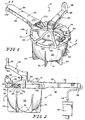
- a bone cement mixing apparatus 10 is provided in accordance with the present invention.
- Mixing apparatus 10 is configured to receive a quantity of bone cement and monomer and mix the cement and monomer under a vacuum. The mixture may then be removed and applied in a prosthesis or deposited in a cement delivery device. As shown in Figs. 1 and 2, mixing apparatus 10 comprises a bowl 12 and a lid 14 coupled to bowl 12.
- bowl 12 includes an inner surface 16 that defines a cavity 18, an outer surface 20, and an upper rim 22 extending between inner and outer surfaces 16, 18.
- shims 23 extend intermittently about rim 22 of bowl 12.
- each shim 23 has a slight depending slope 27 (Fig. 2) formed at a bottom surface 25 so that as lid 14 engages bottom surface 25, the slope forces lid 14 to make a tighter fit against rim 18.
- outer surface 20 is formed to include leg flanges 24 that serve as a stable base.
- lid 14 covers bowl 12, being sealably and removably attachable so that air does not escape between lid 14 and bowl 12.
- Lid 14 is removable so that dry bone cement can be placed into cavity 18 of bowl 12, and the wet bone cement can be removed from cavity 18 after the dry bone cement is mixed with a monomer.
- Lid 14 comprises a cover 26 and a handle 28 extending from cover 26.
- Cover 26 includes an outer surface 30 and an inner surface 32 facing inner surface 16 of bowl 12. As shown in Fig. 2, a ridge 50 extends about an outer perimeter of cover 26. In addition, several intermittent annular flanges 52 extend radially inward from ridge 50. Thus, when lid 14 is placed over rim 18 of bowl 12 and is rotated, each intermittent flange 52 contacts bottom surface 25 of corresponding shim 23. In addition, slots 33 extend through cover 26 in general alignment with a gasket 54, which extends across slots 33 to prevent air and vapors from leaking therethrough. Gasket 54 is positioned between lid 14 and rim 18, assisting in creating a seal between the two components.
- cover is formed to include a vacuum passageway 55 extending therethrough.
- Vacuum passageway 55 includes a vacuum inlet 57 formed through inner surface 32 of cover 26 and a vacuum outlet 56 positioned to lie adjacent to handle 28.
- Cover 26 also includes a luer lock 34 and a crank mount 42 extending from outer surface 30 and defining a shaftway 44.
- Luer lock 34 includes a body 35 that defines a delivery port 36 extending between inner and outer surfaces 32, 30.
- luer lock 34 includes a cap 38 that is sized for extension into delivery port 36 and that removably seals body 35 and a tether 40 extending between cap 38 and body 35.
- Luer lock 34 is configured such that a luer or spout from a monomer dispensing device (not shown) may be extended through delivery port 36 forming a sealing fit with body 35.
- luer lock 34 allows monomer to be dispensed into bowl 12 while preventing monomer vapors from escaping between the luer (not shown) and luer lock 34.
- Cap 38 is used to seal body 35 after the monomer has been dispensed into bowl 12 and during the mixing process. Cap 38 is shown in a disengaged position in Fig. 2. Cap 38 is removed from body 35 in anticipation for the luer attached to the monomer dispensing device (not shown) being inserted for the purpose of transferring monomer from the dispensing device into mixing bowl 2. It will be appreciated that a variety of luer locks and luer lock caps may be used in place of luer lock 34. For example, a self-closing luer lock may be used eliminating even the need for luer cap 38 or a threaded luer lock may be used to screw cap 38 onto body 35. In another embodiment, the monomer dispensing device (not shown) itself may be used as a seal for the luer lock.
- Handle 28 of lid 14 extends from cover 26.
- handle 28 serves a dual function. First, as a grippable body for an operator to hold while mixing the bone cement, and second, to provide a conduit for vacuum outlet 56 (see Figs. 3 and 6) and a vacuum tube 58 (see Fig. 2). It is appreciated, however, that handle 28 may be placed anywhere on mixing apparatus 10.
- handle 28, in another illustrative embodiment may be attached to bowl 12 (not shown).
- vacuum outlet 56 may be disposed through bowl 12.
- Handle 28 includes a top wall 94, side walls 96, and opposite end walls 100, 102 that cooperate to define a cavity 98 therebetween.
- at least one tube grip 104 extends from top wall 94 into cavity 98.
- mixing apparatus 10 includes a crank 60 corotatably coupled to lid 14.
- Crank 60 is used by the operator to drive a blade 62 off-set positioned inside bowl 12 and non-concentrically connected to crank 60 to mix the monomer and bone cement together.
- One end 64 of crank 60 is rotatably extended through shaftway 44, generally at the center of cover 26, while the other end 66 of crank 60 is attached to a knob 68.
- Crank 60 further includes legs 72 that are sized for rotation in shaftway 44 and are coupled to blade 62.
- end 64 of crank 60 is coupled to blade 62.
- Crank 60 is configured to rotate about a longitudinal axis 70 of shaftway 44 which is illustratively the same as the axis of rotation of cover 26.
- Knob 68 is configured to serve as a grip which the operator may grasp to rotate crank 60 thereby causing blade 62 to rotate. It is appreciated that knob 68 may also be configured to rotatably or fixedly attach to crank 60. In addition, a small o-ring 29 is fitted between legs 72 and crank mount 42 in shaftway 44 to prevent the escape of air or vapor between lid 14 and crank 60.
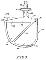
- blade 62 includes a generally U-shaped body 74 that has a non-symmetrical extended curved side 120, a generally linear side 122 opposite curved side 120, and a rounded bottom 124 connecting to sides 120, 122, Sides 120, 122 cooperate to define opposite ends 78, 80 of U-shaped body 74.
- blade 62 includes a plane top or shoulder blade 76 extending between and connecting opposite ends 78, 80 of body 74 and a vane 82 extending from one of the ends 78 of body 74 to rounded bottom 124 to define a first aperture 84 and a second aperture 86 and to shear and mix the cement nearer the center of bowl 12.
- blade 62 includes a shaft 88 that extends from shoulder blade 76 and a collar 90 coupled to shaft 88.
- Shaft 88 extends upward from shoulder blade 76 into shaftway 44 and frictionally coupled to depending legs 72. It is understood, however, that the present invention is not limited to only a frictional fit between shaft 88 and crank 60. Any variety of means may connect blade 62 to crank 60, and are contemplated by the present invention. For example, a snap-fit or connectable threads may accomplish the same function. Collar 90 is configured to limit the length with which shaft 88 may extend through shaftway 44. Thus collar engages inner surface 32 of cover 26 to ensure proper placement of blade 62 in cavity 18 of bowl 12. Shaft 88 is also laterally offset from the longitudinal center 106 of blade 62. This offset placement creates additional shearing action per revolution of crank 60. The additional shearing action reduces the amount of mixing required to produce the wet cement.
- crank 60 rotatably extends through shaftway 44 attaching itself to blade 62
- blade 62 rotates as crank 60 is rotated by the operator thereby mixing the monomer with the cement inside bowl 12.
- Fig. 4 for optimum mixing, at least a portion of blade 62 passes in close proximity to inner wall 22 of bowl 12 as well as being offset relative to shaft 20.
- at least a portion of blade 62 contours about one quarter the circumference of bowl 12 and along a plane generally parallel to longitudinal axis 70 of shaftway 44.
- vacuum tube 58 is coupled to vacuum outlet 56.
- vacuum tube 58 extends through end wall 102 and into cavity 98 of handle 28 so as not to interfere with the operator as apparatus 10 is being used.
- Vacuum tube 58 is also connectable to a vacuum pump 92 (Fig. 2) designed to draw air from mixing apparatus 10 through vacuum outlet 56.
- Vacuum tube 58 is illustratively secured into place by tube grips 104, which aid in ensuring that vacuum tube 58 remains coupled to vacuum outlet 56.
- lid 14 is rotated in an opposite direction 108 (Fig. 1) thereby releasing flanges 52 from shims 23 allowing removal of lid 14 from bowl 12.
- a spatula 110 may be used to remove the cement mixture from bowl 12.
- Spatula 110 includes a handle 112 and a blade 114 coupled to handle 112. Blade 114 is formed to have a curved outer edge 116 that is formed in the partial shape of the contour of inner wall 22.
- Handle 112 may be gripped by the operator to scoop out the wet cement from cavity 18, using blade 112, for deposit in a cement dispensing device (not shown) or directly onto a prosthetic setting (not shown).
- blade 162 is provided in accordance with the present invention to be used in place of blade 62.
- Blade 162 is formed similarly to blade 62 and like reference numerals will be used to denote like components.
- Blade 162 is formed to include an angled shoulder blade 176.
- shoulder blade 176 includes a first portion 178 and a second tapered portion 180 that forms an angle generally obtuse from shaft 88.
- the angle of shoulder blade identified by reference number 182 is about -15° relative to horizontal line 188. It is appreciated, however, that the angle of tapered portion 180 may be anywhere above or below horizontal line 188.
- a quantity of bone cement powder is placed in cavity 18 of bowl 12.
- lid 14 is placed over rim 22 and rotated until each flange 52 contacts bottom surface 25 of corresponding shim 23 to press seal 54 against rim 18 and form a seal therebetween.
- monomer may added to the bone cement powder.
- cap 38 is removed from body 35 of luer lock 34. Thereafter, vacuum pump 14 is activated generating a vacuum within bowl 12 to expel air from cavity 18 out through vacuum outlet 56 and tube 58. It is preferable to generate a vacuum in cavity 18 of about 0.67 to 0.73 bar, just below the boiling point of the monomer creating the maximum vacuum pressure in bowl 12 without the monomer boiling.
- the luer or similar structure from the monomer dispensing device (not shown) is inserted into delivery port 36 of body 35 to form a generally sealed connection at which time the monomer may be deposited into bowl 12.
- the vacuum pump 92 will expel from apparatus 10 any monomer vapors generated by the deposition of the monomer in bowl 12.
- the luer from the monomer delivery device (not shown) is removed from luer lock 34 and luer cap 38 is immediately fitted into delivery port 36, as shown by arrow 111 in Fig. 2.
- crank 60 causes body 74 and vane 82 of blade 62 to begin rotating within bowl 12 shearing and mixing the bone cement with the monomer, as previously discussed.
- An illustrative stirring time for efficient stirring of the mixture is about 45 to 60 seconds. It is preferable that the vacuum remains evacuating vapors from the mixture for about an additional 15 to 20 seconds after mixing has been completed to remove any excess air or monomer vapor from the bone cement mixture.
- Lid 14 is then rotated on bowl in direction 108 as previously discussed. The operator may then use spatula 110 to scrape the wet bone cement out from bowl 12. The wet bone cement can then be placed into a bone cement dispensing device (not shown) to then be applied to a prosthesis.
Landscapes
- Chemical & Material Sciences (AREA)
- Chemical Kinetics & Catalysis (AREA)
- Dispersion Chemistry (AREA)
- Engineering & Computer Science (AREA)
- Mechanical Engineering (AREA)
- Structural Engineering (AREA)
- Mixers Of The Rotary Stirring Type (AREA)
- Materials For Medical Uses (AREA)
- Accessories For Mixers (AREA)
- Prostheses (AREA)
- Preparation Of Clay, And Manufacture Of Mixtures Containing Clay Or Cement (AREA)
- Surgical Instruments (AREA)
- Processing Of Solid Wastes (AREA)
- Soil Conditioners And Soil-Stabilizing Materials (AREA)
Abstract
Description
Claims (20)
- A bone cement mixing apparatus comprising:a bowl;a lid removably attached to the bowl having a sealable monomer delivery port disposed therethrough;a crank having a portion extending through the lid, said crank being rotatably attached to the lid; anda blade positioned in the bowl and attached to that portion of the crank extended through the lid such that the blade rotates with the crank.
- The apparatus of claim 1, wherein the lid also comprises a handle.
- The apparatus of claim 1, wherein the lid also comprises a vacuum outlet tube for attachment to a vacuum.
- The apparatus of claim 2, wherein the handle comprises a vacuum outlet tube and tube grips for attachment to a vacuum source and vacuum tube.
- The apparatus of claim 1, wherein the bowl also comprises a vacuum outlet tube for attachment to a vacuum.
- The apparatus of claim 1, wherein the bowl further comprises a plurality of intermittent shims placed about the circumference of the bowl and the lid shroudes the bowl and has a plurality of annular intermittent flanges formed about the edge of the lid, whereby each flange cooperates with an intermittent shim on the bowl removably and sealably attaching the lid to the bowl.
- The apparatus of claim 1, further comprising a portion of the blade contouring about one quarter the circumference of the bowl along a plane parallel to the longitudinal axis of the blade.
- The apparatus of claim 7, wherein the blade further comprises an angled shoulder blade.
- The apparatus of claim 6, wherein the blade further comprises a vane fitted within the blade.
- The apparatus of claim 1, wherein the sealable port also comprises a luer port cap that selectively seals the port.
- The apparatus of claim 1, wherein the blade is a U-shaped blade having a non-symmetrical extended curved side, a linear side opposite the curved side, a rounded bottom connecting to the linear side and the curved side, a plane top laterally extending also connecting to the linear side and the curved side, a vane extending from the plane top to the rounded bottom, and a shaft extending from the plane top.
- The apparatus of claim 11, wherein the plane top comprises an angled shoulder blade.
- The apparatus of claim 1, wherein the blade is positioned in the bowl and attached to that portion of the crank extended through the lid such that the blade rotates non-concentrically with the crank.
- The apparatus of claim 11, wherein the shaft is extending from a non-symmetrical position on the plane top.
- A bone cement mixing apparatus comprising:a bowl,a lid removably coupled to the bowl, the lid including a cover formed to include a delivery port therethrough and a cap formed for extension into the delivery port to selectively seal the port,a crank extending through and rotatably coupled to the lid, anda blade positioned in the bowl and coupled to the crank so that the blade rotates with the crank.
- The apparatus of claim 15, wherein the lid includes a handle extending outwardly from the cover.
- The apparatus of claim 16, wherein the lid is formed to include a vacuum passageway extending between the cover and the handle.
- The apparatus of claim 15, wherein the blade is formed to include a body portion and a shoulder blade extending between opposite ends of the body portion.
- The apparatus of claim 18, wherein the shoulder blade includes a tapered portion.
- The apparatus of claim 18, wherein the blade is formed to include vane extending across the body portion.
Applications Claiming Priority (2)
| Application Number | Priority Date | Filing Date | Title |
|---|---|---|---|
| US09/354,634 US6254268B1 (en) | 1999-07-16 | 1999-07-16 | Bone cement mixing apparatus |
| US354634 | 2003-01-29 |
Publications (3)
| Publication Number | Publication Date |
|---|---|
| EP1068893A2 true EP1068893A2 (en) | 2001-01-17 |
| EP1068893A3 EP1068893A3 (en) | 2001-12-05 |
| EP1068893B1 EP1068893B1 (en) | 2004-04-14 |
Family
ID=23394255
Family Applications (1)
| Application Number | Title | Priority Date | Filing Date |
|---|---|---|---|
| EP00305995A Expired - Lifetime EP1068893B1 (en) | 1999-07-16 | 2000-07-14 | Bone cement mixing apparatus |
Country Status (9)
| Country | Link |
|---|---|
| US (1) | US6254268B1 (en) |
| EP (1) | EP1068893B1 (en) |
| JP (1) | JP4812925B2 (en) |
| KR (1) | KR20010039720A (en) |
| AT (1) | ATE264136T1 (en) |
| AU (1) | AU775404B2 (en) |
| DE (1) | DE60009802T2 (en) |
| DK (1) | DK1068893T3 (en) |
| NZ (1) | NZ505705A (en) |
Cited By (1)
| Publication number | Priority date | Publication date | Assignee | Title |
|---|---|---|---|---|
| EP1348479A1 (en) * | 2002-03-29 | 2003-10-01 | Depuy Orthopaedics, Inc. | Bone cement mixing apparatus |
Families Citing this family (29)
| Publication number | Priority date | Publication date | Assignee | Title |
|---|---|---|---|---|
| US7175336B2 (en) * | 2001-01-26 | 2007-02-13 | Depuy Acromed, Inc. | Graft delivery system |
| US7008433B2 (en) | 2001-02-15 | 2006-03-07 | Depuy Acromed, Inc. | Vertebroplasty injection device |
| WO2003078041A1 (en) * | 2002-03-14 | 2003-09-25 | Stryker Instruments | Mixing assembly for mixing bone cement |
| SE519349C2 (en) * | 2002-04-18 | 2003-02-18 | Cemvac System Ab | Bone cement preparation device, comprises mixing bowl and blades mounted in lid |
| GB2398741B (en) * | 2003-02-05 | 2005-04-13 | Summit Medical Ltd | Orthopaedic cement mixing device |
| ES2545328T3 (en) | 2003-03-14 | 2015-09-10 | Depuy Spine, Inc. | Bone cement hydraulic injection device in percutaneous vertebroplasty |
| US8066713B2 (en) | 2003-03-31 | 2011-11-29 | Depuy Spine, Inc. | Remotely-activated vertebroplasty injection device |
| WO2006011152A2 (en) | 2004-06-17 | 2006-02-02 | Disc-O-Tech Medical Technologies, Ltd. | Methods for treating bone and other tissue |
| US8415407B2 (en) | 2004-03-21 | 2013-04-09 | Depuy Spine, Inc. | Methods, materials, and apparatus for treating bone and other tissue |
| WO2005030034A2 (en) | 2003-09-26 | 2005-04-07 | Depuy Spine, Inc. | Device for delivering viscous material |
| US7524103B2 (en) * | 2003-11-18 | 2009-04-28 | Boston Scientific Scimed, Inc. | Apparatus for mixing and dispensing a multi-component bone cement |
| US20080319445A9 (en) * | 2004-08-17 | 2008-12-25 | Scimed Life Systems, Inc. | Apparatus and methods for delivering compounds into vertebrae for vertebroplasty |
| US8038682B2 (en) * | 2004-08-17 | 2011-10-18 | Boston Scientific Scimed, Inc. | Apparatus and methods for delivering compounds into vertebrae for vertebroplasty |
| US8029183B2 (en) * | 2005-02-23 | 2011-10-04 | Biomet Manufacturing Corp. | Apparatus for mixing bone cement |
| US9381024B2 (en) | 2005-07-31 | 2016-07-05 | DePuy Synthes Products, Inc. | Marked tools |
| US9918767B2 (en) * | 2005-08-01 | 2018-03-20 | DePuy Synthes Products, Inc. | Temperature control system |
| FR2892097B1 (en) * | 2005-10-14 | 2008-01-04 | Thierry Claude Leon Garcia | MULTI-PURPOSE COVER, IN PARTICULAR FOR LIQUIDS, IN PARTICULAR FOR PAINT POT. |
| US8360629B2 (en) | 2005-11-22 | 2013-01-29 | Depuy Spine, Inc. | Mixing apparatus having central and planetary mixing elements |
| WO2008032322A2 (en) | 2006-09-14 | 2008-03-20 | Depuy Spine, Inc. | Bone cement and methods of use thereof |
| ES2587573T3 (en) | 2006-10-19 | 2016-10-25 | Depuy Spine, Inc. | Fluid release system and related method |
| WO2009153196A1 (en) | 2008-06-19 | 2009-12-23 | Basf Se | Method for continuously producing water-absorbing polymer particles |
| US9308506B2 (en) * | 2009-01-21 | 2016-04-12 | Medmix Systems Ag | Mixing apparatus having display for pressure change |
| US8434403B1 (en) | 2010-12-15 | 2013-05-07 | Magellan Group Ltd. | Popcorn popper |
| US20130269826A1 (en) * | 2012-04-13 | 2013-10-17 | Kyphon Sarl | Bone Cement Component Injection System With Reduced Fume Exposure And Method |
| JP2014012261A (en) * | 2012-07-05 | 2014-01-23 | Inoue Mfg Inc | Planetary mixer |
| USD753429S1 (en) * | 2014-09-05 | 2016-04-12 | Zippy Pop Inc. | Snack machine |
| KR101645576B1 (en) | 2014-10-01 | 2016-08-05 | 백은정 | Bone Cement Mixing Device |
| CN112168324B (en) * | 2019-07-04 | 2022-09-06 | 北京中科盛康科技有限公司 | Bone cement stirrer |
| AU2023382161A1 (en) * | 2022-11-14 | 2024-11-07 | Medisca Pharmaceutique Inc. | Methods and systems for making oil-loaded powders and use thereof |
Family Cites Families (50)
| Publication number | Priority date | Publication date | Assignee | Title |
|---|---|---|---|---|
| US856295A (en) * | 1905-06-26 | 1907-06-11 | Rotary Machine Company | Cutting and mixing mill. |
| US1101199A (en) * | 1912-12-28 | 1914-06-23 | Walter F Legg | Batter cup or bucket. |
| GB178572A (en) | 1921-01-21 | 1922-04-21 | James Harold Williams | Improvements in vessels for containing and spraying paints, varnishes, and the like |
| US1459148A (en) * | 1921-12-27 | 1923-06-19 | Anthony I Flynt | Mixing and beating device |
| US1698402A (en) * | 1927-05-25 | 1929-01-08 | Glenn A Harris | Rotatable agitator and scraper |
| US2150888A (en) * | 1938-02-21 | 1939-03-14 | Therides V Barnard | Corn popper |
| GB517340A (en) | 1938-07-25 | 1940-01-26 | B B Chem Co Ltd | Improvements in or relating to stirring or agitating of the contents of cans or the like |
| US2269736A (en) | 1940-09-06 | 1942-01-13 | Leon Finch Ltd | Dispensing device |
| US2570126A (en) * | 1948-04-05 | 1951-10-02 | Us Mfg Corp | Popcorn popping device |
| US2561203A (en) * | 1949-06-04 | 1951-07-17 | Joffe Morris | Corn popping device |
| US2696022A (en) * | 1951-04-23 | 1954-12-07 | Steinbock | Investment mixer |
| US2898094A (en) * | 1956-01-16 | 1959-08-04 | Union Machine Company | Paint mixer |
| US3053457A (en) | 1960-08-18 | 1962-09-11 | Pyles Ind Inc | Demand mixing and dispensing gun for multicomponent materials |
| JPS4218874Y1 (en) * | 1964-05-20 | 1967-10-31 | ||
| US3640510A (en) | 1969-09-26 | 1972-02-08 | Degussa | Vacuum stirring device for dental materials |
| US3704007A (en) * | 1970-07-29 | 1972-11-28 | Paul T Kroeger | Paint can agitator and pouring top |
| CA1021767A (en) | 1974-01-11 | 1977-11-29 | Samuel J. Popeil | Orbital whipper having rotatable beaters |
| US4185072A (en) | 1977-02-17 | 1980-01-22 | Diemolding Corporation | Orthopedic cement mixer |
| US4149455A (en) * | 1978-03-17 | 1979-04-17 | Ross Michael M | Electric pop corn popper |
| US4460279A (en) * | 1982-08-25 | 1984-07-17 | Krasney Robert L | Liquid pitcher with mixer |
| CA1218243A (en) * | 1983-07-07 | 1987-02-24 | Nippon Light Metal Co., Ltd. | Device for making frozen confections |
| DE3425566A1 (en) | 1984-07-11 | 1986-01-16 | Draenert Klaus | DEVICE AND METHOD FOR MIXING AND APPLYING BONE CEMENT |
| SE450545B (en) | 1984-10-19 | 1987-07-06 | Mit Ab | PROCEDURE AND DEVICE FOR MANUFACTURING BENCEMENT FOR FIXING PROSTHESIS |
| SE447785B (en) | 1985-12-23 | 1986-12-15 | Mit Ab | DEVICE FOR APPLIANCES TO ALLOW BENCEMENT MIXING UNDER VACUUM |
| US4961647A (en) | 1986-04-04 | 1990-10-09 | Dhd Medical Products | Orthopedic cement mixer |
| FR2597321A1 (en) | 1986-04-22 | 1987-10-23 | Vivalp | Electric household appliance for preparing sauces |
| US4787751A (en) | 1986-06-20 | 1988-11-29 | Marinus Bakels | Bone cement mixing device |
| JPH02503761A (en) | 1987-04-23 | 1990-11-08 | ダイモウルディング コーポレーション | Orthopedic cement mixer |
| CH669080GA3 (en) | 1987-05-14 | 1989-02-28 | ||
| US5374121A (en) | 1987-05-21 | 1994-12-20 | Draenert; Klaus | Mixing apparatus with mixing rod supporting lid |
| CA1280109C (en) * | 1987-07-08 | 1991-02-12 | Laszlo Murzsa | Paint mixing container |
| SE462315B (en) | 1989-05-03 | 1990-06-11 | Surgitec Ab | DEVICE FOR MANUFACTURING BENCEMENT |
| DE3919534A1 (en) | 1989-06-15 | 1990-12-20 | Merck Patent Gmbh | METHOD AND DEVICE FOR PREPARING BONE CEMENT |
| US5435645A (en) * | 1989-12-29 | 1995-07-25 | Tecres Spa | Process and apparatus for the mixing and direct emplacement of a two-component bone cement |
| US5199788A (en) * | 1990-02-12 | 1993-04-06 | Dorothy Stallings | Apparatus for sealing a liquid container |
| US5265956A (en) | 1991-09-30 | 1993-11-30 | Stryker Corporation | Bone cement mixing and loading apparatus |
| GB9126011D0 (en) | 1991-12-06 | 1992-02-05 | Summit Medical Ltd | Bone cement mixing device |
| SE510490C2 (en) | 1992-02-07 | 1999-05-31 | Scandimed International Ab | Process for producing bone cement and apparatus for carrying out the process |
| WO1995001832A1 (en) | 1993-07-06 | 1995-01-19 | Earle Michael L | Automated bone cement mixing apparatus |
| US5531519A (en) | 1993-07-06 | 1996-07-02 | Earle; Michael L. | Automated bone cement mixing apparatus |
| US5472445A (en) | 1993-09-20 | 1995-12-05 | Zimmer, Inc. | Device for minimizing porosity in bone cement utilizing centrifugation and vacuum |
| US5368386A (en) | 1993-11-16 | 1994-11-29 | Murray; William M. | Manual bone cement mixing device |
| US5558136A (en) | 1994-01-31 | 1996-09-24 | Stryker Corporation | Bone cement cartridge with secondary piston |
| DE4425218A1 (en) | 1994-07-16 | 1996-01-18 | Merck Patent Gmbh | Device for mixing and discharging bone cement |
| US5549381A (en) | 1995-05-19 | 1996-08-27 | Hays; Greta J. | Method and apparatus for mixing polymeric bone cement components |
| US5797678A (en) * | 1995-09-25 | 1998-08-25 | Murray; William M. | Bone cement mixing device and method |
| US5586821A (en) | 1995-10-10 | 1996-12-24 | Zimmer, Inc. | Bone cement preparation kit |
| US5797679A (en) * | 1996-02-09 | 1998-08-25 | Stryker Corporation | Surgical cement mixer apparatus |
| US5876116A (en) * | 1996-11-15 | 1999-03-02 | Barker; Donald | Integrated bone cement mixing and dispensing system |
| US6042262A (en) | 1997-07-29 | 2000-03-28 | Stryker Technologies Corportion | Apparatus for storing, mixing, and dispensing two-component bone cement |
-
1999
- 1999-07-16 US US09/354,634 patent/US6254268B1/en not_active Expired - Lifetime
-
2000
- 2000-07-12 NZ NZ505705A patent/NZ505705A/en unknown
- 2000-07-13 AU AU47212/00A patent/AU775404B2/en not_active Expired
- 2000-07-14 EP EP00305995A patent/EP1068893B1/en not_active Expired - Lifetime
- 2000-07-14 AT AT00305995T patent/ATE264136T1/en not_active IP Right Cessation
- 2000-07-14 DK DK00305995T patent/DK1068893T3/en active
- 2000-07-14 DE DE60009802T patent/DE60009802T2/en not_active Expired - Lifetime
- 2000-07-14 KR KR1020000040476A patent/KR20010039720A/en not_active Withdrawn
- 2000-07-17 JP JP2000216329A patent/JP4812925B2/en not_active Expired - Lifetime
Cited By (2)
| Publication number | Priority date | Publication date | Assignee | Title |
|---|---|---|---|---|
| EP1348479A1 (en) * | 2002-03-29 | 2003-10-01 | Depuy Orthopaedics, Inc. | Bone cement mixing apparatus |
| US6921192B2 (en) | 2002-03-29 | 2005-07-26 | Depuy Orthopaedics, Inc. | Bone cement mixing apparatus |
Also Published As
| Publication number | Publication date |
|---|---|
| JP2001079826A (en) | 2001-03-27 |
| DE60009802D1 (en) | 2004-05-19 |
| ATE264136T1 (en) | 2004-04-15 |
| EP1068893B1 (en) | 2004-04-14 |
| KR20010039720A (en) | 2001-05-15 |
| US6254268B1 (en) | 2001-07-03 |
| AU4721200A (en) | 2001-01-18 |
| JP4812925B2 (en) | 2011-11-09 |
| NZ505705A (en) | 2000-10-27 |
| AU775404B2 (en) | 2004-07-29 |
| DK1068893T3 (en) | 2004-07-19 |
| EP1068893A3 (en) | 2001-12-05 |
| DE60009802T2 (en) | 2005-03-17 |
Similar Documents
| Publication | Publication Date | Title |
|---|---|---|
| US6254268B1 (en) | Bone cement mixing apparatus | |
| US6921192B2 (en) | Bone cement mixing apparatus | |
| JP3247698B2 (en) | Bone cement mixing equipment | |
| EP1210975B1 (en) | Bone cement mixing apparatus with gearing arrangement for driving a mixing blade | |
| US6435705B1 (en) | Apparatus and method for delivering and mixing a liquid bone cement component with a powder bone cement component | |
| JP3238706B2 (en) | Bone cement mixing equipment | |
| EP0178658A2 (en) | Method for producing bone cement for fixing protheses and device for carrying out said method | |
| AU778168B2 (en) | Bone cement mixing apparatus having improved mixing blade configuration | |
| EP1466572A2 (en) | Device for packaging, mixing and applying bone cement | |
| AU2018217282B2 (en) | An apparatus for mixing and delivering bone cement | |
| KR101645576B1 (en) | Bone Cement Mixing Device | |
| EP4491267A1 (en) | Mixing and dispensing system for a two-component material and method of mixing and dispensing two-component material | |
| GB2606509A (en) | Mixing container with dust extraction |
Legal Events
| Date | Code | Title | Description |
|---|---|---|---|
| PUAI | Public reference made under article 153(3) epc to a published international application that has entered the european phase |
Free format text: ORIGINAL CODE: 0009012 |
|
| AK | Designated contracting states |
Kind code of ref document: A2 Designated state(s): AT BE CH CY DE DK ES FI FR GB GR IE IT LI LU MC NL PT SE |
|
| AX | Request for extension of the european patent |
Free format text: AL;LT;LV;MK;RO;SI |
|
| PUAL | Search report despatched |
Free format text: ORIGINAL CODE: 0009013 |
|
| AK | Designated contracting states |
Kind code of ref document: A3 Designated state(s): AT BE CH CY DE DK ES FI FR GB GR IE IT LI LU MC NL PT SE |
|
| AX | Request for extension of the european patent |
Free format text: AL;LT;LV;MK;RO;SI |
|
| 17P | Request for examination filed |
Effective date: 20020521 |
|
| AKX | Designation fees paid |
Free format text: AT BE CH CY DE DK ES FI FR GB GR IE IT LI LU MC NL PT SE |
|
| 17Q | First examination report despatched |
Effective date: 20020927 |
|
| RAP1 | Party data changed (applicant data changed or rights of an application transferred) |
Owner name: DEPUY ORTHOPAEDICS, INC. |
|
| GRAP | Despatch of communication of intention to grant a patent |
Free format text: ORIGINAL CODE: EPIDOSNIGR1 |
|
| GRAS | Grant fee paid |
Free format text: ORIGINAL CODE: EPIDOSNIGR3 |
|
| GRAA | (expected) grant |
Free format text: ORIGINAL CODE: 0009210 |
|
| AK | Designated contracting states |
Kind code of ref document: B1 Designated state(s): AT BE CH CY DE DK ES FI FR GB GR IE IT LI LU MC NL PT SE |
|
| PG25 | Lapsed in a contracting state [announced via postgrant information from national office to epo] |
Ref country code: CY Free format text: LAPSE BECAUSE OF FAILURE TO SUBMIT A TRANSLATION OF THE DESCRIPTION OR TO PAY THE FEE WITHIN THE PRESCRIBED TIME-LIMIT Effective date: 20040414 Ref country code: FI Free format text: LAPSE BECAUSE OF FAILURE TO SUBMIT A TRANSLATION OF THE DESCRIPTION OR TO PAY THE FEE WITHIN THE PRESCRIBED TIME-LIMIT Effective date: 20040414 Ref country code: NL Free format text: LAPSE BECAUSE OF FAILURE TO SUBMIT A TRANSLATION OF THE DESCRIPTION OR TO PAY THE FEE WITHIN THE PRESCRIBED TIME-LIMIT Effective date: 20040414 Ref country code: AT Free format text: LAPSE BECAUSE OF FAILURE TO SUBMIT A TRANSLATION OF THE DESCRIPTION OR TO PAY THE FEE WITHIN THE PRESCRIBED TIME-LIMIT Effective date: 20040414 Ref country code: BE Free format text: LAPSE BECAUSE OF FAILURE TO SUBMIT A TRANSLATION OF THE DESCRIPTION OR TO PAY THE FEE WITHIN THE PRESCRIBED TIME-LIMIT Effective date: 20040414 |
|
| REG | Reference to a national code |
Ref country code: GB Ref legal event code: FG4D |
|
| REG | Reference to a national code |
Ref country code: CH Ref legal event code: EP |
|
| REF | Corresponds to: |
Ref document number: 60009802 Country of ref document: DE Date of ref document: 20040519 Kind code of ref document: P |
|
| REG | Reference to a national code |
Ref country code: IE Ref legal event code: FG4D |
|
| REG | Reference to a national code |
Ref country code: CH Ref legal event code: NV Representative=s name: E. BLUM & CO. PATENTANWAELTE |
|
| REG | Reference to a national code |
Ref country code: SE Ref legal event code: TRGR |
|
| PG25 | Lapsed in a contracting state [announced via postgrant information from national office to epo] |
Ref country code: GR Free format text: LAPSE BECAUSE OF FAILURE TO SUBMIT A TRANSLATION OF THE DESCRIPTION OR TO PAY THE FEE WITHIN THE PRESCRIBED TIME-LIMIT Effective date: 20040714 Ref country code: LU Free format text: LAPSE BECAUSE OF NON-PAYMENT OF DUE FEES Effective date: 20040714 |
|
| REG | Reference to a national code |
Ref country code: DK Ref legal event code: T3 |
|
| PG25 | Lapsed in a contracting state [announced via postgrant information from national office to epo] |
Ref country code: ES Free format text: LAPSE BECAUSE OF FAILURE TO SUBMIT A TRANSLATION OF THE DESCRIPTION OR TO PAY THE FEE WITHIN THE PRESCRIBED TIME-LIMIT Effective date: 20040725 |
|
| PG25 | Lapsed in a contracting state [announced via postgrant information from national office to epo] |
Ref country code: MC Free format text: LAPSE BECAUSE OF NON-PAYMENT OF DUE FEES Effective date: 20040731 |
|
| NLV1 | Nl: lapsed or annulled due to failure to fulfill the requirements of art. 29p and 29m of the patents act | ||
| ET | Fr: translation filed | ||
| PLBE | No opposition filed within time limit |
Free format text: ORIGINAL CODE: 0009261 |
|
| STAA | Information on the status of an ep patent application or granted ep patent |
Free format text: STATUS: NO OPPOSITION FILED WITHIN TIME LIMIT |
|
| 26N | No opposition filed |
Effective date: 20050117 |
|
| REG | Reference to a national code |
Ref country code: CH Ref legal event code: PFA Owner name: DEPUY ORTHOPAEDICS, INC. Free format text: DEPUY ORTHOPAEDICS, INC.#700 ORTHOPAEDIC DRIVE#WARSAW, IN 46581 (US) -TRANSFER TO- DEPUY ORTHOPAEDICS, INC.#700 ORTHOPAEDIC DRIVE#WARSAW, IN 46581 (US) |
|
| PG25 | Lapsed in a contracting state [announced via postgrant information from national office to epo] |
Ref country code: PT Free format text: LAPSE BECAUSE OF NON-PAYMENT OF DUE FEES Effective date: 20040914 |
|
| PGFP | Annual fee paid to national office [announced via postgrant information from national office to epo] |
Ref country code: DK Payment date: 20150713 Year of fee payment: 16 |
|
| PGFP | Annual fee paid to national office [announced via postgrant information from national office to epo] |
Ref country code: SE Payment date: 20150713 Year of fee payment: 16 |
|
| REG | Reference to a national code |
Ref country code: FR Ref legal event code: PLFP Year of fee payment: 17 |
|
| REG | Reference to a national code |
Ref country code: DK Ref legal event code: EBP Effective date: 20170131 |
|
| REG | Reference to a national code |
Ref country code: SE Ref legal event code: EUG |
|
| PG25 | Lapsed in a contracting state [announced via postgrant information from national office to epo] |
Ref country code: SE Free format text: LAPSE BECAUSE OF NON-PAYMENT OF DUE FEES Effective date: 20160715 |
|
| REG | Reference to a national code |
Ref country code: FR Ref legal event code: PLFP Year of fee payment: 18 |
|
| PG25 | Lapsed in a contracting state [announced via postgrant information from national office to epo] |
Ref country code: DK Free format text: LAPSE BECAUSE OF NON-PAYMENT OF DUE FEES Effective date: 20160731 |
|
| REG | Reference to a national code |
Ref country code: FR Ref legal event code: PLFP Year of fee payment: 19 |
|
| PGFP | Annual fee paid to national office [announced via postgrant information from national office to epo] |
Ref country code: FR Payment date: 20190619 Year of fee payment: 20 |
|
| PGFP | Annual fee paid to national office [announced via postgrant information from national office to epo] |
Ref country code: IE Payment date: 20190710 Year of fee payment: 20 Ref country code: IT Payment date: 20190719 Year of fee payment: 20 Ref country code: DE Payment date: 20190702 Year of fee payment: 20 |
|
| PGFP | Annual fee paid to national office [announced via postgrant information from national office to epo] |
Ref country code: GB Payment date: 20190710 Year of fee payment: 20 |
|
| PGFP | Annual fee paid to national office [announced via postgrant information from national office to epo] |
Ref country code: CH Payment date: 20190718 Year of fee payment: 20 |
|
| REG | Reference to a national code |
Ref country code: DE Ref legal event code: R071 Ref document number: 60009802 Country of ref document: DE |
|
| REG | Reference to a national code |
Ref country code: CH Ref legal event code: PL |
|
| REG | Reference to a national code |
Ref country code: GB Ref legal event code: PE20 Expiry date: 20200713 |
|
| REG | Reference to a national code |
Ref country code: IE Ref legal event code: MK9A |
|
| PG25 | Lapsed in a contracting state [announced via postgrant information from national office to epo] |
Ref country code: GB Free format text: LAPSE BECAUSE OF EXPIRATION OF PROTECTION Effective date: 20200713 Ref country code: IE Free format text: LAPSE BECAUSE OF EXPIRATION OF PROTECTION Effective date: 20200714 |