EP1068513B1 - Improvements in and relating to biomedical assays - Google Patents
Improvements in and relating to biomedical assays Download PDFInfo
- Publication number
- EP1068513B1 EP1068513B1 EP99910524A EP99910524A EP1068513B1 EP 1068513 B1 EP1068513 B1 EP 1068513B1 EP 99910524 A EP99910524 A EP 99910524A EP 99910524 A EP99910524 A EP 99910524A EP 1068513 B1 EP1068513 B1 EP 1068513B1
- Authority
- EP
- European Patent Office
- Prior art keywords
- sample
- measurement
- samples
- radiation
- light
- Prior art date
- Legal status (The legal status is an assumption and is not a legal conclusion. Google has not performed a legal analysis and makes no representation as to the accuracy of the status listed.)
- Expired - Lifetime
Links
- 238000003556 assay Methods 0.000 title claims description 40
- 230000006872 improvement Effects 0.000 title description 2
- 238000005259 measurement Methods 0.000 claims description 31
- 230000005284 excitation Effects 0.000 claims description 29
- 238000000034 method Methods 0.000 claims description 29
- 230000005855 radiation Effects 0.000 claims description 23
- 238000001514 detection method Methods 0.000 claims description 16
- 230000003287 optical effect Effects 0.000 claims description 7
- 238000005286 illumination Methods 0.000 claims description 4
- 239000000203 mixture Substances 0.000 claims description 2
- 238000012935 Averaging Methods 0.000 claims 1
- 239000000523 sample Substances 0.000 description 68
- 239000011159 matrix material Substances 0.000 description 16
- 239000000872 buffer Substances 0.000 description 13
- 238000012937 correction Methods 0.000 description 11
- 238000006073 displacement reaction Methods 0.000 description 8
- 239000000463 material Substances 0.000 description 7
- 230000008859 change Effects 0.000 description 6
- 230000000694 effects Effects 0.000 description 6
- 239000007788 liquid Substances 0.000 description 5
- 239000012528 membrane Substances 0.000 description 5
- GNBHRKFJIUUOQI-UHFFFAOYSA-N fluorescein Chemical compound O1C(=O)C2=CC=CC=C2C21C1=CC=C(O)C=C1OC1=CC(O)=CC=C21 GNBHRKFJIUUOQI-UHFFFAOYSA-N 0.000 description 4
- 230000005499 meniscus Effects 0.000 description 4
- 230000001960 triggered effect Effects 0.000 description 4
- 239000012496 blank sample Substances 0.000 description 3
- 239000007853 buffer solution Substances 0.000 description 3
- 239000000835 fiber Substances 0.000 description 3
- 230000035945 sensitivity Effects 0.000 description 3
- 230000005540 biological transmission Effects 0.000 description 2
- 239000011521 glass Substances 0.000 description 2
- 238000003018 immunoassay Methods 0.000 description 2
- 102000004169 proteins and genes Human genes 0.000 description 2
- 108090000623 proteins and genes Proteins 0.000 description 2
- 238000002310 reflectometry Methods 0.000 description 2
- 239000000243 solution Substances 0.000 description 2
- 239000000758 substrate Substances 0.000 description 2
- 238000009736 wetting Methods 0.000 description 2
- XUIMIQQOPSSXEZ-UHFFFAOYSA-N Silicon Chemical compound [Si] XUIMIQQOPSSXEZ-UHFFFAOYSA-N 0.000 description 1
- 239000000654 additive Substances 0.000 description 1
- 230000000996 additive effect Effects 0.000 description 1
- 239000000853 adhesive Substances 0.000 description 1
- 230000001070 adhesive effect Effects 0.000 description 1
- 238000013459 approach Methods 0.000 description 1
- 238000000149 argon plasma sintering Methods 0.000 description 1
- 239000012472 biological sample Substances 0.000 description 1
- 238000005415 bioluminescence Methods 0.000 description 1
- 230000029918 bioluminescence Effects 0.000 description 1
- 230000000903 blocking effect Effects 0.000 description 1
- 238000011088 calibration curve Methods 0.000 description 1
- 238000000423 cell based assay Methods 0.000 description 1
- 230000001413 cellular effect Effects 0.000 description 1
- 239000003153 chemical reaction reagent Substances 0.000 description 1
- 238000004140 cleaning Methods 0.000 description 1
- 230000007547 defect Effects 0.000 description 1
- 230000023077 detection of light stimulus Effects 0.000 description 1
- 239000000975 dye Substances 0.000 description 1
- 238000003384 imaging method Methods 0.000 description 1
- 238000011065 in-situ storage Methods 0.000 description 1
- 239000003112 inhibitor Substances 0.000 description 1
- 230000003993 interaction Effects 0.000 description 1
- 238000011835 investigation Methods 0.000 description 1
- 238000004020 luminiscence type Methods 0.000 description 1
- 230000000873 masking effect Effects 0.000 description 1
- 230000007246 mechanism Effects 0.000 description 1
- 239000011859 microparticle Substances 0.000 description 1
- 239000002245 particle Substances 0.000 description 1
- 230000008569 process Effects 0.000 description 1
- 238000010791 quenching Methods 0.000 description 1
- 230000000171 quenching effect Effects 0.000 description 1
- 229910052710 silicon Inorganic materials 0.000 description 1
- 239000010703 silicon Substances 0.000 description 1
- 239000002356 single layer Substances 0.000 description 1
- 239000007787 solid Substances 0.000 description 1
- 239000000725 suspension Substances 0.000 description 1
- 230000009897 systematic effect Effects 0.000 description 1
- 238000012360 testing method Methods 0.000 description 1
Images



Classifications
-
- G—PHYSICS
- G01—MEASURING; TESTING
- G01N—INVESTIGATING OR ANALYSING MATERIALS BY DETERMINING THEIR CHEMICAL OR PHYSICAL PROPERTIES
- G01N21/00—Investigating or analysing materials by the use of optical means, i.e. using sub-millimetre waves, infrared, visible or ultraviolet light
- G01N21/62—Systems in which the material investigated is excited whereby it emits light or causes a change in wavelength of the incident light
- G01N21/63—Systems in which the material investigated is excited whereby it emits light or causes a change in wavelength of the incident light optically excited
- G01N21/64—Fluorescence; Phosphorescence
- G01N21/645—Specially adapted constructive features of fluorimeters
- G01N21/6452—Individual samples arranged in a regular 2D-array, e.g. multiwell plates
-
- G—PHYSICS
- G01—MEASURING; TESTING
- G01N—INVESTIGATING OR ANALYSING MATERIALS BY DETERMINING THEIR CHEMICAL OR PHYSICAL PROPERTIES
- G01N21/00—Investigating or analysing materials by the use of optical means, i.e. using sub-millimetre waves, infrared, visible or ultraviolet light
- G01N21/62—Systems in which the material investigated is excited whereby it emits light or causes a change in wavelength of the incident light
- G01N21/63—Systems in which the material investigated is excited whereby it emits light or causes a change in wavelength of the incident light optically excited
- G01N21/64—Fluorescence; Phosphorescence
- G01N21/6428—Measuring fluorescence of fluorescent products of reactions or of fluorochrome labelled reactive substances, e.g. measuring quenching effects, using measuring "optrodes"
-
- G—PHYSICS
- G01—MEASURING; TESTING
- G01N—INVESTIGATING OR ANALYSING MATERIALS BY DETERMINING THEIR CHEMICAL OR PHYSICAL PROPERTIES
- G01N21/00—Investigating or analysing materials by the use of optical means, i.e. using sub-millimetre waves, infrared, visible or ultraviolet light
- G01N21/17—Systems in which incident light is modified in accordance with the properties of the material investigated
- G01N21/25—Colour; Spectral properties, i.e. comparison of effect of material on the light at two or more different wavelengths or wavelength bands
- G01N21/27—Colour; Spectral properties, i.e. comparison of effect of material on the light at two or more different wavelengths or wavelength bands using photo-electric detection ; circuits for computing concentration
- G01N21/274—Calibration, base line adjustment, drift correction
Definitions
- This invention concerns biomedical assays in which light is emitted by a light emitting component (if present), usually triggered by excitation.
- the existence of the light emitting component is determined by detecting the emitted light using a sensitive light detecting device such as a cooled CCD detector or the like.
- the wavelength of the emitted light is unique to the component and by using filters etc. the presence of other wavelengths can theoretically be masked from the detector. However, for various reasons, significant quantities of light at other wavelengths can reach the detector, during the light detection mode.
- the minimal detectable light signal is governed by the light arising from various sources of background in the assay matrix and detection system. Accurate and precise measurement of background as well as of signal is a crucial step in determining the sensitivity of the assay.
- assay detection methods include fluorescence by epi- and trans- illumination; luminescence, including chemi- and bio- luminescence; and radioisotopic methods.
- Variations in the efficiency of detection of light from such assays particularly resulting from uncertainty in the position of the sample or samples with respect to the detector input, from lateral or vertical displacements and from angular displacement or orientation, also contribute to errors in measurement.
- Typical matrices for sample presentation include the following: a multi-well plate (e.g. a microplate); a dish or tray; a membrane; a gel; a glass or silicon wafer type presentation substrate; a cuvette or a capillary or an array of such.
- Variations in the sample presentation matrix itself which can give rise to detection errors include non-flatness, curvature, ripples or dimples, undulations, variations in the thickness, transparency or reflectivity of the material of the matrix, any or all of which can modify the amount of light reaching the detector. Examples of this include the transparent base of a multi-well plate or dish, both across the plate as a whole and within the area of the well itself; membranes which can have undulations and thickness variations; and sample presentation substrates which can have variations in reflectivity.
- the document US-A-5 387 527 discloses a method in which, after a first measurement of fluorescence, a fluorescence quencher is added to the sample and a second measurement taken to determine emission due to scattering. The first measurement can thus be corrected for errors due to light scattering.
- the present invention seeks to allow the contribution of the light received by the detector from these variable sources of background to be quantified on an assay by assay basis, thereby allowing greater statistical certainty to be placed on the output signals from the detector when the assay is illuminated with excitation wavelengths, in the detection mode.
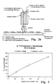
- FIG. 1 a detector-sample interface of a single channel of a detection system for epi-fluorescence measurements.
- a reading head may employ a single detection channel or may employ multiple detection channels, e.g. 12 or 96 channels.
- a single well with a thin transparent base containing a sample e.g. a solution of fluorophore or fluorescent labelled material such as cells
- a sample e.g. a solution of fluorophore or fluorescent labelled material such as cells
- the reading head comprises a bundle of optical fibres, which are a mixture of excitation and emission fibres.
- the excitation fibres convey wavelength-specific excitation light to the sample; the uniformity and efficiency of illumination are determined by the pattern of fibres, their numerical aperture and their distance from and registration with the base of the sample well. The efficiency of the emission fibres in gathering light from the well depends in a similar manner on these properties.
- the emission light is subsequently wavelength selected (at one or more wavelengths) using filters and passed to the detector.
- FIG. 1 two excitation light rays labelled E are shown.
- One of these produces a fluorescence event upon interaction with a fluorophore at any point in the sample volume, which results in a signal light ray which can be emitted in all directions.
- the signal ray S is received by an emission fibre of the reading head.
- the other excitation light ray undergoes reflection at the air/well base interface and is shown as being received as ray B by an emission fibre and is therefore a potential source of background light.
- a light ray E can strike any interface involving a change of refractive index, for example at the base of the plate or at the liquid/air interface at the top of the sample, and be reflected back into the detector.
- Excitation light entering the emission fibres can be accepted by the detector in a variety of ways.
- the excitation light has a different wavelength (generally shorter) than the signal light generated from the fluorophore
- such light rays can pass straight through the emission filters (typically interference or other band pass filters).
- the emission filters typically interference or other band pass filters.
- the excitation and emission wavelengths are typically 485 nm and 530 nm respectively.
- a further mechanism for excitation light to result in measurable background is the occurrence of large angle rays (e.g.
- excitation light captured by the emission fibres can pass through an emission interference filter (e.g. typically of effective refractive index 2) when the rays exit an emission fibre in a cone of half-angle of about 54 degrees which satisfies the transmission condition of the interference filter.
- an emission interference filter e.g. typically of effective refractive index 2
- a further source of background in this fluorescence type assay can result from fluorescence of materials other than the specific signal fluorophore, for example from the plate and the plate base, or materials used in the sample presentation matrix; from the sample medium (e.g. from proteins and other materials in the case of immunoassays and cell-based assays); and all components of the detection system itself, including the optical components such as filters, optical fibres, adhesives and other materials.
- Background produced by reflected light and detected, as described above, can be the dominant source of overall background in such epifluorescence assays.
- the variation and hence uncertainty in this background can therefore be a determining factor in the ultimate sensitivity and reproducibility of the assay.
- Other factors which can contribute to this variability include: scatter or reflections of the excitation light from the sample and the sample matrix which depend on sample matrix geometry; reflections from interfaces involving change in refractive index of medium; curvature or deformations of the sample presentation matrix, e.g. non-flatness of the sample plate and individual well bases which change the angular presentation and the stand-off of the sample from the reading head; errors in sample plate positioning over the reading head, both laterally (x. y) and vertically (z); variations in the transparency of the sample and the sample matrix, e.g. the well base; variations in the optics, geometry, positioning arid efficiency of channels, including channel to channel variations within the reading head.
- sample presentation format is a single or multi-well dish or plate, e.g. a microplate having an array of 96 (or multiples of 96 such as 384, 864, 1536, 2400, 3456, etc.) wells.
- a sample plate may contain liquid samples such as a solution of a fluorophore, an immunoassay complex, microparticles, or a suspension or monolayers of cells. Such a sample plate can be measured with the detection head either from above or from below the sample.
- a further example of a sample presentation is a membrane or gel containing, either within the matrix or its surface, an array of biological samples, e.g. DNA or proteins.
- a matrix is typically translucent and may be mounted on a solid support such as a glass plate. Again, this sample presentation may be measured from above or below, depending on the type of sample and the transparency of the matrix.
- Figures 2(a) and (b) show the case of reading a gel array or membrane from below and above respectively.
- a 96-channel reading head can measure simultaneously 96 wells of a sample plate, and wells of plates of higher multiples of 96 are read sequentially following lateral movements of the plate with respect to the reading head. For example a 1536 plate is read in 16 movements.
- the first stage is to take out variations common to a given type of sample presentation matrix, in this example a multi-well plate.
- a typical 96- or 384-well microplate typically has a downwards convex curvature of the base with magnitude corresponding to 150-300 micron displacement normal to the base between the centre and edge of the plate, which results in variation in the stand-off of wells with respect to their corresponding reading head.
- a suitable procedure is to take, e.g., 12 plates of the given type containing fluorophore sample and 12 containing sample medium such as buffer solution (buffer blank), each well containing the same voume of material. In the case of cells the corresponding signal samples and background media would be used. The signal from each well of each plate is then measured. The number of plates to be used is chosen to give a statistically significant result for the purpose of correction.
- This procedure reduces assay errors for signal and background to approximately 2-4% for multiple reading of different wells within the given type of plate, but leaves residual errors of this magnitude due to variations for a given well position from plate to plate, and errors within a given well positiion (e.g. flatness, dimpling or curvature of the well base which could amount to displacements of magnitude 25-75 microns, variations in sample meniscus, scratches and other defects).
- the effect of mechanical positioning errors in the loading and placement of plates with respect to the reading head can also be assessed. This comprises repeatedly loading and reading a given plate, e.g. 12 times, and observing the spread of results measured from this process in order to derive an error. This procedure can be repeated with different plates, which will also give an indication of sample delivery or pipetting errors. This makes it possible to determine the magnitude of these types of error with respect to sample matrix and channel errors described above.
- a further stage of correction is designed to minimise the residual errors decribed above, which will be dominated by random effects for a given well as between different plates. It will be recalled that these result from small variations (e.g. 2-4%) in the sample and presentation matrix including variations in flatness of a well (especially dimples or bowing, and deformations of the thin well base caused by wetting by the sample), scratches, and meniscus variations, and pipetting errors which change the volumes or amounts of sample material delivered to each well to vary.
- a plate is loaded with unknown samples, containing unknown amounts of fluorophore in a pre-determined volume. The sensitivity and precision of the assay is now determined by the magnitude of these residual errors and variations, mainly as they affect buffer blank.
- a further correction procedure with which the present invention is especially concerned therefore involves using a second wavelength range or ranges to illuminate and detect light from the samples being measured, so chosen to be off the peak wavelengths relevant to a given sample fluorophore being measured, so that it does not induce significant secondary fluorescence in the sample. This is achieved by appropriate choice of excitation and emission filters, outside the wavelength range of the assay.
- This procedure utilises the existing excitation and emission light paths in the detector, and by so doing the optical paths of illumination and light gathering are the same as for the specific assay sample measurement.
- the signals measured for each well will therefore represent the relative magnitude of the variations for each well, and hence can be used to derive correction factors, bringing each well onto an average value.
- buffer blank which as described above can be dominated by reflections from the well base and meniscus (which vary from well to well and plate to plate) will be mimicked by the measurement at the second wavelength.
- the influence of skew rays and their ability to penetrate the emission interference filter will be reproduced by choosing a ratio of excitation radiation wavelength to emission radiation wavelength similar to that of the actual assay.
- the specific values for fluorescein are 485/530 nm and the correction procedure may use wavelength 780/850 nm.
- Figure 4 shows a plot of loss signal with stand-off or displacement when the buffer blank sample is excited with 485 nm light, i.e. the sample excitation wavelength, and emitted radiation is detected at 530 nm.
- Figure 5 is shown a plot equivalent to that of Figure 4, obtained as an example with red light (780/830 nm). It can be seen that the same type of dependency of loss of signal with stand-off or displacement is obtained in the red as was obtained with the specific blue/green wavelength combination of Figure 4. This procedure also senses changes in sample volume in proportion with the specific wavelength. This demonstrates that relative correction factors, as between wells, can be obtained using light in a different wavelength band from that needed for the assay.
- UV excitation would most likely result in non-specific fluorescence from the sample and matrix and hence be unsuitable.
- the wavelengths selected for this correction procedure should however, in any case, be within the detection range or quantum efficiency of the detector being employed.
- the example given here utilises a cooled CCD, which has relatively high quantum efficiency in the red (30-40%) and even towards the IR, as compared to the blue/green range (5-15%). Wavelength ranges even up to approximately 1000 nm could therefore be used for this procedure, provided the optical detection system can pass these wavelengths.
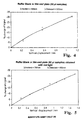
- wavelengths in the green such as 530/546, for which experimental data is shown in Figure 6.
- a still further example uses violet/blue light, such as 395/460 nm, for which experimental data is shown in Figure 7.
- wavelength combinations such as green/yellow or yellow/red may be used.
- the sample can contain fluorescent, chemiluminescent or bioluminescent labels or markers or dyes, or be a radioisotopic sample.
- the invention disclosed herein allows the error signals (equivalent to noise) generated in the detector inter alia by assay-plate imperfections and from the mere presence of buffer solution in the plate-wells, to be isolated from signals generated inter alia from light emission from the assay sample material, triggered by incident excitation wavelengths.
- the invention thus provides a technique for error signal determination which does not entail any changes being made to the liquid content of the wells, nor movement, nor cleaning of, the plate. This is achieved by changing the wavelength of the incident light for a calibration measurement so that little or no light emission from the assay sample material is triggered, and any light received by the detector can only arise from reflection, refraction, and imperfections etc. in the plate and/or buffer liquid inthe plate/well(s) under test. This can be used to correct both detected signals from light emitting assay sample material as well as background signals (i.e. detector output when no light emission from assay sample material is occurring).
- the calibration measurement may be performed before or after the assay is illuminated with excitation wavelength light, to allow the assay assessment to be made.
- the invention allows a very significant improvement in signal to noise level discrimination to be obtained, when detecting emitted light from low-light-level emitting assays, and for very low-light-level emitting assays to be monitored and much greater statistical certainty to be attributed to the light detector output.
- the light detector used to measure the light signals could be an imaging detector such as a charge coupled device (CCD), image intensifier or intensified CCD, or a single channel detector such as a photomultiplier tube (PMT) or photodiode.
- CCD charge coupled device
- PMT photomultiplier tube
- a different technique can be used to inhibit fluorescence. This can be done by introducing a light emission inhibitor using the same incident and detected wavelengths as used for the fluorescence examination of the sample, by first introducing a chemical reagent either in liquid or gaseous form, into the or each well, which has the effect of extinguishing or quenching or masking any light emission which would otherwise be emitted from the sample, in the presence of or following excitation wavelengths.
- radioisotope and/or chemiluminecent type assays a similar approach may be employed, using a suitable additive to extinguish mask or otherwise remove the light emission which is otherwise occurring.
Landscapes
- Health & Medical Sciences (AREA)
- Chemical & Material Sciences (AREA)
- Immunology (AREA)
- Physics & Mathematics (AREA)
- General Physics & Mathematics (AREA)
- Analytical Chemistry (AREA)
- Biochemistry (AREA)
- General Health & Medical Sciences (AREA)
- Life Sciences & Earth Sciences (AREA)
- Nuclear Medicine, Radiotherapy & Molecular Imaging (AREA)
- Pathology (AREA)
- Chemical Kinetics & Catalysis (AREA)
- Optics & Photonics (AREA)
- Investigating, Analyzing Materials By Fluorescence Or Luminescence (AREA)
- Investigating Or Analysing Biological Materials (AREA)
- Optical Measuring Cells (AREA)
Description
Claims (13)
- A method of performing a biomedical assay in which light is emitted by a sample or samples when excited by incident radiation in order to obtain an error corrected measurement signal, comprising the steps of:exciting the sample or samples along an excitation path with incident radiation of a given wavelength, thereby causing the sample to emit radiation of another wavelength transmitted along an emission path,measuring the quantity of light falling on a detector receiving the emitted radiation from the sample along the emission path, thereby to produce a first measurement,at a different time illuminating the sample or samples along the same excitation path with incident radiation of a different wavelength which does not cause the sample or samples to emit any significant radiation,detecting the quantity of light transmitted along the same emission path to fall on the same detector, thereby to produce a second measurement, andcorrecting the first measurement with respect to the second measurement, whereby to correct the first measurement in respect of errors, including errors inherent in the measurement system.
- A method according to claim 1, wherein the light of different wavelength lies in the infra-red region.
- A method according to claim 1, wherein the light of different wavelength lies in the ultra-violet region.
- A method according to any of claims 1 to 3, wherein the detector is a charge coupled device (CCD), an image intensifier, an intensified CCD, a cooled CCD, or a single channel detector such as a photomultiplier tube or photodiode.
- A method according to claim 4, wherein the different wavelength for obtaining the second measurement is higher than the excitation wavelength for the first measurement whilst remaining within the detection range and/or quantum efficiency of the detector.
- A method according to claim 1, wherein the different wavelength for the second measurement is 780 nm giving rise to substantially no emitted radiation from the sample or samples and detected at 830 nm.
- A method according to claim 1, wherein the different wavelength for the second measurement is 530 nm giving rise to substantially no emitted radiation from the sample or samples and detected at 546 nm.
- A method according to claim 1, wherein the different wavelength for the second measurement is 395 nm giving rise to substantially no emitted radiation from the sample or samples and detected at 460 nm.
- A method according to any of claims 1 to 8, wherein, when a multiple channel reading head reading a multiplicity of samples is employed, the first measurement is also corrected for variation in the stand-off of samples with respect to the reading head by averaging the first measurement over a plurality of the said multiplicity of samples.
- A method according to any of claims 1 to 9, wherein the first measurement is also corrected for mechanical positioning errors in the positioning of samples with respect to a reading head by reading the sample a plurality of times and deriving an error signal from the spread of resulting measurements.
- Apparatus for performing a biomedical assay in which light is emitted from a sample or samples when excited by incident radiation, comprising:means operative at different times respectively for illuminating the sample or samples along the same excitation path with incident radiation of two differing wavelengths, one of which does not cause the sample to emit any significant radiation,a detector for detecting the radiation emitted by the sample when illuminated at the two wavelengths, thereby to produce first and second measurements from the same detector, andmeans for correcting one measurement with respect to the other measurement.
- Apparatus according to claim 11, wherein the radiation incident on the sample or samples and the radiation emitted from the sample or samples is conveyed by a reading head having one or more channels and comprising for the or each channel a bundle of optical fibres which are a mixture of fibres for illumination light with fibres for receiving radiation to be detected.
- Apparatus according to claim 11 or claim 12, wherein the detecting means is a charge coupled device (CCD), an image intensifier, an intensified CCD, a cooled CCD, or a single channel detector such as a photomultiplier tube or photodiode.
Applications Claiming Priority (5)
| Application Number | Priority Date | Filing Date | Title |
|---|---|---|---|
| GBGB9806752.3A GB9806752D0 (en) | 1998-03-30 | 1998-03-30 | Biomedical assay error reduction |
| GB9806752 | 1998-03-30 | ||
| GB9807061 | 1998-04-02 | ||
| GBGB9807061.8A GB9807061D0 (en) | 1998-04-02 | 1998-04-02 | Improvements in and relating to biomedical assays |
| PCT/GB1999/000828 WO1999050648A1 (en) | 1998-03-30 | 1999-03-18 | Improvements in and relating to biomedical assays |
Publications (2)
| Publication Number | Publication Date |
|---|---|
| EP1068513A1 EP1068513A1 (en) | 2001-01-17 |
| EP1068513B1 true EP1068513B1 (en) | 2002-01-09 |
Family
ID=26313392
Family Applications (1)
| Application Number | Title | Priority Date | Filing Date |
|---|---|---|---|
| EP99910524A Expired - Lifetime EP1068513B1 (en) | 1998-03-30 | 1999-03-18 | Improvements in and relating to biomedical assays |
Country Status (6)
| Country | Link |
|---|---|
| US (1) | US6635886B1 (en) |
| EP (1) | EP1068513B1 (en) |
| JP (1) | JP2002510047A (en) |
| AU (1) | AU2945799A (en) |
| DE (1) | DE69900787T2 (en) |
| WO (1) | WO1999050648A1 (en) |
Cited By (1)
| Publication number | Priority date | Publication date | Assignee | Title |
|---|---|---|---|---|
| CN111044498A (en) * | 2019-12-26 | 2020-04-21 | 华中科技大学 | Fluorescent probe identification method, multicolor super-resolution localization imaging method and system |
Families Citing this family (12)
| Publication number | Priority date | Publication date | Assignee | Title |
|---|---|---|---|---|
| US20060013984A1 (en) * | 2003-09-19 | 2006-01-19 | Donald Sandell | Film preparation for seal applicator |
| US20050226780A1 (en) * | 2003-09-19 | 2005-10-13 | Donald Sandell | Manual seal applicator |
| US20060011305A1 (en) * | 2003-09-19 | 2006-01-19 | Donald Sandell | Automated seal applicator |
| US20060029948A1 (en) * | 2003-09-19 | 2006-02-09 | Gary Lim | Sealing cover and dye compatibility selection |
| US20050232818A1 (en) * | 2003-09-19 | 2005-10-20 | Donald Sandell | Single sheet seal applicator and cartridge |
| US20080006202A1 (en) * | 2006-06-26 | 2008-01-10 | Applera Corporation | Compressible transparent sealing for open microplates |
| JP5399250B2 (en) * | 2006-09-15 | 2014-01-29 | コーニング インコーポレイテッド | Optical interrogation system and microplate position correction method |
| GB201205607D0 (en) * | 2012-03-29 | 2012-05-16 | Ltd Technopath Distrib | A fluorescence microtitre plate reader |
| FR3000209B1 (en) * | 2012-12-26 | 2017-02-24 | Biomerieux Sa | METHOD AND SYSTEM FOR DETECTING AND MEASURING FLUORESCENCE SIGNALS |
| EP3267182B1 (en) * | 2015-03-02 | 2022-02-23 | Citizen Watch Co., Ltd. | Optical measuring device and toothbrush provided with same |
| EP3290905B1 (en) | 2016-09-05 | 2022-10-19 | F. Hoffmann-La Roche AG | Signal offset determination and correction |
| ES3031573T3 (en) * | 2020-03-26 | 2025-07-09 | Innovative Photonic Solutions Inc | Method for selection of raman excitation wavelengths in multi-source raman probe |
Family Cites Families (8)
| Publication number | Priority date | Publication date | Assignee | Title |
|---|---|---|---|---|
| US4100416A (en) | 1977-03-02 | 1978-07-11 | Block Engineering, Inc. | Serum fluorescence suppression |
| GB2043876A (en) | 1978-12-29 | 1980-10-08 | Coal Industry Patents Ltd | Determining Sulphur Content |
| US5040889A (en) * | 1986-05-30 | 1991-08-20 | Pacific Scientific Company | Spectrometer with combined visible and ultraviolet sample illumination |
| US5111821A (en) | 1988-11-08 | 1992-05-12 | Health Research, Inc. | Fluorometric method for detecting abnormal tissue using dual long-wavelength excitation |
| US5074306A (en) * | 1990-02-22 | 1991-12-24 | The General Hospital Corporation | Measurement of burn depth in skin |
| US5387527A (en) | 1992-06-26 | 1995-02-07 | Beckman Instruments, Inc. | Use of pH dependence for scatter correction in fluorescent methods |
| JP3224640B2 (en) | 1993-07-30 | 2001-11-05 | 三菱重工業株式会社 | Apparatus and method for measuring concentration by LIF |
| US5682038A (en) | 1995-04-06 | 1997-10-28 | Becton Dickinson And Company | Fluorescent-particle analyzer with timing alignment for analog pulse subtraction of fluorescent pulses arising from different excitation locations |
-
1999
- 1999-03-18 EP EP99910524A patent/EP1068513B1/en not_active Expired - Lifetime
- 1999-03-18 WO PCT/GB1999/000828 patent/WO1999050648A1/en not_active Ceased
- 1999-03-18 US US09/646,775 patent/US6635886B1/en not_active Expired - Fee Related
- 1999-03-18 AU AU29457/99A patent/AU2945799A/en not_active Abandoned
- 1999-03-18 JP JP2000541508A patent/JP2002510047A/en not_active Withdrawn
- 1999-03-18 DE DE69900787T patent/DE69900787T2/en not_active Expired - Lifetime
Cited By (1)
| Publication number | Priority date | Publication date | Assignee | Title |
|---|---|---|---|---|
| CN111044498A (en) * | 2019-12-26 | 2020-04-21 | 华中科技大学 | Fluorescent probe identification method, multicolor super-resolution localization imaging method and system |
Also Published As
| Publication number | Publication date |
|---|---|
| EP1068513A1 (en) | 2001-01-17 |
| US6635886B1 (en) | 2003-10-21 |
| DE69900787D1 (en) | 2002-02-28 |
| DE69900787T2 (en) | 2002-11-07 |
| WO1999050648A1 (en) | 1999-10-07 |
| AU2945799A (en) | 1999-10-18 |
| JP2002510047A (en) | 2002-04-02 |
Similar Documents
| Publication | Publication Date | Title |
|---|---|---|
| US6441894B1 (en) | Optical autofocus for use with microtiter plates | |
| US8659755B2 (en) | Luminescence reference standards | |
| US6466316B2 (en) | Apparatus and methods for spectroscopic measurements | |
| EP1681556B1 (en) | Imaging fluorescence signals using telecentricity | |
| US6635886B1 (en) | Biomedical assays | |
| US7551271B2 (en) | Uncaging devices | |
| US6985225B2 (en) | Fluorescence-measuring system | |
| US7199377B2 (en) | Optical analytic measurement device for fluorescence measurements in multisample carriers | |
| US20030030797A1 (en) | Solid state fluorescence and absorption spectroscopy | |
| US20040005243A1 (en) | Patterned supports for testing, evaluating and calibrating detection devices | |
| US8814427B2 (en) | Instrumentation and method for optical measurement of samples | |
| JP2004157018A (en) | Sensitivity calibration method for fluorescence detection device and fluorescence detection device | |
| GB2335978A (en) | Detecting the Background Noise of a Biomedical Assay | |
| US20020024018A1 (en) | Method of measuring phosphorescence or fluorescence | |
| JPH0372245A (en) | Measuring method and photometer for analyzing sample processed by fluorescent reagent | |
| EP0510175B1 (en) | Fluorescence assay apparatus | |
| EP1163497B1 (en) | Producing and measuring light and determining the amounts of analytes in microplate wells | |
| EP1681558B1 (en) | Imaging fluorescence signals using telecentric optics on the excitation and the imaging side |
Legal Events
| Date | Code | Title | Description |
|---|---|---|---|
| PUAI | Public reference made under article 153(3) epc to a published international application that has entered the european phase |
Free format text: ORIGINAL CODE: 0009012 |
|
| 17P | Request for examination filed |
Effective date: 20000928 |
|
| AK | Designated contracting states |
Kind code of ref document: A1 Designated state(s): DE FR |
|
| RAP1 | Party data changed (applicant data changed or rights of an application transferred) |
Owner name: PACKARD INSTRUMENT COMPANY |
|
| GRAG | Despatch of communication of intention to grant |
Free format text: ORIGINAL CODE: EPIDOS AGRA |
|
| 17Q | First examination report despatched |
Effective date: 20010417 |
|
| GRAG | Despatch of communication of intention to grant |
Free format text: ORIGINAL CODE: EPIDOS AGRA |
|
| GRAH | Despatch of communication of intention to grant a patent |
Free format text: ORIGINAL CODE: EPIDOS IGRA |
|
| GRAH | Despatch of communication of intention to grant a patent |
Free format text: ORIGINAL CODE: EPIDOS IGRA |
|
| GRAA | (expected) grant |
Free format text: ORIGINAL CODE: 0009210 |
|
| AK | Designated contracting states |
Kind code of ref document: B1 Designated state(s): DE FR |
|
| REF | Corresponds to: |
Ref document number: 69900787 Country of ref document: DE Date of ref document: 20020228 |
|
| ET | Fr: translation filed | ||
| PLBE | No opposition filed within time limit |
Free format text: ORIGINAL CODE: 0009261 |
|
| STAA | Information on the status of an ep patent application or granted ep patent |
Free format text: STATUS: NO OPPOSITION FILED WITHIN TIME LIMIT |
|
| 26N | No opposition filed | ||
| REG | Reference to a national code |
Ref country code: FR Ref legal event code: TP Ref country code: FR Ref legal event code: CD |
|
| PGFP | Annual fee paid to national office [announced via postgrant information from national office to epo] |
Ref country code: FR Payment date: 20130405 Year of fee payment: 15 Ref country code: DE Payment date: 20130327 Year of fee payment: 15 |
|
| REG | Reference to a national code |
Ref country code: DE Ref legal event code: R119 Ref document number: 69900787 Country of ref document: DE |
|
| REG | Reference to a national code |
Ref country code: FR Ref legal event code: ST Effective date: 20141128 |
|
| REG | Reference to a national code |
Ref country code: DE Ref legal event code: R119 Ref document number: 69900787 Country of ref document: DE Effective date: 20141001 |
|
| PG25 | Lapsed in a contracting state [announced via postgrant information from national office to epo] |
Ref country code: FR Free format text: LAPSE BECAUSE OF NON-PAYMENT OF DUE FEES Effective date: 20140331 Ref country code: DE Free format text: LAPSE BECAUSE OF NON-PAYMENT OF DUE FEES Effective date: 20141001 |