EP1068033B1 - Process for making a fluid-tight connection betweeen a tube and a plate-shaped part - Google Patents
Process for making a fluid-tight connection betweeen a tube and a plate-shaped part Download PDFInfo
- Publication number
- EP1068033B1 EP1068033B1 EP98924096A EP98924096A EP1068033B1 EP 1068033 B1 EP1068033 B1 EP 1068033B1 EP 98924096 A EP98924096 A EP 98924096A EP 98924096 A EP98924096 A EP 98924096A EP 1068033 B1 EP1068033 B1 EP 1068033B1
- Authority
- EP
- European Patent Office
- Prior art keywords
- tube
- plate
- hole
- shaped part
- mandrel
- Prior art date
- Legal status (The legal status is an assumption and is not a legal conclusion. Google has not performed a legal analysis and makes no representation as to the accuracy of the status listed.)
- Expired - Lifetime
Links
- 238000000034 method Methods 0.000 title claims description 21
- 230000008569 process Effects 0.000 title claims description 19
- 238000005219 brazing Methods 0.000 claims description 12
- 239000000463 material Substances 0.000 claims description 10
- XAGFODPZIPBFFR-UHFFFAOYSA-N aluminium Chemical compound [Al] XAGFODPZIPBFFR-UHFFFAOYSA-N 0.000 claims description 9
- 229910052782 aluminium Inorganic materials 0.000 claims description 9
- 239000004411 aluminium Substances 0.000 claims description 9
- 230000004907 flux Effects 0.000 claims description 6
- 238000010438 heat treatment Methods 0.000 claims description 6
- 229910000838 Al alloy Inorganic materials 0.000 claims description 4
- 230000007704 transition Effects 0.000 claims description 2
- 239000012530 fluid Substances 0.000 description 6
- 230000000694 effects Effects 0.000 description 4
- HCHKCACWOHOZIP-UHFFFAOYSA-N Zinc Chemical compound [Zn] HCHKCACWOHOZIP-UHFFFAOYSA-N 0.000 description 3
- 239000011701 zinc Substances 0.000 description 3
- 229910052725 zinc Inorganic materials 0.000 description 3
- 239000011248 coating agent Substances 0.000 description 2
- 238000000576 coating method Methods 0.000 description 2
- 238000003780 insertion Methods 0.000 description 2
- 230000037431 insertion Effects 0.000 description 2
- 229910000676 Si alloy Inorganic materials 0.000 description 1
- 238000004378 air conditioning Methods 0.000 description 1
- AZDRQVAHHNSJOQ-UHFFFAOYSA-N alumane Chemical group [AlH3] AZDRQVAHHNSJOQ-UHFFFAOYSA-N 0.000 description 1
- 238000000137 annealing Methods 0.000 description 1
- 239000000945 filler Substances 0.000 description 1
- 238000013021 overheating Methods 0.000 description 1
- 238000004080 punching Methods 0.000 description 1
- 238000007789 sealing Methods 0.000 description 1
- 239000007787 solid Substances 0.000 description 1
- 230000009466 transformation Effects 0.000 description 1
- 239000002699 waste material Substances 0.000 description 1
- XLYOFNOQVPJJNP-UHFFFAOYSA-N water Substances O XLYOFNOQVPJJNP-UHFFFAOYSA-N 0.000 description 1
Images
Classifications
-
- B—PERFORMING OPERATIONS; TRANSPORTING
- B21—MECHANICAL METAL-WORKING WITHOUT ESSENTIALLY REMOVING MATERIAL; PUNCHING METAL
- B21D—WORKING OR PROCESSING OF SHEET METAL OR METAL TUBES, RODS OR PROFILES WITHOUT ESSENTIALLY REMOVING MATERIAL; PUNCHING METAL
- B21D39/00—Application of procedures in order to connect objects or parts, e.g. coating with sheet metal otherwise than by plating; Tube expanders
- B21D39/08—Tube expanders
- B21D39/20—Tube expanders with mandrels, e.g. expandable
-
- B—PERFORMING OPERATIONS; TRANSPORTING
- B21—MECHANICAL METAL-WORKING WITHOUT ESSENTIALLY REMOVING MATERIAL; PUNCHING METAL
- B21D—WORKING OR PROCESSING OF SHEET METAL OR METAL TUBES, RODS OR PROFILES WITHOUT ESSENTIALLY REMOVING MATERIAL; PUNCHING METAL
- B21D39/00—Application of procedures in order to connect objects or parts, e.g. coating with sheet metal otherwise than by plating; Tube expanders
- B21D39/06—Application of procedures in order to connect objects or parts, e.g. coating with sheet metal otherwise than by plating; Tube expanders of tubes in openings, e.g. rolling-in
-
- Y—GENERAL TAGGING OF NEW TECHNOLOGICAL DEVELOPMENTS; GENERAL TAGGING OF CROSS-SECTIONAL TECHNOLOGIES SPANNING OVER SEVERAL SECTIONS OF THE IPC; TECHNICAL SUBJECTS COVERED BY FORMER USPC CROSS-REFERENCE ART COLLECTIONS [XRACs] AND DIGESTS
- Y10—TECHNICAL SUBJECTS COVERED BY FORMER USPC
- Y10T—TECHNICAL SUBJECTS COVERED BY FORMER US CLASSIFICATION
- Y10T29/00—Metal working
- Y10T29/49—Method of mechanical manufacture
- Y10T29/4935—Heat exchanger or boiler making
- Y10T29/49352—Repairing, converting, servicing or salvaging
-
- Y—GENERAL TAGGING OF NEW TECHNOLOGICAL DEVELOPMENTS; GENERAL TAGGING OF CROSS-SECTIONAL TECHNOLOGIES SPANNING OVER SEVERAL SECTIONS OF THE IPC; TECHNICAL SUBJECTS COVERED BY FORMER USPC CROSS-REFERENCE ART COLLECTIONS [XRACs] AND DIGESTS
- Y10—TECHNICAL SUBJECTS COVERED BY FORMER USPC
- Y10T—TECHNICAL SUBJECTS COVERED BY FORMER US CLASSIFICATION
- Y10T29/00—Metal working
- Y10T29/49—Method of mechanical manufacture
- Y10T29/4935—Heat exchanger or boiler making
- Y10T29/49373—Tube joint and tube plate structure
-
- Y—GENERAL TAGGING OF NEW TECHNOLOGICAL DEVELOPMENTS; GENERAL TAGGING OF CROSS-SECTIONAL TECHNOLOGIES SPANNING OVER SEVERAL SECTIONS OF THE IPC; TECHNICAL SUBJECTS COVERED BY FORMER USPC CROSS-REFERENCE ART COLLECTIONS [XRACs] AND DIGESTS
- Y10—TECHNICAL SUBJECTS COVERED BY FORMER USPC
- Y10T—TECHNICAL SUBJECTS COVERED BY FORMER US CLASSIFICATION
- Y10T29/00—Metal working
- Y10T29/53—Means to assemble or disassemble
- Y10T29/53113—Heat exchanger
- Y10T29/53122—Heat exchanger including deforming means
Definitions
- the invention relates to a process for making a fluid-tight connection between a tube and a plate-shaped part, comprising providing a hole in the plate-shaped part substantially corresponding to the cross-section of the tube, inserting one end of the tube into the hole, so that the tube end is partly extending beyond the surface of the plate-shaped part, and inserting a maudcel into said tube end.
- plate-shaped part such as e.g. used in heat exchangers.
- plate-shaped part any object having at least one portion which consisting of relatively thin wall with a substantially flat surface.
- tubes with at least one substantially flat surface such as headers in heat exchangers, box-like structures to be used as containers, such as gasoline tanks etc.
- the tube and / or the plate-shaped part are made out of aluminium or an aluminium -alloy.
- This type of material is especially effective in heat transfer applications and can be easily deformed at lower temperatures. Due to the spring-back effects from the mechanical deformation, it might be necessary to seal the tube to the plate shaped member by a more secure method, such as by using a brazing connection.
- brazing techniques for aluminium utilize Al:Si alloys for achieving a brazed joint, usually by use of clad sheet. This is a fairly high temperature operation, well above the temperature at which aluminium alloys become annaeled and softened. Therefor, heating of the whole of the assembly plate-shaped part and tube to effect a braze would soften the tube and the part so that deformation of the assembly is likely to occur under normal service conditions where high internal pressures can be encountered.
- Localized heating such as used when flame brazing is not feasible or is difficult to realize due to geometrical restrictions and the possibility of heat application outside the desired region.
- the plate-shaped or extruded part which is at least partly coated with a brazing and / or flux material.
- An advantageous coating material is zinc, allowing to reduce the temperature of the joining process substantially as zinc will melt and diffuse into the aluminium and form a reliable brazing material at low temperatures.
- the invention also relates to a process for making a fluid-tight connection between a header and a number of aluminium tubes coated with brazing and / or flux material, for making a heat exchanger, wherein the header at least comprises a member having a plate-shaped part.
- Heat exchanger of this tube requires a substantial number of connections to be made between a header and a number of tube ends in order to provide the flow channels. Obtaining a reliable fluid-tight connection between the header and the tube ends is still a cumbersome operation, and most failures in this type of heat exchanger occur at the connection between the tube ends and the header. This is partly due to the fact that connection place between the header and the tubes is difficult to reach as a result of the number of tubes and the fins already arranged around the tubes. This can result in unsound brazed joints.
- the transformation of the plate-shaped member into a header can be easily done either by deformation of the plate-shaped member so that a closed tube-like header is obtained which can easily and reliable be made fluid-tight by brazing, as the joint can be made at an easily accessible place. Otherwise it is possible to make the header by adding another unit to the plate-shaped member and sealing the connection edges between the member and the added unit, thereby providing a tube-like header.
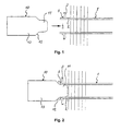
- Fig. 1 there is shown the end portion 2 of a tube 1 which should be connected in a fluid-tight manner to a plate-shaped part 3.
- the plate-shaped part 3 may be any wall-like portion of a unit to be used as fluid container or fluid transport conduct. The only requirement for the application of the invention is that both sides of the plate-shaped part are accessible for handling purposes as will be elucidated below.
- a hole 4 has been made in the plate-shaped part, which hole can be made in any conventional way.
- the dimensions of the tube end 2 and the hole 4 are selected in such a way that as seen in cross-section the shape of the hole 4 substantially corresponds to the shape of the tube end 2, while allowing some clearance between the tube end 2 and the hole 4 often the tube end 2 has been inserted in the hole 4.
- the tube end 2 is inserted into the hole 4 up to a defined depth and is temporarily fixed in this position by any suitable clamping means. While maintained in that position a mandrel 10 may be moved into the open end of tube 3.
- the expansion of the tube in order to give it a close contact with the fins can be performed simultaneously with the above cited expansion of the tube end.
- the mandrel 10 is fixed to any suitable moving means (not shown) suitable for inserting the mandrel 10 into the tube end 2 will sufficient force to generate the deformation to be obtained as explained below.
- the mandrel itself consists in fact of three parts, a first part or guiding part 11, a second of transition part 12 and a third or bay part 13.
- the guiding part 11 has a cross-section which is substantially equal to the internal cross-section of the tube end, in such a way that the free end portion (leading part) has dimensions which gradually increase toward its trailing part i.e. the part which is connected to the conical part 12.
- the dimensions of the cross-section gradually increase to dimensions such that the cross-section is larger than the cross-section of the tube end 2.
- the mandrel 10 can be made of material such as stud, and it may be completely solid, such as shown in Fig. 1, or it may be partly hollow, so that heating means can be incorporate inside the mandrel 10.
- the tube and the plate-shaped part are made out of aluminium or an aluminium alloy.
- the mandrel 10 may be heated, either directly by some suitable heating means provide inside the mandrel itself or its supporting means, or indirectly, i.e. the mandrel is preheated and its heat content is used during the insertion.
- a heated mandrel offers more over the possibility to generate a brazed connection between the tube end 2 and the edge 5 of the hole 4, especially in case aluminium parts are used.
- some brazing material must be present on the surface of at least one of the parts, i.e. either on the tube end 2, or on the hole edge 4 or on both.
- a filler to the aluminium surface of one or both parts, such as a zinc clad.
- the application of a flux may be superfluous as due to the mechanical deformation the oxyde - layer on the aluminium surface are cracked sufficiently to allow brazing . Otherwise it is also possible to apply a flux to one or both surfaces to be joined, in order to improve the joint.
Landscapes
- Engineering & Computer Science (AREA)
- Mechanical Engineering (AREA)
- Details Of Heat-Exchange And Heat-Transfer (AREA)
Description
The use of a heated mandrel, offers more over the possibility to generate a brazed connection between the
Claims (8)
- Process for making a fluid-tight connection between a tube (1) and a plate-shaped part (3), comprising providing a hole (4) in the plate-shaped part (3) substantially corresponding to the cross-section of the tube (1), inserting one end (2) of the tube (1) into the hole (4), so that the tube end (2) is partly extending beyond the surface of the plate-shaped part, and inserting a mandrel (10) into said tube end, characterized by said mandrel (10) comprising a first portion (11) having a cross-section substantially corresponding to the inner cross-section of the tube, a second portion (12) having an increased cross-section and a transition portion (12) between these two portions, maintaining the tube (1) in its inserted position while pressing the mandrel (10) into the inserted end (2) of the tube (1), and heating the mandrel (10) to a temperature at least sufficient to soften the tube material and maintaining this situation during a time sufficient to deform the tube en (2) on the plate-shaped part (3).
- Process according to claim 1,
characterized in that
the tube end / or the plate-shaped part are made out of aluminium or an aluminium alloy. - Process according to any one of the preceding claims,
characterized in that
at least the area around the hole and / or the tube is coated with a brazing and / or flux material. - process according to any one of the preceding claims,
characterized in that
the hole in the plate-shaped member is formed in such a way that an edge is formed around the hole. - Process according to claim 4, characterized in that the edge is oriented to the side of the plate-shaped member where the tube end is located.
- Process according to any one of the preceding claims, characterized in that before pressing the mandrel into the tube end, the tube is mechanically expanded in the hole.
- Process for making a fluid-tight connection between a header and a number of aluminium tubes coated with brazing and / or flux material, for making a heat exchanger, wherein the header at least comprises a member having a plate-shaped part,
characterized in that
the connection between each tube and the plate-shaped member is made in accordance to the process according to any one of the preceding claims, and that the member is subsequently modified into a header. - Process according to claim 7
characterized in that
the header is made out of at least two parts, a first part having a U-shaped cross-section and constituting the member, and a second part having a cross-section fitting over or in the first part, and in that after connecting the tubes to the first part the first part is closed in longitudinal direction by combining it to the second part and making a fluid-tight connection between these two parts.
Applications Claiming Priority (1)
| Application Number | Priority Date | Filing Date | Title |
|---|---|---|---|
| PCT/EP1998/001937 WO1999050004A1 (en) | 1998-03-31 | 1998-03-31 | Process for making a fluid-tight connection betweeen a tube and a plate-shaped part |
Publications (2)
| Publication Number | Publication Date |
|---|---|
| EP1068033A1 EP1068033A1 (en) | 2001-01-17 |
| EP1068033B1 true EP1068033B1 (en) | 2002-06-12 |
Family
ID=8166931
Family Applications (1)
| Application Number | Title | Priority Date | Filing Date |
|---|---|---|---|
| EP98924096A Expired - Lifetime EP1068033B1 (en) | 1998-03-31 | 1998-03-31 | Process for making a fluid-tight connection betweeen a tube and a plate-shaped part |
Country Status (5)
| Country | Link |
|---|---|
| US (1) | US6434824B1 (en) |
| EP (1) | EP1068033B1 (en) |
| AU (1) | AU7641698A (en) |
| DE (1) | DE69806070D1 (en) |
| WO (1) | WO1999050004A1 (en) |
Families Citing this family (4)
| Publication number | Priority date | Publication date | Assignee | Title |
|---|---|---|---|---|
| AT413343B (en) * | 2003-07-17 | 2006-02-15 | Dgs Druckguss Systeme Ag | METHOD FOR PRODUCING A LIGHTWEIGHT FUNCTION PART |
| JP4239840B2 (en) * | 2004-02-03 | 2009-03-18 | 株式会社デンソー | Mouth expansion jig for heat exchanger tubes |
| DE102013100885B4 (en) * | 2013-01-29 | 2020-02-27 | Benteler Automobiltechnik Gmbh | Heat exchangers for a motor vehicle |
| CN104259331B (en) * | 2014-07-31 | 2016-02-10 | 天津钢管集团股份有限公司 | The manufacture method of Φ 512mm × 37mm Hi-grade steel coupling blank |
Family Cites Families (14)
| Publication number | Priority date | Publication date | Assignee | Title |
|---|---|---|---|---|
| GB2095597B (en) * | 1981-03-28 | 1984-05-23 | Tryang Jig & Gauge The Co Ltd | Expanding solder rings in pipe fittings |
| DE3900744A1 (en) | 1989-01-12 | 1990-07-26 | Sueddeutsche Kuehler Behr | HEAT EXCHANGER |
| DE3908266A1 (en) * | 1989-03-14 | 1990-09-20 | Autokuehler Gmbh & Co Kg | HEAT EXCHANGER AND METHOD FOR FASTENING A LIQUID-TIGHT PLATE TO A HEAT EXCHANGER NET |
| US5150520A (en) * | 1989-12-14 | 1992-09-29 | The Allen Group Inc. | Heat exchanger and method of assembly thereof |
| US5117548A (en) * | 1991-05-20 | 1992-06-02 | The Babcock & Wilcox Company | Apparatus for loosening a mechanical plug in a heat exchanger tube |
| US6090072A (en) * | 1992-10-15 | 2000-07-18 | Scimed Life Systems, Inc. | Expandable introducer sheath |
| US5467818A (en) * | 1993-03-24 | 1995-11-21 | Valeo Climate Control Corporation | Heat exchanger |
| US5410800A (en) * | 1994-03-14 | 1995-05-02 | Carrier Corporation | Tube expander with rod support apparatus |
| US5806173A (en) * | 1995-07-28 | 1998-09-15 | Hidaka Seiki Kabushiki Kaisha | Tube expander |
| GB2328390B (en) * | 1997-08-23 | 2001-02-07 | Ford Motor Co | Improved bullet tube expanding apparatus |
| EP0922510B1 (en) * | 1997-12-10 | 2001-08-29 | ALSTOM Power (Schweiz) AG | Method and device for forming a tube in a tube plate |
| US6065664A (en) * | 1998-08-10 | 2000-05-23 | Thermal Corp. | Method of installing heat pipes using internal vapor pressure |
| US6138747A (en) * | 1999-02-17 | 2000-10-31 | Dehr Heat Transfer System, Inc. | Heat exchanger tube to header swaging process |
| US6183503B1 (en) * | 1999-09-17 | 2001-02-06 | Applied Medical Resources Corporation | Mesh stent with variable hoop strength |
-
1998
- 1998-03-31 EP EP98924096A patent/EP1068033B1/en not_active Expired - Lifetime
- 1998-03-31 DE DE69806070T patent/DE69806070D1/en not_active Expired - Lifetime
- 1998-03-31 WO PCT/EP1998/001937 patent/WO1999050004A1/en not_active Ceased
- 1998-03-31 AU AU76416/98A patent/AU7641698A/en not_active Abandoned
- 1998-03-31 US US09/647,225 patent/US6434824B1/en not_active Expired - Fee Related
Also Published As
| Publication number | Publication date |
|---|---|
| US6434824B1 (en) | 2002-08-20 |
| EP1068033A1 (en) | 2001-01-17 |
| DE69806070D1 (en) | 2002-07-18 |
| AU7641698A (en) | 1999-10-18 |
| WO1999050004A1 (en) | 1999-10-07 |
Similar Documents
| Publication | Publication Date | Title |
|---|---|---|
| TW552396B (en) | Heat exchanger and method of making the same | |
| US6061904A (en) | Heat exchanger and method for manufacturing the same | |
| JP3125834B2 (en) | Heat exchanger and method of manufacturing the same | |
| US6938675B2 (en) | Heat exchanger | |
| US5150520A (en) | Heat exchanger and method of assembly thereof | |
| EP0745823B1 (en) | Heat exchanger | |
| US5295302A (en) | Method of manufacturing an aluminum heat exchanger | |
| US6883600B2 (en) | Heat exchanger with dual heat-exchanging portions | |
| CA2308581C (en) | Method for assembling a heat exchanger | |
| MX2011003224A (en) | Method of forming aluminium heat exchangers header tanks. | |
| MXPA05005637A (en) | Thermal cycling resistant tube to header joint for heat exchangers. | |
| WO1996002348A1 (en) | Flat tube brazing method for laminated heat exchangers | |
| MXPA06010948A (en) | Heat exchanger having an improved baffle. | |
| US6434824B1 (en) | Process for making a fluid-tight connection between a tube and a plate-shaped part | |
| JP2006289481A (en) | Heat exchanger and manufacturing method thereof | |
| US5189900A (en) | Apparatus for connecting a coolant tube and header of a heat exchanger | |
| JPH033160B2 (en) | ||
| US5099575A (en) | Method for connecting a coolant tube and header of a heat exchanger | |
| JP2005127676A (en) | Heat exchanger and heat exchange manufacturing method | |
| JPH05277714A (en) | Heat exchanger manufacturing method | |
| EP4438988B1 (en) | The present invention relates to a heat exchanger, particularly, to a battery cooler for cooling batteries in electric vehicle | |
| JPH0557385A (en) | Manufacture of heat exchanger | |
| EP0840083A2 (en) | A baffle for a heat exchanger | |
| JPH08327284A (en) | Manufacture of multi-tube type heat exchanger | |
| KR100422897B1 (en) | Tube sheet joint type heat exchanger |
Legal Events
| Date | Code | Title | Description |
|---|---|---|---|
| PUAI | Public reference made under article 153(3) epc to a published international application that has entered the european phase |
Free format text: ORIGINAL CODE: 0009012 |
|
| 17P | Request for examination filed |
Effective date: 20000704 |
|
| AK | Designated contracting states |
Kind code of ref document: A1 Designated state(s): DE ES FR GB IT SE |
|
| GRAG | Despatch of communication of intention to grant |
Free format text: ORIGINAL CODE: EPIDOS AGRA |
|
| 17Q | First examination report despatched |
Effective date: 20010523 |
|
| GRAG | Despatch of communication of intention to grant |
Free format text: ORIGINAL CODE: EPIDOS AGRA |
|
| GRAH | Despatch of communication of intention to grant a patent |
Free format text: ORIGINAL CODE: EPIDOS IGRA |
|
| GRAH | Despatch of communication of intention to grant a patent |
Free format text: ORIGINAL CODE: EPIDOS IGRA |
|
| GRAA | (expected) grant |
Free format text: ORIGINAL CODE: 0009210 |
|
| AK | Designated contracting states |
Kind code of ref document: B1 Designated state(s): DE ES FR GB IT SE |
|
| PG25 | Lapsed in a contracting state [announced via postgrant information from national office to epo] |
Ref country code: IT Free format text: LAPSE BECAUSE OF FAILURE TO SUBMIT A TRANSLATION OF THE DESCRIPTION OR TO PAY THE FEE WITHIN THE PRE;WARNING: LAPSES OF ITALIAN PATENTS WITH EFFECTIVE DATE BEFORE 2007 MAY HAVE OCCURRED AT ANY TIME BEFORE 2007. THE CORRECT EFFECTIVE DATE MAY BE DIFFERENT FROM THE ONE RECORDED.SCRIBED TIME-LIMIT Effective date: 20020612 Ref country code: FR Free format text: LAPSE BECAUSE OF FAILURE TO SUBMIT A TRANSLATION OF THE DESCRIPTION OR TO PAY THE FEE WITHIN THE PRESCRIBED TIME-LIMIT Effective date: 20020612 |
|
| REG | Reference to a national code |
Ref country code: GB Ref legal event code: FG4D |
|
| REF | Corresponds to: |
Ref document number: 69806070 Country of ref document: DE Date of ref document: 20020718 |
|
| PG25 | Lapsed in a contracting state [announced via postgrant information from national office to epo] |
Ref country code: SE Free format text: LAPSE BECAUSE OF FAILURE TO SUBMIT A TRANSLATION OF THE DESCRIPTION OR TO PAY THE FEE WITHIN THE PRESCRIBED TIME-LIMIT Effective date: 20020912 |
|
| PG25 | Lapsed in a contracting state [announced via postgrant information from national office to epo] |
Ref country code: DE Free format text: LAPSE BECAUSE OF FAILURE TO SUBMIT A TRANSLATION OF THE DESCRIPTION OR TO PAY THE FEE WITHIN THE PRESCRIBED TIME-LIMIT Effective date: 20020913 |
|
| PG25 | Lapsed in a contracting state [announced via postgrant information from national office to epo] |
Ref country code: ES Free format text: LAPSE BECAUSE OF FAILURE TO SUBMIT A TRANSLATION OF THE DESCRIPTION OR TO PAY THE FEE WITHIN THE PRESCRIBED TIME-LIMIT Effective date: 20021220 |
|
| EN | Fr: translation not filed | ||
| PG25 | Lapsed in a contracting state [announced via postgrant information from national office to epo] |
Ref country code: GB Free format text: LAPSE BECAUSE OF NON-PAYMENT OF DUE FEES Effective date: 20030331 |
|
| PLBE | No opposition filed within time limit |
Free format text: ORIGINAL CODE: 0009261 |
|
| STAA | Information on the status of an ep patent application or granted ep patent |
Free format text: STATUS: NO OPPOSITION FILED WITHIN TIME LIMIT |
|
| 26N | No opposition filed |
Effective date: 20030313 |
|
| GBPC | Gb: european patent ceased through non-payment of renewal fee |
Effective date: 20030331 |