EP1067864B1 - Method and arrangement for determining where to position fixation means - Google Patents
Method and arrangement for determining where to position fixation means Download PDFInfo
- Publication number
- EP1067864B1 EP1067864B1 EP99917284A EP99917284A EP1067864B1 EP 1067864 B1 EP1067864 B1 EP 1067864B1 EP 99917284 A EP99917284 A EP 99917284A EP 99917284 A EP99917284 A EP 99917284A EP 1067864 B1 EP1067864 B1 EP 1067864B1
- Authority
- EP
- European Patent Office
- Prior art keywords
- femoral
- neck
- determining
- axis
- radiographs
- Prior art date
- Legal status (The legal status is an assumption and is not a legal conclusion. Google has not performed a legal analysis and makes no representation as to the accuracy of the status listed.)
- Expired - Lifetime
Links
Images

Classifications
-
- A—HUMAN NECESSITIES
- A61—MEDICAL OR VETERINARY SCIENCE; HYGIENE
- A61B—DIAGNOSIS; SURGERY; IDENTIFICATION
- A61B17/00—Surgical instruments, devices or methods, e.g. tourniquets
- A61B17/16—Bone cutting, breaking or removal means other than saws, e.g. Osteoclasts; Drills or chisels for bones; Trepans
- A61B17/17—Guides or aligning means for drills, mills, pins or wires
- A61B17/1721—Guides or aligning means for drills, mills, pins or wires for applying pins along or parallel to the axis of the femoral neck
-
- A—HUMAN NECESSITIES
- A61—MEDICAL OR VETERINARY SCIENCE; HYGIENE
- A61B—DIAGNOSIS; SURGERY; IDENTIFICATION
- A61B17/00—Surgical instruments, devices or methods, e.g. tourniquets
- A61B17/16—Bone cutting, breaking or removal means other than saws, e.g. Osteoclasts; Drills or chisels for bones; Trepans
- A61B17/17—Guides or aligning means for drills, mills, pins or wires
- A61B17/1703—Guides or aligning means for drills, mills, pins or wires using imaging means, e.g. by X-rays
-
- A—HUMAN NECESSITIES
- A61—MEDICAL OR VETERINARY SCIENCE; HYGIENE
- A61B—DIAGNOSIS; SURGERY; IDENTIFICATION
- A61B6/00—Apparatus for radiation diagnosis, e.g. combined with radiation therapy equipment
- A61B6/02—Devices for diagnosis sequentially in different planes; Stereoscopic radiation diagnosis
-
- A—HUMAN NECESSITIES
- A61—MEDICAL OR VETERINARY SCIENCE; HYGIENE
- A61B—DIAGNOSIS; SURGERY; IDENTIFICATION
- A61B6/00—Apparatus for radiation diagnosis, e.g. combined with radiation therapy equipment
- A61B6/12—Devices for detecting or locating foreign bodies
Definitions
- the present invention relates to a method and an arrangement determining where to position fixating means for hip fractures and an arrangement for providing attachment of said fixating means controlled by data from said method.
- a fixation of an injured leg is normally so firm that no movement will take place unless a substantial force is applied to the leg.
- Screws are inserted in order to fixate the fractured bone parts.
- the screws are introduced by a hand-held drill which opens up guide holes for the screws, whereby a surgeon has to judge the position of the drill from said two perpendicular radiographs and manually adjust the position of the drill in three dimensions, which is a very difficult task.
- Hip fractures belong to such a group, whereby about 18.000 incidents/year occur in Sweden alone, 9.000 cervical and 9.000 pertrochanteric, to a cost of approximately SEK 1.4 billions.
- ROBODOC® Surgical Assistant System A known arrangement to support surgery is the so-called ROBODOC® Surgical Assistant System.
- the ROBODOC® robot is able to precisely prepare a femoral channel for placement of a cementless prosthesis.
- the present invention generally relates to a method used for determining where to position fixating means in a hip fracture and an arrangement used to aid surgeons. It is controlled by data from said method. Said method brings about data out off conventional radiographs taken to detect fractures. Hence, the method is applied after diagnosis and before any medical treatment has taken place.
- the present invention provides a method for determining, in three dimensions, where to position fixating means in a hip fracture by pre-surgery analysis of at least one anteroposterior and one lateral digitized radiograph of said fracture. It comprises the following steps:
- femoral neck angels are displayed as lines and numerical values in said digitized graphs, said lines are automatically re-drawn if the value is changed.
- Another embodiment comprises that symbols for said fixating means are placed within the cross-section of the femoral neck.
- a still further embodiment includes a warning function, which is activated if said fixating means are placed outside the head or neck in said digitized radiographs.
- Fixating means for attachment are automatically displayed in said cross-sections with relation to made measurements according to one embodiment of the present invention.
- a still further embodiment provides means for putting down symbols for fixating means in the digitized radiographs.
- Yet another embodiment of the present invention comprises that said lines are regression lines drawn from at least three midpoints.
- the arrangement according to the present invention provides for attachment of fixating means in a hip fracture, through analyzing at least one anteroposterior and one lateral digitized radiographs of said fracture. It comprises:
- the femoral neck angels are displayed, by said means for displaying, as lines and numerical values in said digitized graphs, said lines are automatically re-drawn by graphic means if the value is changed.
- Another embodiment includes that symbols for said fixating means are placed within the cross-section of the femoral neck and displayed by said means for displaying.
- a further embodiment activates a warning function if said fixating means are placed outside of the femoral head or neck in said digitized radiographs.
- a still further embodiment includes that fixating means for attachment is automatically displayed in said graphs with relation to made measurements.
- Means are provided for putting down symbols for fixating means in the digitized radiographs in one embodiment of the present invention.
- Yet another embodiment of the present arrangement comprises that said lines are regression lines drawn from at least three midpoints.
- the present invention introduces a method specifically developed for the task.
- the method and arrangement, herein disclosed for hip fractures, are shown for purposes of illustration only and are not limiting of the present invention which is defined in the claims.
- said method provides means for storing digitized radiographs graphs from performed surgery and patient records in a database for quality checks and scientific research.
- the position of a pin or screw in relation to a construed femoral neck axis can be determined by measuring the distances from a discretionary point to a construed femoral neck axis, located at the same distance from the femoral head center in both the AP and lateral projections, to the pin or screw. The exact position is obtained if the following criteria are fulfilled:
- a reversed method i.e., it is determined where to place the pin or screw in the best possible way, is introduced through the present invention.
- the criteria nos. 1-3 can be fulfilled. This is time-consuming, however, and impracticable in routine examinations.
- routine radiographs of internally fixed femoral neck fractures the rotation of the hip varies in successive examinations and also in successive exposures, i.e. criteria nos. 1-3 above is not fulfilled.
- the rotated projections In order to determine the position of where to put pins/screws out off such radiographs, the rotated projections must be derotated to straight anterioposterior (AP) and lateral (Lat) projections. This is intuitively accomplished when a routine radiograph is interpreted, but this derotation is subjective and non-reproducible.
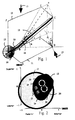
- FIG. 1 A femoral bone structure in perspective view marked up with symbols for mathematical calculation is schematically illustrated in Fig. 1.
- a method used for determining where fixating means have been placed after a performed surgery in hip fractures, derived from Fig. 1. is prior art, as stated above. Such a method was introduced and used by the inventor of the present invention in his study "Internal Fixation of Femoral Neck Fractures", Sweden 1993, ISBN 91-628-0804-4. Nevertheless, the method has been used only for post-surgery quality checks and scientific statistics, see “Quality of Reduction and Cortical Screw Support in Femoral Neck Fractures", by Stig Lindequist and Hans Törnkvist, Journal of Orthopaedic Trauma, Vol. 9, No. 3, pp. 215-221, 1995 Raven Press Ltd, New York.
- a reversed method according to the present invention can be used in determining how and where to drill in a femoral bone fracture in order to facilitate healing of said fracture in a best possible way.
- fixating means as for example screws
- the cortex the cortex
- fixating means are to be placed as adjacent to the femoral neck bone structure (the cortex)10 as possible, and centered in the femoral head 12 so that a fractured neck 10 can bear relatively heavy loads.
- Loads of 1500 N is common. This should be considered along with elderly peoples deteriorated content of marrow inside the bone structure, which emphasis the importance of the screws being placed adjacent to the cortex.
- the anteversion angle ⁇ is obtained by an assumed derotation of the proximal end of the femur to zero degree of anteversion in the AP and Lat projections. This derotation takes place along the femoral shaft axis 14 and with the lateral radiograph plate positioned along the femoral shaft. However, an assumed derotation of the proximal end of the femur to zero degree of anteversion in the AP and Lat projections can also take place along the femoral neck axis 16. This angle of derotation around the femoral neck axis 16 is defined as ⁇ .
- a pin placed along the femoral neck axis will also rotate ⁇ degrees.
- Fig. 1 further illustrates distances and angles OADG : Parallel to the film plane 11 in the AP projection 15; OAEF : Parallel to the film plane 13 in the lateral projection 17; OB : Central axis of the femoral neck 10; BC : Central axis of the femoral shaft 18; ⁇ : Cervicofemoral angel in the AP projection 15; ⁇ : Cervicofemoral angle in the lateral projection 17 when the central X-ray beams are perpendicular to the femoral neck axis 16; ⁇ o: Cervicofemoral angle in the lateral projection 17 when the central X-ray beams are not perpendicular to the femoral neck axis 10; ⁇ : The angle of inclination of the central X-ray beams in the lateral projection 17; ⁇ : The angle of deviation of the central X-ray beams in the lateral projection 17 from a direction perpendicular to the femoral neck axis 10; ⁇ : True fe
- the transformed co-ordinates X' and Y' in the femoral head 12 are plotted in a Cartesian co-ordinate system and circumscribed by a circle with the center placed at the origin of the co-ordinate system, and with the radius equal to that of the femoral head 12 at the measuring point.
- the obtained graph represents a cross-section of the femoral head at the level of the measuring point, as illustrated in Fig. 2 and Fig. 3 described below.
- the transformed co-ordinates X'and Y' are plotted in a co-ordinate system and circumscribed by cross-section graphs of the femoral neck 10.
- PINTRACE TM a known method named PINTRACE TM has been adapted and developed, to suggest screw positions, in said femoral neck axis 10 and said femoral shaft axis 14 in the AP and Lat radiographs instead of only analyzing already applied screws.
- the known older method PINTRACE TM was developed by the same inventor as for the present invention and referred to in his thesis "Internal Fixation of Femoral Neck Fractures" , Sweden 1993, ISBN 91-628-0804-4.
- the positions of inserted fixating pins/screws are calculated and presented in constructed cross-sections of the femoral neck 10 and head 12.
- an entirely new PINTRACE TM method was developed.
- the common part between the old known PINTRACE TM and the new PINTRACE TM method is that the configuration according to Fig. 1 is provided in order to make necessary calculations possible.
- the new PINTRACE TM method is a sub-method to the method of the present invention where the shape of the femoral neck 10 and head 12 are determined, constructed and displayed on, for example, a computer screen as empty cross-section graphs.
- placing symbols is a dynamic task, which varies among patients considering the importance of placing pins/screws as adjacent to the cortex as possible. Positions of provided symbols are transferred to the digitized AP and Lat radiographs and overlaid on these in form of colored lines of varying thickness.
- the user can change the calculated standard radii if they differ from the measured radii on the film in question.
- Fig. 2 illustrates a cross-section of a dislocated hip fracture displaying symbols for fixating means, here screws indicated by broken lines and filled circles, according to the present invention.
- FIG. 2 The cross-section view in Fig. 2 of caput 12 (femoral head) and collum femoris 10 (femoral neck) shows a dislocated hip fracture with two screws attached.
- Filled black circles 20 represent the position of said screws in collum femoris 10
- filled white circles represent the position of screws in caput 12.
- Adjacent circles 24, 26 indicate a specific degree of uncertainty for marked up screw positions.
- Fig. 3 illustrates a cross section of a non-dislocated hip fracture displaying symbols for fixating means, here screws indicated by broken lines and filled circles, according to the present invention.
- FIG. 3 of caput 12 and collum femoris 10 shows a non-dislocated hip fracture with two screws attached.
- Filled black circles 20 represent the position of said screws in collum femoris 10
- filled white circles represent the position of screws in caput 12.
- Adjacent circles 24, 26 indicate a specific degree of uncertainty for marked up screw positions.
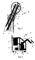
- Fig. 4 illustrates a femoral bone structure 30 from its anteroposterior projection 15 with two marked screws 32 according to the present invention.
- Fig. 5 illustrates a femoral bone structure 30 from its lateral projection 17 with two marked screws 32 according to the present invention.
- the central axes 14, 16 of the femoral neck 10 and shaft 18 are marked and the femoral neck-angles ⁇ and ⁇ are measured.
- the distance from the femoral neck axis 16 to a marker which indicates where to position a screw 32, when surgery is performed, at one measuring points in the Lat view 17 is taken to represent the X co-ordinate and the distance in the AP view 15 the Y co-ordinate for the pin.
- Angles as shown in Fig. 1, Fig. 4 and Fig. 5 are used to place the femoral bone structure 30 in space, thus finally indicating the direction for insertion of screws 32.
- Co-ordinates in the inferior or posterior halves of the femoral head 12 and neck 10 are assigned negative values, see Fig. 2 and Fig. 3.
- the point of intersection of the femoral head sphere and the femoral neck axis 16 is used as measuring point.
- the diameters 34, 35, indicated by broken lines in figures 4 and 5, of the femoral head 12 and neck 10 are determined at the measuring points in both the AP and Lat projections 15, 17.
- the present invention provides a method for determining, in three dimensions, where to position fixating means in a hip fracture by pre-surgery analysis of at least one anteroposterior and one lateral digitized radiograph of said fracture. It comprises the following steps:
- Femoral neck-/shaft-angels ⁇ , ⁇ are preferably displayed both as lines and as numerical values in said digitized graphs, said lines are automatically re-drawn if the value is changed.
- Lines in the present invention are possible to determine with two midpoints, but it should be understood that a more exact line is obtained by drawing a regression line from at least three midpoints on said axes.
- Symbols 20, 22 for said fixating means are placed within the cross-section of the femoral neck 10 and a warning function is activated if said fixating means are placed outside of the femoral head 12 or neck 10 in said digitized radiographs.
- Fixating means 32 for attachment are automatically displayed in said graphs, through graphical means known per se, with relation to made measurements. Also, it is possible to put down symbols 20, 22 for fixating means 32 in the digitized radiographs.
- radiographs are analyzed before any surgical treatment, and measured and computed values can be applied as control input to an arrangement 40 which accomplishes insertion guides, holes for example, for bone fracture fixating means 32, said arrangement 40 being described below.
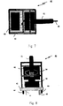
- Fig. 6 illustrates a side view elevation of an arrangement 40 according to the present invention
- Fig. 7 illustrates a top plan view of an arrangement 40 according to the present invention.
- Fig. 8 illustrates a front view elevation of an arrangement 40 according to the present invention.
- the arrangement 40 according to the embodiment schematically shown in figures 6-8 is a robot on a mobile stand 42 attached with wheels 44 and adjustable feet such as bars, poles 46 or the like for stabilization when ever needed.
- a control box 48 with a cable link 50 connected to an articulated robot arm 52 with servo or stepper motors 54.
- a transformer 56 distributes power.
- the control box 48 is adapted to be connected to peripheral equipment such as a computer with I/O ports for control and communication, a display device, a printer, scanner, frame grabber, and other known computer equipment.
- a tool holder 58 attached on the robot arm 52 is a tool holder 58, for example, used to hold a drilling-machine.
- control box 48 for controlling the robot contains hardware devices, firmware devices and software controlled by a processor, each device known per se, but forming an unique entity for applications according to the present invention.
- measurement means/function can be composed of multiple means, or integrated into one or more means/function as described below according to the present invention.
- the device comprises a plexiglass plate with four lead balls attached and placed in a square pattern. While trans-illuminating in the AP and Lat projections in parallel with the ball pattern, two balls are adjusted to be placed in the center of the radiation field so that they cover each other entirely. Thus, through measuring the distance between the two balls left, an absolute measure of the distortion is determined (the magnification ratio) provided that a predetermined distance between the radiation tube and the plexiglass plate is upheld. This distance corresponds to the working distance when distance determinations are made. A calculation in percentage to adjust the robot arm is finally applied.
- Femoral neck angels ⁇ , ⁇ are displayed by said display as lines and numerical values in said digitized graphs.
- the lines are automatically re-drawn, preferably controlled through software and/or graphic means, if the value is changed.
- Symbols 20, 24 for said fixating means are placed within the cross-section of the femoral neck and displayed by said display.
- fixating means 32 It is included a device or function that activates a warning function if fixating means 32 are placed outside the femoral head or neck in said digitized radiographs.
- fixating means for attachment are automatically displayed in said digitized radiographs with relation to made measurements, by software.
- Means such as graphic drivers, can be provided for putting down symbols for fixating means 20, 24, 32 in the digitized radiographs of the present invention.
- the method as herein described is preferably applied to control the robot in using its tool to work in the right direction, and prepare for insertion of fixating means such as screws, pins, nails, etc.
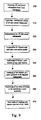
- FIG. 9 illustrates a flow chart depicting steps 900 to 980, taken in the method of the present invention, which is applied as control information to an arrangement.
- AP and Lat radiographs from C-arm fluoroscopy are obtained.
- the radiographs are digitized, rotated and scaled 910, by drivers for that purpose, followed by performing 920 necessary measurement operations, with means or functions described above, on the radiographs of a hip fracture.
- Made measurements are resulting in construction 930, through a software, of femoral neck and head cross-section graphs, which are displayed on a screen. Displayed cross-sections are marked 940 with pin/screw markers, which are changeable through software. An outlining 950 of the marked pin/screw positions in the digitized radiographs is thus performed.
- the steps 900-950 are applied to position 960 a robot to drill in said positions. This is followed up by a final check of determined positions. Eventually, during surgery, a surgeon manually inserts 980 pins/screws.
Applications Claiming Priority (3)
| Application Number | Priority Date | Filing Date | Title |
|---|---|---|---|
| SE9801168 | 1998-04-01 | ||
| SE9801168A SE510968C2 (sv) | 1998-04-01 | 1998-04-01 | Förfarande och anordning för bestämning av positionen hos fixeringsorgan vid höftledsfraktur |
| PCT/SE1999/000522 WO1999049786A1 (en) | 1998-04-01 | 1999-03-30 | Method and arrangement for determining where to position fixation means |
Publications (2)
| Publication Number | Publication Date |
|---|---|
| EP1067864A1 EP1067864A1 (en) | 2001-01-17 |
| EP1067864B1 true EP1067864B1 (en) | 2004-05-12 |
Family
ID=20410842
Family Applications (1)
| Application Number | Title | Priority Date | Filing Date |
|---|---|---|---|
| EP99917284A Expired - Lifetime EP1067864B1 (en) | 1998-04-01 | 1999-03-30 | Method and arrangement for determining where to position fixation means |
Country Status (12)
| Country | Link |
|---|---|
| US (1) | US6567681B1 (sv) |
| EP (1) | EP1067864B1 (sv) |
| JP (1) | JP4025508B2 (sv) |
| KR (1) | KR20010042379A (sv) |
| CN (1) | CN1303248A (sv) |
| AT (1) | ATE266357T1 (sv) |
| AU (1) | AU3543899A (sv) |
| CA (1) | CA2369039A1 (sv) |
| DE (1) | DE69917244T2 (sv) |
| IL (1) | IL138673A0 (sv) |
| SE (1) | SE510968C2 (sv) |
| WO (1) | WO1999049786A1 (sv) |
Families Citing this family (88)
| Publication number | Priority date | Publication date | Assignee | Title |
|---|---|---|---|---|
| NO20011275L (no) * | 2001-03-13 | 2002-09-16 | Bjoern Franc Iversen | System for å tilveiebringe informasjon om resultatet etter innsetting av protese i hofteledd |
| FR2871363B1 (fr) * | 2004-06-15 | 2006-09-01 | Medtech Sa | Dispositif robotise de guidage pour outil chirurgical |
| US9345548B2 (en) | 2006-02-27 | 2016-05-24 | Biomet Manufacturing, Llc | Patient-specific pre-operative planning |
| US9918740B2 (en) | 2006-02-27 | 2018-03-20 | Biomet Manufacturing, Llc | Backup surgical instrument system and method |
| US8298237B2 (en) | 2006-06-09 | 2012-10-30 | Biomet Manufacturing Corp. | Patient-specific alignment guide for multiple incisions |
| US8568487B2 (en) | 2006-02-27 | 2013-10-29 | Biomet Manufacturing, Llc | Patient-specific hip joint devices |
| US8070752B2 (en) | 2006-02-27 | 2011-12-06 | Biomet Manufacturing Corp. | Patient specific alignment guide and inter-operative adjustment |
| US8407067B2 (en) | 2007-04-17 | 2013-03-26 | Biomet Manufacturing Corp. | Method and apparatus for manufacturing an implant |
| US8473305B2 (en) | 2007-04-17 | 2013-06-25 | Biomet Manufacturing Corp. | Method and apparatus for manufacturing an implant |
| US8608748B2 (en) | 2006-02-27 | 2013-12-17 | Biomet Manufacturing, Llc | Patient specific guides |
| US9339278B2 (en) | 2006-02-27 | 2016-05-17 | Biomet Manufacturing, Llc | Patient-specific acetabular guides and associated instruments |
| US8282646B2 (en) | 2006-02-27 | 2012-10-09 | Biomet Manufacturing Corp. | Patient specific knee alignment guide and associated method |
| US8092465B2 (en) | 2006-06-09 | 2012-01-10 | Biomet Manufacturing Corp. | Patient specific knee alignment guide and associated method |
| US9907659B2 (en) | 2007-04-17 | 2018-03-06 | Biomet Manufacturing, Llc | Method and apparatus for manufacturing an implant |
| US8133234B2 (en) | 2006-02-27 | 2012-03-13 | Biomet Manufacturing Corp. | Patient specific acetabular guide and method |
| US7967868B2 (en) | 2007-04-17 | 2011-06-28 | Biomet Manufacturing Corp. | Patient-modified implant and associated method |
| US8535387B2 (en) | 2006-02-27 | 2013-09-17 | Biomet Manufacturing, Llc | Patient-specific tools and implants |
| US9113971B2 (en) | 2006-02-27 | 2015-08-25 | Biomet Manufacturing, Llc | Femoral acetabular impingement guide |
| US8603180B2 (en) | 2006-02-27 | 2013-12-10 | Biomet Manufacturing, Llc | Patient-specific acetabular alignment guides |
| US8591516B2 (en) | 2006-02-27 | 2013-11-26 | Biomet Manufacturing, Llc | Patient-specific orthopedic instruments |
| US9173661B2 (en) | 2006-02-27 | 2015-11-03 | Biomet Manufacturing, Llc | Patient specific alignment guide with cutting surface and laser indicator |
| US10278711B2 (en) | 2006-02-27 | 2019-05-07 | Biomet Manufacturing, Llc | Patient-specific femoral guide |
| US8377066B2 (en) | 2006-02-27 | 2013-02-19 | Biomet Manufacturing Corp. | Patient-specific elbow guides and associated methods |
| US8858561B2 (en) | 2006-06-09 | 2014-10-14 | Blomet Manufacturing, LLC | Patient-specific alignment guide |
| US8864769B2 (en) | 2006-02-27 | 2014-10-21 | Biomet Manufacturing, Llc | Alignment guides with patient-specific anchoring elements |
| US9289253B2 (en) | 2006-02-27 | 2016-03-22 | Biomet Manufacturing, Llc | Patient-specific shoulder guide |
| US20150335438A1 (en) | 2006-02-27 | 2015-11-26 | Biomet Manufacturing, Llc. | Patient-specific augments |
| US20080257363A1 (en) * | 2007-04-17 | 2008-10-23 | Biomet Manufacturing Corp. | Method And Apparatus For Manufacturing An Implant |
| US8241293B2 (en) | 2006-02-27 | 2012-08-14 | Biomet Manufacturing Corp. | Patient specific high tibia osteotomy |
| US8608749B2 (en) | 2006-02-27 | 2013-12-17 | Biomet Manufacturing, Llc | Patient-specific acetabular guides and associated instruments |
| US20070233103A1 (en) * | 2006-03-31 | 2007-10-04 | Metzinger Anthony J | Intramedullary nail, intramedullary nail assembly and method |
| US20070233102A1 (en) * | 2006-03-31 | 2007-10-04 | Metzinger Anthony J | Variable angle fixture, kit and method of presetting a nail assembly |
| US9795399B2 (en) | 2006-06-09 | 2017-10-24 | Biomet Manufacturing, Llc | Patient-specific knee alignment guide and associated method |
| US8265949B2 (en) | 2007-09-27 | 2012-09-11 | Depuy Products, Inc. | Customized patient surgical plan |
| US8425523B2 (en) | 2007-09-30 | 2013-04-23 | DePuy Synthes Products, LLC | Customized patient-specific instrumentation for use in orthopaedic surgical procedures |
| US8357111B2 (en) | 2007-09-30 | 2013-01-22 | Depuy Products, Inc. | Method and system for designing patient-specific orthopaedic surgical instruments |
| US8170641B2 (en) | 2009-02-20 | 2012-05-01 | Biomet Manufacturing Corp. | Method of imaging an extremity of a patient |
| GB0911697D0 (en) * | 2009-07-06 | 2009-08-19 | Smith & Nephew | Methods and devices for monitoring fractures |
| DE102009028503B4 (de) | 2009-08-13 | 2013-11-14 | Biomet Manufacturing Corp. | Resektionsschablone zur Resektion von Knochen, Verfahren zur Herstellung einer solchen Resektionsschablone und Operationsset zur Durchführung von Kniegelenk-Operationen |
| US8632547B2 (en) | 2010-02-26 | 2014-01-21 | Biomet Sports Medicine, Llc | Patient-specific osteotomy devices and methods |
| US9066727B2 (en) | 2010-03-04 | 2015-06-30 | Materialise Nv | Patient-specific computed tomography guides |
| WO2011158117A2 (en) | 2010-06-16 | 2011-12-22 | A2 Surgical | Method and system of automatic determination of geometric elements characterizing a bone deformation from 3d image |
| US8965108B2 (en) * | 2010-06-16 | 2015-02-24 | A2 Surgical | Method and system of automatic determination of geometric elements from a 3D medical image of a bone |
| US9271744B2 (en) | 2010-09-29 | 2016-03-01 | Biomet Manufacturing, Llc | Patient-specific guide for partial acetabular socket replacement |
| DE102010061777B4 (de) * | 2010-11-23 | 2019-08-14 | Siemens Healthcare Gmbh | Verfahren zur Bestimmung eines Parameters eines Fixierelementes für ein an einem Knochen zu fixierendes Implantat |
| US9968376B2 (en) | 2010-11-29 | 2018-05-15 | Biomet Manufacturing, Llc | Patient-specific orthopedic instruments |
| US9241745B2 (en) | 2011-03-07 | 2016-01-26 | Biomet Manufacturing, Llc | Patient-specific femoral version guide |
| CN102151141A (zh) * | 2011-03-29 | 2011-08-17 | 中国人民解放军第三军医大学第一附属医院 | 股骨头颈空间角度的测量方法 |
| US8715289B2 (en) | 2011-04-15 | 2014-05-06 | Biomet Manufacturing, Llc | Patient-specific numerically controlled instrument |
| US9675400B2 (en) | 2011-04-19 | 2017-06-13 | Biomet Manufacturing, Llc | Patient-specific fracture fixation instrumentation and method |
| US8956364B2 (en) | 2011-04-29 | 2015-02-17 | Biomet Manufacturing, Llc | Patient-specific partial knee guides and other instruments |
| US8668700B2 (en) | 2011-04-29 | 2014-03-11 | Biomet Manufacturing, Llc | Patient-specific convertible guides |
| US8532807B2 (en) | 2011-06-06 | 2013-09-10 | Biomet Manufacturing, Llc | Pre-operative planning and manufacturing method for orthopedic procedure |
| US9084618B2 (en) | 2011-06-13 | 2015-07-21 | Biomet Manufacturing, Llc | Drill guides for confirming alignment of patient-specific alignment guides |
| US20130001121A1 (en) | 2011-07-01 | 2013-01-03 | Biomet Manufacturing Corp. | Backup kit for a patient-specific arthroplasty kit assembly |
| US8764760B2 (en) | 2011-07-01 | 2014-07-01 | Biomet Manufacturing, Llc | Patient-specific bone-cutting guidance instruments and methods |
| US8597365B2 (en) | 2011-08-04 | 2013-12-03 | Biomet Manufacturing, Llc | Patient-specific pelvic implants for acetabular reconstruction |
| US9295497B2 (en) | 2011-08-31 | 2016-03-29 | Biomet Manufacturing, Llc | Patient-specific sacroiliac and pedicle guides |
| US9066734B2 (en) | 2011-08-31 | 2015-06-30 | Biomet Manufacturing, Llc | Patient-specific sacroiliac guides and associated methods |
| US9386993B2 (en) | 2011-09-29 | 2016-07-12 | Biomet Manufacturing, Llc | Patient-specific femoroacetabular impingement instruments and methods |
| US9301812B2 (en) | 2011-10-27 | 2016-04-05 | Biomet Manufacturing, Llc | Methods for patient-specific shoulder arthroplasty |
| US9554910B2 (en) | 2011-10-27 | 2017-01-31 | Biomet Manufacturing, Llc | Patient-specific glenoid guide and implants |
| US9451973B2 (en) | 2011-10-27 | 2016-09-27 | Biomet Manufacturing, Llc | Patient specific glenoid guide |
| KR20130046336A (ko) | 2011-10-27 | 2013-05-07 | 삼성전자주식회사 | 디스플레이장치의 멀티뷰 디바이스 및 그 제어방법과, 디스플레이 시스템 |
| ES2635542T3 (es) | 2011-10-27 | 2017-10-04 | Biomet Manufacturing, Llc | Guías glenoideas específicas para el paciente |
| US9237950B2 (en) | 2012-02-02 | 2016-01-19 | Biomet Manufacturing, Llc | Implant with patient-specific porous structure |
| US9060788B2 (en) | 2012-12-11 | 2015-06-23 | Biomet Manufacturing, Llc | Patient-specific acetabular guide for anterior approach |
| US9204977B2 (en) | 2012-12-11 | 2015-12-08 | Biomet Manufacturing, Llc | Patient-specific acetabular guide for anterior approach |
| US9839438B2 (en) | 2013-03-11 | 2017-12-12 | Biomet Manufacturing, Llc | Patient-specific glenoid guide with a reusable guide holder |
| US9579107B2 (en) | 2013-03-12 | 2017-02-28 | Biomet Manufacturing, Llc | Multi-point fit for patient specific guide |
| US9498233B2 (en) | 2013-03-13 | 2016-11-22 | Biomet Manufacturing, Llc. | Universal acetabular guide and associated hardware |
| US9826981B2 (en) | 2013-03-13 | 2017-11-28 | Biomet Manufacturing, Llc | Tangential fit of patient-specific guides |
| US9517145B2 (en) | 2013-03-15 | 2016-12-13 | Biomet Manufacturing, Llc | Guide alignment system and method |
| US20150112349A1 (en) | 2013-10-21 | 2015-04-23 | Biomet Manufacturing, Llc | Ligament Guide Registration |
| US10282488B2 (en) | 2014-04-25 | 2019-05-07 | Biomet Manufacturing, Llc | HTO guide with optional guided ACL/PCL tunnels |
| US9408616B2 (en) | 2014-05-12 | 2016-08-09 | Biomet Manufacturing, Llc | Humeral cut guide |
| US9839436B2 (en) | 2014-06-03 | 2017-12-12 | Biomet Manufacturing, Llc | Patient-specific glenoid depth control |
| US9561040B2 (en) | 2014-06-03 | 2017-02-07 | Biomet Manufacturing, Llc | Patient-specific glenoid depth control |
| US9826994B2 (en) | 2014-09-29 | 2017-11-28 | Biomet Manufacturing, Llc | Adjustable glenoid pin insertion guide |
| US9833245B2 (en) | 2014-09-29 | 2017-12-05 | Biomet Sports Medicine, Llc | Tibial tubercule osteotomy |
| US9820868B2 (en) | 2015-03-30 | 2017-11-21 | Biomet Manufacturing, Llc | Method and apparatus for a pin apparatus |
| US10568647B2 (en) | 2015-06-25 | 2020-02-25 | Biomet Manufacturing, Llc | Patient-specific humeral guide designs |
| US10226262B2 (en) | 2015-06-25 | 2019-03-12 | Biomet Manufacturing, Llc | Patient-specific humeral guide designs |
| US11925420B2 (en) | 2015-08-05 | 2024-03-12 | Accupredict, Inc. | Adjustment system and method for patient position intraoperatively using radiographic measurements |
| KR101696842B1 (ko) * | 2015-09-24 | 2017-01-17 | 서강대학교산학협력단 | 고관절 전치환술을 위한 인공기관의 넥 설계방법 및 상기 설계방법에 의해서 제작되는 인공기관 |
| US10722310B2 (en) | 2017-03-13 | 2020-07-28 | Zimmer Biomet CMF and Thoracic, LLC | Virtual surgery planning system and method |
| US11051829B2 (en) | 2018-06-26 | 2021-07-06 | DePuy Synthes Products, Inc. | Customized patient-specific orthopaedic surgical instrument |
| EP4351446A1 (en) * | 2021-06-11 | 2024-04-17 | Accupredict, Inc. | Adjustment system and method for patient position intraoperatively using radiographic measurements |
Family Cites Families (2)
| Publication number | Priority date | Publication date | Assignee | Title |
|---|---|---|---|---|
| US5772594A (en) * | 1995-10-17 | 1998-06-30 | Barrick; Earl F. | Fluoroscopic image guided orthopaedic surgery system with intraoperative registration |
| US6285902B1 (en) * | 1999-02-10 | 2001-09-04 | Surgical Insights, Inc. | Computer assisted targeting device for use in orthopaedic surgery |
-
1998
- 1998-04-01 SE SE9801168A patent/SE510968C2/sv not_active IP Right Cessation
-
1999
- 1999-03-30 AU AU35438/99A patent/AU3543899A/en not_active Abandoned
- 1999-03-30 IL IL13867399A patent/IL138673A0/xx unknown
- 1999-03-30 CN CN99806876A patent/CN1303248A/zh active Pending
- 1999-03-30 KR KR1020007010947A patent/KR20010042379A/ko not_active Application Discontinuation
- 1999-03-30 AT AT99917284T patent/ATE266357T1/de not_active IP Right Cessation
- 1999-03-30 CA CA002369039A patent/CA2369039A1/en not_active Abandoned
- 1999-03-30 EP EP99917284A patent/EP1067864B1/en not_active Expired - Lifetime
- 1999-03-30 JP JP2000540758A patent/JP4025508B2/ja not_active Expired - Fee Related
- 1999-03-30 US US09/647,451 patent/US6567681B1/en not_active Expired - Fee Related
- 1999-03-30 DE DE69917244T patent/DE69917244T2/de not_active Expired - Fee Related
- 1999-03-30 WO PCT/SE1999/000522 patent/WO1999049786A1/en active IP Right Grant
Also Published As
| Publication number | Publication date |
|---|---|
| CN1303248A (zh) | 2001-07-11 |
| DE69917244T2 (de) | 2005-05-04 |
| JP4025508B2 (ja) | 2007-12-19 |
| CA2369039A1 (en) | 1999-10-07 |
| AU3543899A (en) | 1999-10-18 |
| JP2002509751A (ja) | 2002-04-02 |
| US6567681B1 (en) | 2003-05-20 |
| SE9801168L (sv) | 1999-07-12 |
| DE69917244D1 (de) | 2004-06-17 |
| IL138673A0 (en) | 2001-10-31 |
| ATE266357T1 (de) | 2004-05-15 |
| SE9801168D0 (sv) | 1998-04-01 |
| KR20010042379A (ko) | 2001-05-25 |
| WO1999049786A1 (en) | 1999-10-07 |
| EP1067864A1 (en) | 2001-01-17 |
| SE510968C2 (sv) | 1999-07-12 |
Similar Documents
| Publication | Publication Date | Title |
|---|---|---|
| EP1067864B1 (en) | Method and arrangement for determining where to position fixation means | |
| US7881771B2 (en) | Bone reposition device, method and system | |
| US6387100B1 (en) | Method and arrangement for position determining of bone structure | |
| Leitner et al. | Computer-assisted knee surgical total replacement | |
| US5251127A (en) | Computer-aided surgery apparatus | |
| EP0469966B1 (en) | Computer-aided surgery apparatus | |
| EP1507472B1 (de) | Anordnung zur intraoperativen festlegung der lage eines gelenkersatzimplantats | |
| JP4439393B2 (ja) | 整形外科的インサートと併用するロボット | |
| EP0326768A2 (en) | Computer-aided surgery apparatus | |
| US20050119561A1 (en) | Enhanced graphics features for computer assisted surgery system | |
| EP1742584B1 (en) | Automatic pointing device for correct positioning of the distal locking screws of an intramedullary nail | |
| EP0589592A2 (en) | Centering means for holes of intramedullary nails | |
| US10098707B2 (en) | Surgical positioning system, apparatus and method of use | |
| EP0977514B1 (en) | Orthopaedic system allowing alignment of bones or fracture reduction | |
| Browbank et al. | Robotic-assisted internal fixation of hip fractures: a fluoroscopy-based intraoperative registration technique | |
| Lindequist | PINTRACE: a computer program for assessment of pin positions in routine radiographs of femoral neck fractures | |
| Junejo et al. | X-ray-based machine vision system for distal locking of intramedullary nails | |
| Weil et al. | Principles of computer-aided surgery in trauma surgery | |
| EP4088683A1 (en) | Medical multipurpose laser pointing device | |
| Danieli et al. | Applying enhanced reality in fracture reduction with external fixation | |
| Swartman et al. | Intraoperative 3D Imaging of the Pelvic Ring | |
| Browbank et al. | Robotic-assisted internal fixation of hip fractures: a fluoroscopy-based intraoperative registration | |
| Bouazza-Marouf et al. | Robotic System Based on X-Ray Navigation for Assistance in Orthopaedic Surgery | |
| Hüfner et al. | Independent Registration and Virtual Controlled Reduction of Pelvic Ring Fractures |
Legal Events
| Date | Code | Title | Description |
|---|---|---|---|
| PUAI | Public reference made under article 153(3) epc to a published international application that has entered the european phase |
Free format text: ORIGINAL CODE: 0009012 |
|
| 17P | Request for examination filed |
Effective date: 20001023 |
|
| AK | Designated contracting states |
Kind code of ref document: A1 Designated state(s): AT BE CH CY DE DK ES FI FR GB GR IE IT LI LU MC NL PT SE |
|
| RAP1 | Party data changed (applicant data changed or rights of an application transferred) |
Owner name: MEDICAL ROBOTICS I STOCKHOLM AB |
|
| GRAP | Despatch of communication of intention to grant a patent |
Free format text: ORIGINAL CODE: EPIDOSNIGR1 |
|
| GRAS | Grant fee paid |
Free format text: ORIGINAL CODE: EPIDOSNIGR3 |
|
| GRAA | (expected) grant |
Free format text: ORIGINAL CODE: 0009210 |
|
| AK | Designated contracting states |
Kind code of ref document: B1 Designated state(s): AT BE CH CY DE DK ES FI FR GB GR IE IT LI LU MC NL PT SE |
|
| PG25 | Lapsed in a contracting state [announced via postgrant information from national office to epo] |
Ref country code: NL Free format text: LAPSE BECAUSE OF FAILURE TO SUBMIT A TRANSLATION OF THE DESCRIPTION OR TO PAY THE FEE WITHIN THE PRESCRIBED TIME-LIMIT Effective date: 20040512 Ref country code: LI Free format text: LAPSE BECAUSE OF FAILURE TO SUBMIT A TRANSLATION OF THE DESCRIPTION OR TO PAY THE FEE WITHIN THE PRESCRIBED TIME-LIMIT Effective date: 20040512 Ref country code: IT Free format text: LAPSE BECAUSE OF FAILURE TO SUBMIT A TRANSLATION OF THE DESCRIPTION OR TO PAY THE FEE WITHIN THE PRESCRIBED TIME-LIMIT;WARNING: LAPSES OF ITALIAN PATENTS WITH EFFECTIVE DATE BEFORE 2007 MAY HAVE OCCURRED AT ANY TIME BEFORE 2007. THE CORRECT EFFECTIVE DATE MAY BE DIFFERENT FROM THE ONE RECORDED. Effective date: 20040512 Ref country code: FR Free format text: LAPSE BECAUSE OF FAILURE TO SUBMIT A TRANSLATION OF THE DESCRIPTION OR TO PAY THE FEE WITHIN THE PRESCRIBED TIME-LIMIT Effective date: 20040512 Ref country code: FI Free format text: LAPSE BECAUSE OF FAILURE TO SUBMIT A TRANSLATION OF THE DESCRIPTION OR TO PAY THE FEE WITHIN THE PRESCRIBED TIME-LIMIT Effective date: 20040512 Ref country code: CH Free format text: LAPSE BECAUSE OF FAILURE TO SUBMIT A TRANSLATION OF THE DESCRIPTION OR TO PAY THE FEE WITHIN THE PRESCRIBED TIME-LIMIT Effective date: 20040512 Ref country code: BE Free format text: LAPSE BECAUSE OF FAILURE TO SUBMIT A TRANSLATION OF THE DESCRIPTION OR TO PAY THE FEE WITHIN THE PRESCRIBED TIME-LIMIT Effective date: 20040512 Ref country code: AT Free format text: LAPSE BECAUSE OF FAILURE TO SUBMIT A TRANSLATION OF THE DESCRIPTION OR TO PAY THE FEE WITHIN THE PRESCRIBED TIME-LIMIT Effective date: 20040512 |
|
| REG | Reference to a national code |
Ref country code: GB Ref legal event code: FG4D |
|
| REG | Reference to a national code |
Ref country code: CH Ref legal event code: EP |
|
| REG | Reference to a national code |
Ref country code: IE Ref legal event code: FG4D |
|
| REF | Corresponds to: |
Ref document number: 69917244 Country of ref document: DE Date of ref document: 20040617 Kind code of ref document: P |
|
| PG25 | Lapsed in a contracting state [announced via postgrant information from national office to epo] |
Ref country code: SE Free format text: LAPSE BECAUSE OF FAILURE TO SUBMIT A TRANSLATION OF THE DESCRIPTION OR TO PAY THE FEE WITHIN THE PRESCRIBED TIME-LIMIT Effective date: 20040812 Ref country code: GR Free format text: LAPSE BECAUSE OF FAILURE TO SUBMIT A TRANSLATION OF THE DESCRIPTION OR TO PAY THE FEE WITHIN THE PRESCRIBED TIME-LIMIT Effective date: 20040812 Ref country code: DK Free format text: LAPSE BECAUSE OF FAILURE TO SUBMIT A TRANSLATION OF THE DESCRIPTION OR TO PAY THE FEE WITHIN THE PRESCRIBED TIME-LIMIT Effective date: 20040812 |
|
| PG25 | Lapsed in a contracting state [announced via postgrant information from national office to epo] |
Ref country code: ES Free format text: LAPSE BECAUSE OF FAILURE TO SUBMIT A TRANSLATION OF THE DESCRIPTION OR TO PAY THE FEE WITHIN THE PRESCRIBED TIME-LIMIT Effective date: 20040823 |
|
| NLV1 | Nl: lapsed or annulled due to failure to fulfill the requirements of art. 29p and 29m of the patents act | ||
| REG | Reference to a national code |
Ref country code: CH Ref legal event code: PL |
|
| PLBE | No opposition filed within time limit |
Free format text: ORIGINAL CODE: 0009261 |
|
| STAA | Information on the status of an ep patent application or granted ep patent |
Free format text: STATUS: NO OPPOSITION FILED WITHIN TIME LIMIT |
|
| PG25 | Lapsed in a contracting state [announced via postgrant information from national office to epo] |
Ref country code: LU Free format text: LAPSE BECAUSE OF NON-PAYMENT OF DUE FEES Effective date: 20050330 Ref country code: IE Free format text: LAPSE BECAUSE OF NON-PAYMENT OF DUE FEES Effective date: 20050330 Ref country code: CY Free format text: LAPSE BECAUSE OF FAILURE TO SUBMIT A TRANSLATION OF THE DESCRIPTION OR TO PAY THE FEE WITHIN THE PRESCRIBED TIME-LIMIT Effective date: 20050330 |
|
| PG25 | Lapsed in a contracting state [announced via postgrant information from national office to epo] |
Ref country code: MC Free format text: LAPSE BECAUSE OF NON-PAYMENT OF DUE FEES Effective date: 20050331 |
|
| 26N | No opposition filed |
Effective date: 20050215 |
|
| EN | Fr: translation not filed | ||
| REG | Reference to a national code |
Ref country code: IE Ref legal event code: MM4A |
|
| PG25 | Lapsed in a contracting state [announced via postgrant information from national office to epo] |
Ref country code: PT Free format text: LAPSE BECAUSE OF NON-PAYMENT OF DUE FEES Effective date: 20041012 |
|
| PGFP | Annual fee paid to national office [announced via postgrant information from national office to epo] |
Ref country code: GB Payment date: 20080930 Year of fee payment: 10 |
|
| PGFP | Annual fee paid to national office [announced via postgrant information from national office to epo] |
Ref country code: DE Payment date: 20080930 Year of fee payment: 10 |
|
| GBPC | Gb: european patent ceased through non-payment of renewal fee |
Effective date: 20090330 |
|
| PG25 | Lapsed in a contracting state [announced via postgrant information from national office to epo] |
Ref country code: DE Free format text: LAPSE BECAUSE OF NON-PAYMENT OF DUE FEES Effective date: 20091001 |
|
| PG25 | Lapsed in a contracting state [announced via postgrant information from national office to epo] |
Ref country code: GB Free format text: LAPSE BECAUSE OF NON-PAYMENT OF DUE FEES Effective date: 20090330 |