EP1067805A2 - Stereoscopic display - Google Patents
Stereoscopic display Download PDFInfo
- Publication number
- EP1067805A2 EP1067805A2 EP00305693A EP00305693A EP1067805A2 EP 1067805 A2 EP1067805 A2 EP 1067805A2 EP 00305693 A EP00305693 A EP 00305693A EP 00305693 A EP00305693 A EP 00305693A EP 1067805 A2 EP1067805 A2 EP 1067805A2
- Authority
- EP
- European Patent Office
- Prior art keywords
- display
- stripes
- reference direction
- oriented
- retarder
- Prior art date
- Legal status (The legal status is an assumption and is not a legal conclusion. Google has not performed a legal analysis and makes no representation as to the accuracy of the status listed.)
- Withdrawn
Links
Images


Classifications
-
- G—PHYSICS
- G02—OPTICS
- G02B—OPTICAL ELEMENTS, SYSTEMS OR APPARATUS
- G02B30/00—Optical systems or apparatus for producing three-dimensional [3D] effects, e.g. stereoscopic images
- G02B30/20—Optical systems or apparatus for producing three-dimensional [3D] effects, e.g. stereoscopic images by providing first and second parallax images to an observer's left and right eyes
- G02B30/26—Optical systems or apparatus for producing three-dimensional [3D] effects, e.g. stereoscopic images by providing first and second parallax images to an observer's left and right eyes of the autostereoscopic type
- G02B30/27—Optical systems or apparatus for producing three-dimensional [3D] effects, e.g. stereoscopic images by providing first and second parallax images to an observer's left and right eyes of the autostereoscopic type involving lenticular arrays
-
- H—ELECTRICITY
- H04—ELECTRIC COMMUNICATION TECHNIQUE
- H04N—PICTORIAL COMMUNICATION, e.g. TELEVISION
- H04N13/00—Stereoscopic video systems; Multi-view video systems; Details thereof
- H04N13/30—Image reproducers
- H04N13/332—Displays for viewing with the aid of special glasses or head-mounted displays [HMD]
- H04N13/337—Displays for viewing with the aid of special glasses or head-mounted displays [HMD] using polarisation multiplexing
-
- H—ELECTRICITY
- H04—ELECTRIC COMMUNICATION TECHNIQUE
- H04N—PICTORIAL COMMUNICATION, e.g. TELEVISION
- H04N13/00—Stereoscopic video systems; Multi-view video systems; Details thereof
- H04N13/30—Image reproducers
- H04N13/324—Colour aspects
-
- H—ELECTRICITY
- H04—ELECTRIC COMMUNICATION TECHNIQUE
- H04N—PICTORIAL COMMUNICATION, e.g. TELEVISION
- H04N13/00—Stereoscopic video systems; Multi-view video systems; Details thereof
- H04N13/30—Image reproducers
- H04N13/356—Image reproducers having separate monoscopic and stereoscopic modes
-
- H—ELECTRICITY
- H04—ELECTRIC COMMUNICATION TECHNIQUE
- H04N—PICTORIAL COMMUNICATION, e.g. TELEVISION
- H04N13/00—Stereoscopic video systems; Multi-view video systems; Details thereof
- H04N13/30—Image reproducers
- H04N13/302—Image reproducers for viewing without the aid of special glasses, i.e. using autostereoscopic displays
- H04N13/305—Image reproducers for viewing without the aid of special glasses, i.e. using autostereoscopic displays using lenticular lenses, e.g. arrangements of cylindrical lenses
-
- H—ELECTRICITY
- H04—ELECTRIC COMMUNICATION TECHNIQUE
- H04N—PICTORIAL COMMUNICATION, e.g. TELEVISION
- H04N13/00—Stereoscopic video systems; Multi-view video systems; Details thereof
- H04N13/30—Image reproducers
- H04N13/302—Image reproducers for viewing without the aid of special glasses, i.e. using autostereoscopic displays
- H04N13/31—Image reproducers for viewing without the aid of special glasses, i.e. using autostereoscopic displays using parallax barriers
-
- H—ELECTRICITY
- H04—ELECTRIC COMMUNICATION TECHNIQUE
- H04N—PICTORIAL COMMUNICATION, e.g. TELEVISION
- H04N13/00—Stereoscopic video systems; Multi-view video systems; Details thereof
- H04N13/30—Image reproducers
- H04N13/349—Multi-view displays for displaying three or more geometrical viewpoints without viewer tracking
-
- H—ELECTRICITY
- H04—ELECTRIC COMMUNICATION TECHNIQUE
- H04N—PICTORIAL COMMUNICATION, e.g. TELEVISION
- H04N13/00—Stereoscopic video systems; Multi-view video systems; Details thereof
- H04N13/30—Image reproducers
- H04N13/361—Reproducing mixed stereoscopic images; Reproducing mixed monoscopic and stereoscopic images, e.g. a stereoscopic image overlay window on a monoscopic image background
-
- H—ELECTRICITY
- H04—ELECTRIC COMMUNICATION TECHNIQUE
- H04N—PICTORIAL COMMUNICATION, e.g. TELEVISION
- H04N13/00—Stereoscopic video systems; Multi-view video systems; Details thereof
- H04N13/30—Image reproducers
- H04N13/366—Image reproducers using viewer tracking
-
- H—ELECTRICITY
- H04—ELECTRIC COMMUNICATION TECHNIQUE
- H04N—PICTORIAL COMMUNICATION, e.g. TELEVISION
- H04N13/00—Stereoscopic video systems; Multi-view video systems; Details thereof
- H04N2013/0074—Stereoscopic image analysis
- H04N2013/0077—Colour aspects
Definitions
- the present invention relates to a stereoscopic display.
- a display may be used, for example, as a reflective display and in hand-held devices such as small dedicated game computers.
- a known type of stereoscopic display is disclosed in US 5 537 144.
- the display is of the spatially multiplexed micropolariser type.
- Two complementary checkerboard masks are used to select complementary checkerboard patterns of picture elements (pixels) of the two two dimensional (2D) images to be displayed.
- the selected pixels from the two images are interlaced to form a composite spatially multiplexed image.
- a micropolariser is then disposed over the composite image so that light from the left view pixels is polarised with a first polarisation and light from the right view pixels is polarised with a second polarisation orthogonal to the first polarisation.
- An observer wears viewing spectacles comprising orthogonally oriented polarisers so that the left eye can see only the left view pixels whereas the right eye can see only the right view pixels.
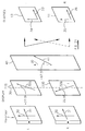
- FIG. 1 of the accompanying drawings illustrates this type of display, which comprises a spatial light modulator (SLM) 1 in the form of a liquid crystal device (LCD).
- SLM spatial light modulator
- the SLM 1 comprises front and rear transparent substrates 2 and 3 defining a cell containing a liquid crystal layer 4.
- the display also comprises a back light (not shown) for directing light through the SLM 1 towards a viewing region 5.
- the SLM 1 comprises a rectangular array of pixels, one of which is indicated diagrammatically at 6.
- the front substrate carries on its external surface a linear polariser 7 and an array of horizontal retarder stripes such as 8.
- the polariser 7 and the array of retarder stripes 8 form a micropolariser.
- light from the SLM 1 passing through the polariser 7 emerges with a first linear polarisation.
- the vertical width of the stripes 8 may be slightly less than the vertical pitch of the pixels 6 so as to ensure that an observer located in the viewing region 5 can see every row of pixels 6 of the SLM 1 through the correct retarder stripe 8 or a gap between adjacent retarder stripes. This is generally referred to as "viewpoint correction".
- Light passing from rows of pixels 6 aligned with gaps between the stripes 8 of the retarder propagates to the viewing region 5 with the linear polarisation determined by the polariser 7.
- Light from the rows of pixel 6 passing through the aligned stripes 8 of the retarder have their linear polarisation rotated through 90°.
- An observer indicated diagrammatically at 9 wears viewing spectacles with polarisers 10 and 11 which are oriented so that, for example, the polariser 10 passes light whose polarisation has been rotated by the retarder stripes 8 and attenuates light received directly from the polariser 7 whereas the polariser 11 passes light received directly from the polariser 7 but attenuates light received from the retarder stripes 8.
- the observer 9 perceives a stereoscopic three dimensional (3D) image.
- the observer 9 has considerable freedom of movement in a horizontal direction relative to the display and no undesirable visual artefacts will occur because of parallax between the stripes and the pixel apertures which are separated by the thickness of the substrate 2 and the polariser 7.
- the vertical freedom of movement is far more limited.
- the front substrate 2 is approximately 1.1 millimetres thick whereas the vertical pitch of the pixels 6 is typically about 300 micrometres.
- Correct performance of the display relies on the observer seeing the rows of pixels 6 through the respectively aligned retarder stripes 8 or gaps therebetween. Vertical movement of the observer 9 relative to the display out of the intended viewing region 5 immediately results in undesirable visual artefacts.
- Displays of the type shown in Figure 1 are of practical use only in applications where the limited vertical viewing freedom is not a problem, for example in desktop displays.
- Displays of this type are not suitable for reflective displays, where the display is generally tilted according to the prevailing lighting conditions so as to give the best display brightness, and for hand-held displays, such as dedicated games computers which are tilted during the playing process.
- This is illustrated in Figure 2 of the accompanying drawings, where an observer 9 tilts a display 1 in a direction indicated by a double-headed arrow 13 so as to obtain a best view of the display.
- a reflective display is typically illuminated by an overhead source 14 such as the sun, a lamp or a fluorescent tube.
- Such a bright small source tends to result in specular reflection as shown at 15 and the observer tilts the display so as to maximise display brightness while avoiding the specular reflection as shown at 15.
- the observer 9 may also obtain a best view on the other side of the specular reflection.
- Figure 3 of the accompanying drawings illustrates another known type of stereoscopic display, for example as disclosed in Japanese patent publication no. 9-304740.
- the display is of the transmissive type and is similar to that shown in Figure 1 except that a lenticular screen 12 whose cylindrically converging lenticules are oriented horizontally is disposed in front of the retarder array 8.
- a lenticular screen 12 whose cylindrically converging lenticules are oriented horizontally is disposed in front of the retarder array 8.
- the difference between the vertical pitch of the pixels 6 and the vertical pitch of the retarder stripes 8 is exaggerated to illustrate the viewpoint correction.
- the vertical pitch of the lenticules of the screen 12 is substantially equal to that of the retarder array 8 but, depending on the spacing between the lenticules 12 and the retarder stripes 8, is slightly less so as to match the viewpoint correction.
- the provision of the lenticular screen 12 substantially increases the vertical size of the viewing zone 5 and thus increases the vertical freedom of movement of an observer.
- the lenticular screen 12 must be manufactured to high tolerance for a high resolution display and must be accurately aligned with the retarder stripes 8 and the rows of pixels 6 in order to function correctly and avoid undesirable visual artefacts.
- the display shown in Figure 1 may be used to display 2D images at full resolution and with large viewing freedom merely by the observer 9 removing the viewing spectacles
- the display of Figure 3 when viewed without polarising glasses is less effective for 2D viewing.
- the lenticular screen 12 converts the spatially varying opaque addressing electrodes, pixel and black mask pattern of the SLM 1 to an angular pattern such that black regions between the horizontal rows of pixels 6 are converted into substantial intensity artefacts in the 2D viewing mode. This substantially limits the artefact free vertical freedom of movement of the observer in the 2D mode.
- Figure 4 of the accompanying drawings which illustrates black regions which are disposed between images of pixels and which represent images of black regions of the SLM 1 such as electrode lines covered by the black mask.
- JP 9-304740 also discloses an arrangement in which the retarder stripes and the lenticular screen are oriented vertically.
- the retarder stripe width is substantially equal to the pixel pitch.
- GB 2 321 815 relates to an autostereoscopic display with a viewer position indicator to assist a viewer in positioning himself within the orthoscopic viewing regions so as to avoid the pseudoscopic regions.
- the display makes use of a spatial light modulator and a parallax optic for generating the parallax for 3D viewing and also for making the positioning indication visible in the appropriate viewing regions.
- the parallax optic is a parallax barrier and details are given of a specific arrangement which makes use of a stripe-patterned retarder for varying the polarisation of light from the SLM with another polariser for analysing the output light to make the barrier structure visible.
- the retarder has relatively narrow slit regions and relatively wide barrier regions.
- US 5 317 393 discloses a stereoscopic display for use with crossed polarising glasses worn by an observer.
- An image display device has alternating columns for displaying left and right image strips with each pixel column lying behind a polariser. Adjacent polarisers have their polarising directions arranged orthogonally. The pitch of the individual polariser strips is equal to the pitch of the pixels.
- DE 3 203 339 discloses a stereoscopic display in which a vertically striped polariser is used in front of a television screen.
- a stereoscopic display comprising a spatial light modulator having an array of picture elements and a retarder array having horizontally alternating first and second vertically extending stripes, the first and second stripes being arranged to supply light from the modulator with first and second polarisations, respectively, which are different from each other, characterised in that each of the first and second stripes has a width which is greater than the horizontal pitch of the picture elements.
- each of the first and second stripes may be substantially equal to twice the horizontal pitch of the picture elements.
- the picture elements may be arranged as groups of four in horizontally and vertically adjacent pairs and the picture elements of each group may comprise red, green, green or white, and blue picture elements.
- each of the first and second stripes may be substantially equal to three times the horizontal pitch of the picture elements.
- the picture elements may be arranged as horizontally adjacent triplets of red, green and blue picture elements, each triplet being aligned with a respective first or second stripe.
- the green picture element may be disposed between the red and blue picture elements of each triplet.
- Each of the red and blue picture elements may be narrower than the green picture element of each triplet.
- the display may comprise a lenticular screen, each of whose lenticules is cylindrically converging and extends vertically, the horizontal pitch of the lenticules being substantially equal to the horizontal pitch of the picture elements.
- the lenticular screen may have a non-flat surface adjacent the modulator or the retarder.
- the modulator may be arranged to provide controllable attenuation of light.
- the modulator may comprise a liquid crystal device.
- the modulator may be of reflective type.
- the second polarisation may be substantially orthogonal to the first polarisation.
- the modulator is also possible for the modulator to be a light-emitting modulator, such as an electroluminescent or field emission display.
- the modulator may be arranged to supply linearly polarised light to the retarder array with the light being polarised parallel or perpendicular to a reference direction.
- the first stripes may be arranged to rotate polarisation by 90° and the second stripes may be arranged not to change polarisation.
- the first stripes may comprise half wave retarders.
- the half wave retarders may have optic axes oriented at substantially 45° to the reference direction.
- the first stripes may comprise first and second half wave retarders having optic axes oriented at substantially 22.5° and substantially 67.5°, respectively, to the reference direction.
- the first and second stripes may comprise half wave retarders whose optic axes are oriented at substantially +22.5° and substantially -22.5°, respectively, to the reference direction.
- the first and second stripes may comprise a further half wave retarder whose optic axis is oriented at substantially 67.5° to the reference direction.
- the first and second stripes may comprise half wave retarders whose optic axes are oriented at substantially +67.5° and substantially -67.5°, respectively, to the reference direction and a further half wave retarder whose optic axis is substantially parallel to the reference direction.
- the first and second stripes may comprise quarter wave retarders whose optic axes are oriented at substantially +45° and substantially -45°, respectively, to the reference direction and a further quarter wave retarder whose optic axis is oriented at substantially 45° to the reference direction.
- the display may comprise viewing spectacles having first and second linear polarisers with mutually orthogonal polarising directions.
- the first and second stripes may comprise quarter wave retarders whose optic axes are oriented at substantially +45° and substantially -45°, respectively, to the reference direction.
- the display may comprise viewing spectacles having first and second quarter wave retarders whose optic axes are oriented, in use, at substantially +45° and substantially -45°, respectively, to the reference direction and first and second linear polarisers with substantially parallel polarising directions.
- the first and second stripes may comprise half wave retarders whose optic axes are oriented at substantially +22.5° and substantially -22.5°, respectively, to the reference direction.
- the display may comprise viewing spectacles having first and second half wave retarders whose optic axes are oriented, in use, at substantially +67.5° and substantially -67.5°, respectively, to the reference direction and first and second linear polarisers with substantially parallel polarising directions.
- the first and second stripes may comprise a quarter wave retarder whose optic axis is oriented at substantially 90° to the reference direction.
- the spectacles may comprise a quarter wave retarder whose optic axis is oriented, in use, substantially parallel to the reference direction.
- the pitch of the retarder array compared to the pixel pitch is substantially longer than in the known displays and is therefore easier to fabricate, particularly as display resolution increases.
- Substantially increased vertical viewing freedom is provided so that such displays may be used, for example, as reflective displays which can be oriented to make best use of ambient lighting without suffering from undesirable visual artefacts.
- a display of this type maintains full spatial resolution when used in a 2D mode, for which it is merely necessary for an observer not to view the display through a stereoscopic viewing aid such as viewing spectacles.
- the horizontal viewing freedom is more limited, this is not a disadvantage in many applications and is more than offset by the increased vertical viewing freedom.
- the use of a lenticular screen allows the horizontal viewing freedom to be increased.
- each triplet represents a single composite colour pixel so that image data are supplied in turn horizontally for the composite colour pixels instead of interleaving the individual colour component pixels of adjacent left and right image data.
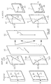
- a reflective display is illustrated in Figure 5a and comprises a spatial light modulator of the liquid crystal type comprising a rectangular array of red, green and blue pixels R, G, B, respectively.
- the pixels are arranged as horizontally adjacent triplets in each row, one such triplet being indicated at 20.
- a retarder array is disposed in front of the SLM and comprises vertical stripes.
- the retarder array comprises first stripes such as 21 and 22 which alternate horizontally with second stripes (illustrated as being clear in Figure 5a).
- the width of each of the stripes is substantially equal to three times the horizontal pitch of the pixels R, G, B so that each stripe is disposed in front of and aligned with a respective column of triplets of individual pixels forming a column of composite colour pixels.
- the widths of the retarder stripes may be slightly less than three times the pitch of the individual pixels so as to provide view point correction as described hereinbefore.
- the display illustrated in Figure 5a has a further advantage over displays of the type illustrated in Figure 1 (when the retarder stripes are vertical).
- the left and right colour component pixel information would need to be interleaved on a pixel by pixel basis as illustrated in Figure 5b.
- the left and right view information is interleaved on a composite colour pixel basis.
- the three colour components for one of the views are supplied to three adjacent individual colour pixels. This allows the supply of left and right image data to the display to be simplified.
- Figure 6 illustrates the creation of several lobes which repeat the viewing windows with lateral spacing at the viewing plane.
- the zero order lobe corresponds to imaging of the pixels directly below the lenticular elements of the lenticular screen 12.
- each such lenticule images adjacent composite pixels into different order lobes, each of which permits orthoscopic viewing over three lobes (as shown in Figure 7).
- Figure 7 illustrates the effects of crosstalk in the display of Figure 5a.
- the intensity of each colour across the lobes in the window plane is illustrated diagrammatically in the upper part of Figure 7.
- the dips in intensity at the edges of each lobe correspond to imaging of opaque regions between the columns of pixels.
- the + 1, 0 and -1 lobes of the green pixels contain green light of the same polarisation, for example corresponding to the left image.
- the 0, 1 and 2 lobes contain red data of the same polarisation and the -2, -1 and 0 lobes contain blue data of the same polarisation.
- the lower part of Figure 7 indicates pseudoscopic zones with a high value and orthoscopic zones with a low value so as to illustrate the viewing windows generated by the display of Figure 5a.
- the orthoscopic zone is surrounded by a wide zone which is free from crosstalk in the green part of the image, which is generally the high luminance component.
- each orthoscopic zone is surrounded by a fully pseudoscopic zone.
- the arrangement illustrated in Figure 5a provides better freedom from pseudoscopic viewing.
- red or blue pixel could be disposed at the centre of each composite pixel.
- the display shown in Figure 8 differs from that shown in Figure 5a in that the red and blue pixels R, B are narrower than the green pixels G. such an arrangement reduces the crosstalk for horizontal movement of an observer outside the viewing zone as compared with the display shown in Figure 5a. Although this is achieved at the expense of a dimming artefact, the performance of the display of Figure 8 may be more suitable for certain applications than that of the display of Figure 5a.
- each of the retarder stripes is (apart from variations for viewpoint correction) substantially equal to twice the horizontal pitch of the individual pixels.
- each composite colour pixel 20 comprises four individual colour component pixels in the form of a red pixel R a blue pixel B and two green pixels G. Alternatively, one of the green pixels may be replaced by a white pixel.
- each composite pixel comprises vertically and horizontally adjacent pairs.
- Figure 9 illustrates a particular layout in which the green pixels G are disposed in the same vertical column with the red and blue pixels being disposed in an adjacent column.
- Such an arrangement provides the substantially increased vertical viewing freedom as with the displays shown in Figure 5a and 8 Although the horizontal crosstalk is reduced, the reduction is not as large as for the displays shown in Figures 5a and 8.
- the display shown in Figure 10 differs from that shown in Figure 9 in that the green pixels G of each composite pixel 20 are disposed diagonally with respect to each other.
- the display shown in Figure 11 differs from that shown in Figure 9 in the individual pixel layout within each composite pixel 20.
- the green pixels G of each composite pixel 20 are disposed in the same row adjacent each other.
- Such an arrangement allows a simpler colour filter pattern to be used although more crosstalk occurs between green pixels than for the display shown in Figures 9 and 10.
- Figure 12 illustrates a display which differs from that shown in Figure 9 only in that one of the green pixels G of each composite pixel 20 is replaced by a white or luminance pixel Y. Similarly, one of the green pixels of each composite pixel of the displays shown in Figures 10 and 11 may be replaced by a white pixel. In the arrangement shown in Figure 12, crosstalk occurs between the white and blue pixels and between the green and red pixels of adjacent composite pixels. Such an arrangement may be preferable to crosstalk between green and white pixels.
- Figure 13 illustrates a display which differs from that shown in Figure 5a in that it is provided with a lenticular screen 12.
- the lenticules of the screen 12 are cylindrically converging and extend vertically.
- the horizontal pitch of the lenticules is, subject to the needs of viewpoint correction, substantially equal to the horizontal pitch of the pixels RGB.
- each of the lenticules is substantially aligned with a respective column of pixels. This arrangement provides substantially increased horizontal viewing freedom while maintaining the increased vertical viewing freedom.
- the lenticular screen 12 may also be used with the displays illustrated in Figures 8 to 12 to provide increased horizontal viewing freedom.
- the pixel behind each lenticule is imaged by the lenticular sheet to a window.
- a point source such as the sun
- the light source will be imaged to part of the window as illustrated at "a" in Figure 18.
- the window will not be uniformly illuminated, and it is therefore preferable to illuminate the display with an extended source.
- the pixel reflector incorporates a coarse diffusing element which can be resolved by the lenticular sheet (as typically used in commercial reflective displays), then a point source illumination is still imaged substantially to a point. However the intensity of light at that point is determined by the amount and direction of scatter from the surface.
- Some light for instance can be scattered into an adjacent lenticule and travel to an adjacent lobe.
- the point on the reflector surface at which reflection takes place varies and, if the scattering element is coarse, then the amount of light reaching the observer eyes also varies. There will therefore also be different and varying light levels in each eye as the observer moves.
- the scattering element contains the same pattern within each pixel so that the scattering effect is correlated across the panel, then this effect is quite noticeable. It is therefore preferable to employ scattering elements which are not correlated pixel to pixel, at least in the horizontal direction.
- a scattering reflector which is not resolved by the lenticular sheet may be used, in which case the scattering element at each pixel may be correlated or non-correlated with the other pixels.
- the display shown in Figure 14 illustrates how the lenticular screen 12 may be used with a display of the type shown in Figure 8.
- FIG 15 illustrates the construction of a stereoscopic display in more detail.
- the display comprises a spatial light modulator (SLM) 1 in the form of a liquid crystal device with front and rear substrates 2 and 3 defining therebetween a cell containing a liquid crystal 4.
- the pixels 6 are arranged as R, G, B triplets as illustrated in Figure 5a.
- the colour for the pixels may be provided by filters disposed on the substrate 2.
- the retarder array comprises the first stripes 21 and 22 and the second stripes 23 (only part of the display is shown in Figure 15 for the sake of clarity).
- the SLM 1 has an output linear polariser 7 which supplies linearly polarised light to the retarder array.
- the first stripes 21 and 22 supply light from the SLM 1 to the observer 9 with a first polarisation whereas the second stripes 23 supply light with a second polarisation which is different from and preferably orthogonal to the first polarisation.
- the observer 9 wears viewing spectacles comprising polarisers 10 and 11.
- the requirements of the polarisers 10 and 11 are that they should transmit light, for example, from the first stripes and the second stripes, respectively, with minimum attenuation and as achromatically as possible whereas they should block light from the second and first stripes, respectively, as much and as achromatically as possible.
- the first stripes 21 and 22 are aligned with pixels which display left eye view information whereas the second stripes 23 are aligned with pixels which display right eye view information.
- the 3D image can be viewed stereoscopically with minimum crosstalk and other visual artefacts.
- the viewing region 5 extends vertically so that the observer 9 has considerable vertical viewing freedom.
- the horizontal freedom is more restricted but the effects of crosstalk on visual disturbance may be reduced as described hereinbefore.
- the SLM 1 may include an input polariser (not shown) on the substrate 3.
- the display shown in Figure 16 differs from that shown in Figure 15 in that the lenticular screen 12 is shown facing the other way such that its curved side is adjacent the retarder array comprising the stripes 21 to 23. Such an arrangement prevents the curved side from being clogged with contaminants so as to preserve the performance of the display. Also, where the lenticular screen 12 is formed on a substrate 12a of substantial thickness, the arrangement shown in Figure 16 has reduced parallax as compared with an arrangement of the type shown in Figure 15. This arrangement may have worse aberrational performance than that shown in Figure 15 because the most curved surface is on the short conjugate side. It is difficult to provide an effective anti-reflection coating for the curved surface of a lenticular sheet.
- the display shown in Figure 17 differs from that of Figure 16 in that the polariser 7 is disposed internally of the liquid crystal device.
- Such an arrangement reduces the parallax between the pixels and the retarder array, particularly if the approximately 100 micron thick tri-cellulose acetate protection layers on either side of typical commercial polarisers are eliminated when the polariser is disposed internally.
- the reduced parallax allows an improvement in the minimum viewing distance.
- Figure 19 illustrates an arrangement of the optical components of the display and of spectacles or glasses worn by the observer.
- the polariser 7 is uniform and has a polarisation axis 31 orthogonal to a reference direction so that light from the left image pixels L and the right image pixels R is transmitted with a (vertical) polarisation direction illustrated at 30 and corresponding to the reference direction.
- the polarisation axis 31 and the polarisation direction 30 may be rotated by 90° without affecting the operation of the display.
- the first stripes 21 of the retarder array comprise half wave plates with an optic axis 32 oriented at 45° (in either direction) with respect to the reference direction 30.
- the vertically polarised light from the polariser 7 for the left image pixels is thus rotated so that the light supplied to the glasses by the first stripes 21 is horizontally polarised.
- the second stripes 23 are arranged to have no effect on the polarisation of light from the polariser 7, which thus remains vertically polarised.
- the second stripes 23 may be arranged to provide zero retardation.
- the second stripes may comprise half wave plates whose optic axis is parallel or perpendicular to the reference direction 30.
- the polariser 10 for the left eye of the observer has a polarisation axis 34 which is substantially parallel to the reference direction 30 when the glasses are worn by an observer whose head is not tilted with respect to the display.
- the polariser 10 passes light of horizontal polarisation as indicated at 33 but attenuates light of vertical polarisation.
- the polariser 11 for the right eye of the observer has a polarisation axis 36 which is perpendicular to the reference direction 30 and so passes vertically polarised light as indicated at 35.
- the polariser 10 receives vertically polarised light from the left pixels L and transmits this to the left eye. However, the chromatic performance is determined by the chromatic performance of the half wave plate 21.
- the polarisation axis of the polariser 10 is perpendicular to the polarisation axis of the polariser 7 and the second stripes 23 have substantially no effect on the polarisation of light from the right pixels R. Thus, extinction of light from the right pixels is good.
- the polariser 11 has its polarisation axis 36 parallel to the polarisation axis 31 of the polariser 7 so that the transmission of light from the right pixels R is good.
- the chromatic performance is very good.
- the extinction of light by the polariser 11 from the left pixels relies on the performance of the half wave plate first stripes 21, the chromatic performance is determined by the half wave plate. Accordingly, the performance of the optics for the left and right eyes of the observer is not equivalent with the arrangement shown in Figure 19.
- the arrangement shown in Figure 20 differs from that shown in Figure 19 in that the retarder array comprises a two stage retarder configuration to improve the chromatic performance.
- the first stripes comprise a first half waveplate 21a whose optic axis is oriented at 22.5° with respect to the reference direction 30 and a second half waveplate 21b whose optic axis is oriented at 67.5° in the same sense relative to the reference direction 30.
- the second stripes comprise two layers 23a and 23b which have no effect on polarisation. This arrangement improves the chromatic performance for the light transmitted by the polariser 10 and the light extinguished by the polariser 11.
- the chromatic performance is still dependent on the chromatic performance of the half wave plates 21a and 21b in combination so that the performance for the optics for the left and right eyes is not equivalent.
- two patterned layers have to be aligned with each other to provide the retarder array.
- the arrangement shown in Figure 21 differs from that shown in Figure 20 in that the second stripes comprise a first layer 23a in the form of a half waveplate with its optic axis oriented at -22.5° with respect to the reference direction 30.
- the second layer comprises a uniform half wave retarder 40 whose optic axis is oriented at +67.5° to the reference direction 30.
- the left eye sees transmission via a two stage retarder and crossed retarder extinction.
- the right eye sees crossed retarder transmission but two stage retarder extinction.
- the left eye sees good achromatic transmission but extinction limited by retarder performance whereas the right eye sees good transmission but limited extinction.
- the performance of the optics for each eye is not equivalent.
- Figure 22 illustrates an arrangement in which the performance of the optics for each eye is equivalent.
- the arrangement of Figure 22 differs from that of Figure 21 in that the optic axes 32a and 32b of the half wave plates 21a and 23a are oriented at +67.5° and - 67.5°, respectively, the optic axis 41 of the half wave plate 40 is substantially parallel to the reference direction 30 and the polarising axes 34 and 36 of the polarisers 10 and 11 are rotated by 45° in the negative (anti-clockwise) direction so as to be disposed at -45° and +45°, respectively, relative to the reference direction 30.
- transmitted light performance is determined by a two stage achromatic retarder configuration and is therefore good. However, extinction is limited by the retarder performance.
- the arrangement shown in Figure 23 uses the same polarisers 10 and 11 as shown, for example, in Figure 20.
- the retarder array comprises two layers, each of which is a quarter wave retarder.
- the quarter wave retarder 21a for the left image pixels has an optic axis 32a oriented at +45° relative to the reference direction 30 whereas the quarter wave retarder 23a for the second stripes has an optic axis 32b oriented at -45° to the reference direction 30.
- Both stripes comprise a quarter wave retarder 40 whose optic axis 41 is oriented at +45° to the reference direction 30.
- the left eye of the observer sees good extinction of the light from the right image pixels because this is equivalent to crossed retarders. However, the transmitted light from the left image pixels relies on the chromatic performance of two retarders. Conversely, the right eye sees limited extinction of the light from the left image pixels because this relies on the chromatic performance of two retarders. However, transmission of light from the right image pixels is good.
- the arrangement shown in Figure 24 differs from that shown in Figure 23 in that the quarter wave plate 40 is omitted from the display but quarter wave plates 40a and 40b are provided in the viewing glasses.
- the optic axis 41a of the quarter wave plate 40a is oriented at +45° to the reference direction 30 whereas the optic axis 41b of the quarter wave plate 40b is oriented at -45° to the reference direction 30.
- the quarter wave plate 40a is provided for the left eye of the observer with the polarisation direction of the polariser 10 being at 33.
- the quarter wave plate 40b is provided for the right eye of the observer with the polarisation direction of the polariser 11 being at 36.
- each eye sees the extinction from crossed retarders but chromatic transmission from two retarders.
- light propagating from the display to the glasses is circularly polarised so that tilting of the head of the observer does not substantially affect the perceived 3D image.
- the arrangement shown in Figure 25 differs from that shown in Figure 21 in that the half wave retarder 40 is omitted but half wave retarders 42 and 44 are provided in the glasses for the left and right eyes, respectively, of the observer.
- the optic axis 43 of the half wave plate 42 is oriented at +67.5° relative to the reference direction 30 whereas the optic axis 45 of the retarder 44 is oriented at -67.5° to the reference direction 30.
- This configuration of retarders provides improved chromatic performance for transmission of light to each eye while retaining good achromatic extinction of light not intended for that eye.
- the arrangement shown in Figure 26 differs from that shown in Figure 25 in that the display comprises a quarter wave plate 50 whose optic axis 51 is substantially perpendicular to the reference direction 30 and the glasses comprise a quarter wave plate 52 whose optic axis 53 is substantially parallel to the reference direction 30.
- This arrangement therefore achieves the advantages of the arrangement of Figure 25 with some possible degradation in the chromatic performance because of the presence of the quarter wave plates 50 and 52.
- this arrangement has the advantage of the arrangement shown in Figure 24 in that light propagating from the display to the glasses is circularly polarised so as to allow tilting of the head of the observer without substantial degradation of the optical performance.
- any of the embodiments of the invention may be used in a stereoscopic display in which an indication of the correct i.e. orthoscopic viewing condition is provided by a further optical element, for example as disclosed in EP 0 860 728 and GB 2 321 815.
- Figure 27 shows another type of display which makes use of a reflective spatial light modulator 1 of liquid crystal type and a retarder array comprising stripes 21 to 23.
- the observer 9 wears glasses comprising substantially identical polarisers 10 and 11 with their polarising axes oriented parallel to each other.
- the light reflected by the SLM 1 is linearly polarised and the polarisation direction is unaffected by passage through the stripes 23.
- the polarisation of the reflected light is changed or rotated by 90° by the stripes 21 and 22.
- the polarisers 10 and 11 are orientated such that they pass light from only one of the sets of stripes.
- the combination of the retarders and the polarisers thus forms a parallax barrier and allows 3D viewing of the display.
- the observer 9 removes the polarising glasses so that the barrier structure is no longer visible.
- 2D images may be viewed at the full resolution and full brightness of the display.
- Figure 28 illustrates an alternative mode of use of the display of Figure 27.
- the observer 9 views the display through a sheet polariser 60 to allow the barrier structure to be visible for 3D viewing.
- the polariser 60 may be moved or removed so as to allow the observer 9 to see the display unimpeded for 2D viewing.
- the display is illuminated by ambient light or light from a light source shown at 61 in Figure 28.
- the light source may comprise light emitting diode, ambient light or a combination of light sources.
- the display is illuminated in both modes of operation by a substantial amount of light which has not passed through a polariser before being reflected by the display. An increased amount of light is thus available for reflection by the display, which can therefore provide a brighter image than reflective displays incorporating a "3D" polariser directly above the retarder array 21-23.
- retarder arrangement illustrated in Figures 27 and 28 may be replaced by polarisation modifying layers of the type disclosed in EP 0 829 744 and GB 2 317 295, the contents of both of which are incorporated herein by reference.
Abstract
Description
The arrangement shown in Figure 23 uses the same polarisers 10 and 11 as shown, for example, in Figure 20. The retarder array comprises two layers, each of which is a quarter wave retarder. The quarter wave retarder 21a for the left image pixels has an optic axis 32a oriented at +45° relative to the
Claims (29)
- A stereoscopic display comprising a spatial light modulator (1) having an array of picture elements (6) and a retarder array having horizontally alternating first and second vertically extending stripes (21-23), the first and second stripes (21-23) being arranged to supply light from the modulator (1) with first and second polarisations, respectively, which are different from each other, characterised in that each of the first and second stripes (21-23) has a width which is greater than the horizontal pitch of the picture elements (6).
- A display as claimed in claim 1, characterised in that the width of each of the first and second stripes (21-23) is substantially equal to twice the horizontal pitch of the picture elements (6).
- A display as claimed in claim 2, characterised in that the picture elements (6) are arranged as groups of four in horizontally and vertically adjacent pairs and the picture elements (6) of each group comprise red (R), green (G), green (G) or white (Y) and blue (B) picture elements.
- A display as claimed in claim 1, characterised in that the width of each of the first and second stripes (21-23) is substantially equal to three times the horizontal pitch of the picture elements (6).
- A display as claimed in claim 4, characterised in that the picture elements (6) are arranged as horizontally adjacent triplets (20) of red (R), green (G) and blue (B) picture elements, each triplet (20) being aligned with a respective first or second stripe (21-23).
- A display as claimed in claim 5, characterised in that the green picture element (G) is disposed between the red and blue picture elements (R, B) of each triplet (20).
- A display as claimed in claim 5 or 6, characterised in that each of the red and blue picture elements (R, B) is narrower than the green picture element (G) of each triplet (20).
- A display as claimed in any one of the preceding claims, characterised by a lenticular screen (12), each of whose lenticules is cylindrically converging and extends vertically, the horizontal pitch of the lenticules being substantially equal to the horizontal pitch of the picture elements (6).
- A display as claimed in claim 8, characterised in that the lenticular screen (12) has a non-flat surface adjacent the modulator (1) or the retarder array.
- A display as claimed in any one of the preceding claims, characterised in that the modulator (1) is arranged to provide controllable attenuation of light.
- A display as claimed in claim 10, characterised in that the modulator (1) comprises a liquid crystal device.
- A display as claimed in any one of the proceeding claims, characterised in that the modulator (1) is of reflective type.
- A display as claimed in any one of the preceding claims, characterised in that the second polarisation is substantially orthogonal to the first polarisation.
- A display as claimed in any one of the preceding claims, characterised in that the modulator (1) is arranged to supply linearly polarised light to the retarder array with the light being polarised parallel or perpendicular to a reference direction (30).
- A display as claimed in claim 14, characterised in that the first stripes (21,22) are arranged to rotate polarisation by 90° and the second stripes (23) are arranged not to change polarisation.
- A display as claimed in claim 15, characterised in that the first stripes (21, 22) comprise half wave retarders.
- A display as claimed in claim 16, characterised in that the half wave retarders (21, 22) have optic axes (32) oriented at substantially 45° to the reference direction (30).
- A display as claimed in claim 15, characterised in that the first stripes (21, 22) comprise first and second half wave retarders (21a, 21b) having optic axes oriented at substantially 22.5° and substantially 67.5°, respectively, to the reference direction (30).
- A display as claimed in claim 14, characterised in that the first and second stripes (21-23) comprise half wave retarders (21a, 23a) whose optic axes are oriented at substantially +22.5° and substantially -22.5°, respectively, to the reference direction (30).
- A display as claimed in claim 19, characterised in that the first and second stripes (21-23) comprise a further half wave retarder (40) whose optic axis (41) is oriented at substantially 67.5° to the reference direction (30).
- A display as claimed in claim 14, characterised in that the first and second stripes (21-23) comprise half wave retarders (21a, 23a) whose optic axes (32a, 32b) are oriented at substantially +67.5° and substantially -67.5°, respectively, to the reference direction (30) and a further half wave retarder (40) whose optic axis (41) is substantially parallel to the reference direction.
- A display as claimed in claim 14, characterised in that the first and second stripes (21-23) comprise quarter wave retarders (21a, 23a) whose optic axes (32a, 32b) are oriented at substantially +45° and substantially -45°, respectively, to the reference direction (30) and a further quarter wave retarder (40) whose optic axis (41) is oriented at substantially +45° to the reference direction (30).
- A display as claimed in any one of claims 15 to 22, characterised by viewing spectacles having first and second linear polarisers (10, 11) with mutually orthogonal polarising directions (34, 36).
- A display as claimed in claim 14, characterised in that the first and second stripes (21-23) comprise quarter wave retarders (21a, 23a) whose optic axes (32a, 32b) are oriented at substantially +45° and substantially -45, respectively, to the reference direction (30).
- A display as claimed in claim 24, characterised by viewing spectacles having first and second quarter wave retarders (40a, 40b) whose optic axes (41a, 41b) are oriented, in use, at substantially +45° and -45°, respectively, to the reference direction (30) and first and second linear polarisers (10, 11) with substantially parallel polarising directions (34, 35).
- A display as claimed in claim 14, characterised in that the first and second stripes (21-23) comprise half wave retarders (21a, 23a) whose optic axes (32a, 32b) are oriented at substantially +22.5° and substantially -22.5°, respectively, to the reference direction (30).
- A display as claimed in claim 26, characterised by viewing spectacles having first and second half wave retarders (42, 44) whose optic axes (43, 45) are oriented, in use, at substantially +67.5° and substantially -67.5°, respectively, to the reference direction (30) and first and second linear polarisers (10, 11) with substantially parallel polarising directions (34, 35).
- A display as claimed in claim 26 or 27, characterised in that the first and second stripes (21-23) comprise a quarter wave retarder (50) whose optic axis (51) is oriented at substantially 90° to the reference direction (30).
- A display as claimed in claim 28 when dependent on claim 27, characterised in that the spectacles comprise a quarter wave retarder (52) whose optic axis (53) is oriented, in use, substantially parallel to the reference direction (30).
Applications Claiming Priority (2)
| Application Number | Priority Date | Filing Date | Title |
|---|---|---|---|
| GB9915781 | 1999-07-07 | ||
| GB9915781A GB2351866A (en) | 1999-07-07 | 1999-07-07 | Stereoscopic display |
Publications (2)
| Publication Number | Publication Date |
|---|---|
| EP1067805A2 true EP1067805A2 (en) | 2001-01-10 |
| EP1067805A3 EP1067805A3 (en) | 2003-01-15 |
Family
ID=10856723
Family Applications (1)
| Application Number | Title | Priority Date | Filing Date |
|---|---|---|---|
| EP00305693A Withdrawn EP1067805A3 (en) | 1999-07-07 | 2000-07-06 | Stereoscopic display |
Country Status (4)
| Country | Link |
|---|---|
| US (1) | US6703989B1 (en) |
| EP (1) | EP1067805A3 (en) |
| JP (1) | JP2001075049A (en) |
| GB (1) | GB2351866A (en) |
Cited By (21)
| Publication number | Priority date | Publication date | Assignee | Title |
|---|---|---|---|---|
| EP1401216A3 (en) * | 2002-09-17 | 2006-02-08 | Sharp Kabushiki Kaisha | Autostereoscopic display |
| WO2006033447A2 (en) * | 2004-09-21 | 2006-03-30 | Sharp Kabushiki Kaisha | Multiple view display |
| WO2006038819A1 (en) * | 2004-10-01 | 2006-04-13 | Pure Depth Limited | Improved stereoscopic display |
| EP1708515A1 (en) * | 2005-03-30 | 2006-10-04 | Sanyo Epson Imaging Devices Corporation | Liquid crystal display device with which a plurality of observers can visually recognize each of two different images displayed on a single LCD panel |
| US7646537B2 (en) | 2006-01-03 | 2010-01-12 | Samsung Electronics Co., Ltd, | High-resolution field sequential autostereoscopic display |
| US7653371B2 (en) | 2004-09-27 | 2010-01-26 | Qualcomm Mems Technologies, Inc. | Selectable capacitance circuit |
| US7808703B2 (en) | 2004-09-27 | 2010-10-05 | Qualcomm Mems Technologies, Inc. | System and method for implementation of interferometric modulator displays |
| US7903047B2 (en) | 2006-04-17 | 2011-03-08 | Qualcomm Mems Technologies, Inc. | Mode indicator for interferometric modulator displays |
| US7920135B2 (en) | 2004-09-27 | 2011-04-05 | Qualcomm Mems Technologies, Inc. | Method and system for driving a bi-stable display |
| EP2376973A1 (en) * | 2009-01-09 | 2011-10-19 | Eastman Kodak Company | Dual-view stereoscopic display using linear modulator arrays |
| US8059326B2 (en) | 1994-05-05 | 2011-11-15 | Qualcomm Mems Technologies Inc. | Display devices comprising of interferometric modulator and sensor |
| US20120162763A1 (en) * | 2010-12-28 | 2012-06-28 | Lg Display Co., Ltd. | Image display device |
| CN102778756A (en) * | 2011-05-12 | 2012-11-14 | 乐金显示有限公司 | Image display device |
| WO2013185393A1 (en) * | 2012-06-13 | 2013-12-19 | 深圳市华星光电技术有限公司 | Three-dimensional image display device |
| US8885244B2 (en) | 2004-09-27 | 2014-11-11 | Qualcomm Mems Technologies, Inc. | Display device |
| US8928967B2 (en) | 1998-04-08 | 2015-01-06 | Qualcomm Mems Technologies, Inc. | Method and device for modulating light |
| TWI471605B (en) * | 2010-12-28 | 2015-02-01 | Lg Display Co Ltd | Image display device |
| US8971675B2 (en) | 2006-01-13 | 2015-03-03 | Qualcomm Mems Technologies, Inc. | Interconnect structure for MEMS device |
| EP2584555A4 (en) * | 2011-07-13 | 2015-03-11 | Boe Technology Group Co Ltd | Display panel and display device |
| US9110289B2 (en) | 1998-04-08 | 2015-08-18 | Qualcomm Mems Technologies, Inc. | Device for modulating light with multiple electrodes |
| EP2607942A4 (en) * | 2010-08-20 | 2017-05-31 | LG Chem, Ltd. | Multi-functional optical filter for stereoscopic image display and stereoscopic image display device including same |
Families Citing this family (50)
| Publication number | Priority date | Publication date | Assignee | Title |
|---|---|---|---|---|
| JP4517493B2 (en) * | 2000-10-18 | 2010-08-04 | ソニー株式会社 | Solid-state imaging device and signal processing method thereof |
| JP2003029207A (en) * | 2001-07-11 | 2003-01-29 | Sony Corp | 3d video display body |
| JP4403688B2 (en) * | 2002-10-11 | 2010-01-27 | ソニー株式会社 | Polarizing means and position holding mechanism thereof |
| JP4398141B2 (en) * | 2002-10-31 | 2010-01-13 | パイオニア株式会社 | Display apparatus and method |
| US7425951B2 (en) * | 2002-12-27 | 2008-09-16 | Kabushiki Kaisha Toshiba | Three-dimensional image display apparatus, method of distributing elemental images to the display apparatus, and method of displaying three-dimensional image on the display apparatus |
| US7301587B2 (en) | 2003-02-28 | 2007-11-27 | Nec Corporation | Image display device and portable terminal device using the same |
| JP4698616B2 (en) * | 2003-02-28 | 2011-06-08 | Nec液晶テクノロジー株式会社 | Image display device and portable terminal device using the same |
| EP1668920A1 (en) * | 2003-09-20 | 2006-06-14 | Koninklijke Philips Electronics N.V. | Improving image quality in an image display device |
| EP1668922B1 (en) * | 2003-09-20 | 2014-03-26 | Koninklijke Philips N.V. | Image display device |
| US7372629B2 (en) | 2003-11-06 | 2008-05-13 | Nec Corporation | Three-dimensional image display device, portable terminal device, display panel and fly eye lens |
| US7221332B2 (en) * | 2003-12-19 | 2007-05-22 | Eastman Kodak Company | 3D stereo OLED display |
| JP3944188B2 (en) * | 2004-05-21 | 2007-07-11 | 株式会社東芝 | Stereo image display method, stereo image imaging method, and stereo image display apparatus |
| KR101112548B1 (en) * | 2004-12-10 | 2012-02-15 | 삼성전자주식회사 | Micro lens substrate for 3d display, 3d display apparatus and manufacturing method thereof |
| KR100922348B1 (en) | 2005-08-29 | 2009-10-21 | 삼성모바일디스플레이주식회사 | Three-dimensional display device |
| WO2007111012A1 (en) * | 2006-03-27 | 2007-10-04 | Sharp Kabushiki Kaisha | Liquid crystal display device |
| US20090102767A1 (en) * | 2006-03-27 | 2009-04-23 | Makoto Shiomi | Liquid Crystal Display Apparatus |
| US8077195B2 (en) * | 2006-07-24 | 2011-12-13 | Seefront Gmbh | Autostereoscopic system |
| KR101255275B1 (en) | 2006-10-13 | 2013-04-15 | 엘지디스플레이 주식회사 | Steroscopic Liquid Crystal Display Device, method for Manufacturing the same and Bonding Apparatus for the same |
| DE602007007238D1 (en) * | 2006-12-19 | 2010-07-29 | Koninkl Philips Electronics Nv | AUTOSTEREOSCOPIC DISPLAY DEVICE AND SYSTEM THEREWITH |
| US8289228B2 (en) * | 2007-04-18 | 2012-10-16 | Seiko Epson Corporation | Display device, method of driving display device, and electronic apparatus |
| JP2009258582A (en) | 2007-09-05 | 2009-11-05 | Toshiba Corp | Three-dimensional image display device, method and device for manufacturing three-dimensional image display device, and apparatus for manufacturing the three-dimensional image display device |
| TWI381191B (en) * | 2007-12-03 | 2013-01-01 | Au Optronics Corp | Three-dimensional display device and fabricating method thereof |
| JP5176204B2 (en) * | 2008-04-07 | 2013-04-03 | Nltテクノロジー株式会社 | Liquid crystal panel and manufacturing method thereof |
| EP2519014B1 (en) * | 2008-04-22 | 2014-05-14 | Ehn Spire Limited Liability Company | Position-permissive autostereoscopic display systems and methods |
| GB2461907A (en) * | 2008-07-17 | 2010-01-20 | Sharp Kk | Angularly restricted display |
| US8350940B2 (en) * | 2009-06-08 | 2013-01-08 | Aptina Imaging Corporation | Image sensors and color filter arrays for charge summing and interlaced readout modes |
| JP5667752B2 (en) * | 2009-08-20 | 2015-02-12 | 株式会社ジャパンディスプレイ | 3D image display device |
| KR20110024970A (en) * | 2009-09-03 | 2011-03-09 | 삼성전자주식회사 | Stereo-scopic image display device |
| US20110063725A1 (en) * | 2009-09-17 | 2011-03-17 | Eyesaver International | Lenticular Display |
| JP2011150274A (en) * | 2009-12-25 | 2011-08-04 | Fujifilm Corp | Video display system |
| US20120038853A1 (en) * | 2010-08-12 | 2012-02-16 | Chimei Innolux Corporation | Display device, display apparatus for displaying 3d image and method for changing polarization direction of light emitted from liquid crystal display device |
| CN103154801B (en) * | 2010-10-13 | 2015-02-11 | 夏普株式会社 | Display device |
| US9105224B2 (en) | 2010-11-24 | 2015-08-11 | Sharp Kabushiki Kaisha | Stereoscopic display device |
| KR101709160B1 (en) * | 2010-12-20 | 2017-02-22 | 엘지디스플레이 주식회사 | Device for displaying 2D/3D display-convertible image |
| KR101781507B1 (en) * | 2010-12-20 | 2017-09-25 | 엘지디스플레이 주식회사 | Device for displaying 2D/3D display-convertible image |
| WO2013008334A1 (en) * | 2011-07-14 | 2013-01-17 | Necディスプレイソリューションズ株式会社 | Liquid-crystal display device and display control method |
| KR101578695B1 (en) * | 2011-12-02 | 2015-12-22 | 엘지디스플레이 주식회사 | Glass patterned retarder stereoscopic 3d display device and method of fabricating the same |
| JP5779124B2 (en) * | 2012-03-13 | 2015-09-16 | 株式会社ジャパンディスプレイ | Display device and electronic device |
| KR20130106217A (en) * | 2012-03-19 | 2013-09-27 | 삼성디스플레이 주식회사 | Method of displaying three-dimensional stereoscopic image and an display apparatus for performing the same |
| WO2013179190A1 (en) * | 2012-06-01 | 2013-12-05 | Koninklijke Philips N.V. | Autostereoscopic display device and driving method |
| US8958043B2 (en) * | 2012-07-05 | 2015-02-17 | Shenzhen China Star Optoelectronics Technology Co., Ltd. | 3D liquid crystal display device and pixel structure thereof |
| CN102866528B (en) * | 2012-09-07 | 2016-03-16 | 深圳超多维光电子有限公司 | Display device |
| KR20140096661A (en) * | 2013-01-28 | 2014-08-06 | 삼성전자주식회사 | Glasses-free reflective 3D color display |
| JP2015118191A (en) * | 2013-12-17 | 2015-06-25 | 富士通株式会社 | Information display system, information display device, and spectacles |
| EP3375186B1 (en) * | 2015-11-10 | 2019-08-28 | Koninklijke Philips N.V. | Display device and display control method |
| GB201608900D0 (en) * | 2016-05-20 | 2016-07-06 | Barco Nv | Selective projection display screen |
| KR102522397B1 (en) * | 2016-11-29 | 2023-04-17 | 엘지디스플레이 주식회사 | Autostereoscopic image display device |
| US10969740B2 (en) | 2017-06-27 | 2021-04-06 | Nvidia Corporation | System and method for near-eye light field rendering for wide field of view interactive three-dimensional computer graphics |
| WO2020044969A1 (en) * | 2018-08-28 | 2020-03-05 | 株式会社Jvcケンウッド | Stereoscopic image display monitor and stereoscopic image display device |
| JP7156092B2 (en) * | 2018-08-28 | 2022-10-19 | 株式会社Jvcケンウッド | 3D image display monitor and 3D image display device |
Citations (4)
| Publication number | Priority date | Publication date | Assignee | Title |
|---|---|---|---|---|
| JPH09304740A (en) * | 1996-03-15 | 1997-11-28 | Sharp Corp | Picture display device |
| JPH10253824A (en) * | 1997-03-13 | 1998-09-25 | Sharp Corp | Optical element and manufacture therefor and image display device using the same |
| JPH10268233A (en) * | 1997-01-22 | 1998-10-09 | Sharp Corp | Image display device |
| US5956001A (en) * | 1996-03-15 | 1999-09-21 | Sharp Kabushiki Kaisha | Image display device |
Family Cites Families (8)
| Publication number | Priority date | Publication date | Assignee | Title |
|---|---|---|---|---|
| DE3203339A1 (en) | 1982-02-02 | 1983-09-08 | Montanus, Ernst Günter, 8399 Ruhstorf | Device for the three-dimensional reproduction of television images |
| KR940008046B1 (en) * | 1991-08-28 | 1994-09-01 | 삼성전관 주식회사 | Solid image display device |
| JP3409810B2 (en) * | 1993-09-09 | 2003-05-26 | ソニー株式会社 | Image output method |
| JPH09211387A (en) * | 1996-01-31 | 1997-08-15 | Canon Inc | Stereoscopic image display device |
| JP3703225B2 (en) * | 1996-09-02 | 2005-10-05 | キヤノン株式会社 | Stereoscopic image display method and stereoscopic image display apparatus using the same |
| GB2321815A (en) * | 1997-02-04 | 1998-08-05 | Sharp Kk | Autostereoscopic display with viewer position indicator |
| JP3630906B2 (en) * | 1997-02-18 | 2005-03-23 | キヤノン株式会社 | Stereoscopic image display device |
| US6055103A (en) * | 1997-06-28 | 2000-04-25 | Sharp Kabushiki Kaisha | Passive polarisation modulating optical element and method of making such an element |
-
1999
- 1999-07-07 GB GB9915781A patent/GB2351866A/en not_active Withdrawn
-
2000
- 2000-07-05 US US09/610,297 patent/US6703989B1/en not_active Expired - Lifetime
- 2000-07-06 JP JP2000205769A patent/JP2001075049A/en active Pending
- 2000-07-06 EP EP00305693A patent/EP1067805A3/en not_active Withdrawn
Patent Citations (4)
| Publication number | Priority date | Publication date | Assignee | Title |
|---|---|---|---|---|
| JPH09304740A (en) * | 1996-03-15 | 1997-11-28 | Sharp Corp | Picture display device |
| US5956001A (en) * | 1996-03-15 | 1999-09-21 | Sharp Kabushiki Kaisha | Image display device |
| JPH10268233A (en) * | 1997-01-22 | 1998-10-09 | Sharp Corp | Image display device |
| JPH10253824A (en) * | 1997-03-13 | 1998-09-25 | Sharp Corp | Optical element and manufacture therefor and image display device using the same |
Non-Patent Citations (3)
| Title |
|---|
| PATENT ABSTRACTS OF JAPAN vol. 1998, no. 03, 27 February 1998 (1998-02-27) & JP 09 304740 A (SHARP CORP), 28 November 1997 (1997-11-28) * |
| PATENT ABSTRACTS OF JAPAN vol. 1998, no. 14, 31 December 1998 (1998-12-31) & JP 10 253824 A (SHARP CORP), 25 September 1998 (1998-09-25) * |
| PATENT ABSTRACTS OF JAPAN vol. 1999, no. 01, 29 January 1999 (1999-01-29) & JP 10 268233 A (SHARP CORP), 9 October 1998 (1998-10-09) * |
Cited By (35)
| Publication number | Priority date | Publication date | Assignee | Title |
|---|---|---|---|---|
| US8059326B2 (en) | 1994-05-05 | 2011-11-15 | Qualcomm Mems Technologies Inc. | Display devices comprising of interferometric modulator and sensor |
| US9110289B2 (en) | 1998-04-08 | 2015-08-18 | Qualcomm Mems Technologies, Inc. | Device for modulating light with multiple electrodes |
| US8928967B2 (en) | 1998-04-08 | 2015-01-06 | Qualcomm Mems Technologies, Inc. | Method and device for modulating light |
| EP1401216A3 (en) * | 2002-09-17 | 2006-02-08 | Sharp Kabushiki Kaisha | Autostereoscopic display |
| WO2006033447A2 (en) * | 2004-09-21 | 2006-03-30 | Sharp Kabushiki Kaisha | Multiple view display |
| US8149272B2 (en) | 2004-09-21 | 2012-04-03 | Sharp Kabushiki Kaisha | Multiple view display |
| WO2006033447A3 (en) * | 2004-09-21 | 2006-07-13 | Sharp Kk | Multiple view display |
| JP2008513807A (en) * | 2004-09-21 | 2008-05-01 | シャープ株式会社 | Multi view display |
| CN101049028B (en) * | 2004-09-21 | 2011-08-31 | 夏普株式会社 | Multiple view display |
| CN102202223B (en) * | 2004-09-21 | 2013-07-03 | 夏普株式会社 | Multiple view display |
| US7920135B2 (en) | 2004-09-27 | 2011-04-05 | Qualcomm Mems Technologies, Inc. | Method and system for driving a bi-stable display |
| US7808703B2 (en) | 2004-09-27 | 2010-10-05 | Qualcomm Mems Technologies, Inc. | System and method for implementation of interferometric modulator displays |
| US7653371B2 (en) | 2004-09-27 | 2010-01-26 | Qualcomm Mems Technologies, Inc. | Selectable capacitance circuit |
| US8885244B2 (en) | 2004-09-27 | 2014-11-11 | Qualcomm Mems Technologies, Inc. | Display device |
| WO2006038819A1 (en) * | 2004-10-01 | 2006-04-13 | Pure Depth Limited | Improved stereoscopic display |
| CN100424563C (en) * | 2005-03-30 | 2008-10-08 | 爱普生映像元器件有限公司 | Liquid crystal display device |
| US7408600B2 (en) | 2005-03-30 | 2008-08-05 | Epson Imaging Devices Corporation | Liquid crystal display device |
| EP1708515A1 (en) * | 2005-03-30 | 2006-10-04 | Sanyo Epson Imaging Devices Corporation | Liquid crystal display device with which a plurality of observers can visually recognize each of two different images displayed on a single LCD panel |
| US7646537B2 (en) | 2006-01-03 | 2010-01-12 | Samsung Electronics Co., Ltd, | High-resolution field sequential autostereoscopic display |
| CN101361375B (en) * | 2006-01-03 | 2011-07-20 | 三星电子株式会社 | High-resolution field sequential autostereoscopic display |
| US8971675B2 (en) | 2006-01-13 | 2015-03-03 | Qualcomm Mems Technologies, Inc. | Interconnect structure for MEMS device |
| US7903047B2 (en) | 2006-04-17 | 2011-03-08 | Qualcomm Mems Technologies, Inc. | Mode indicator for interferometric modulator displays |
| EP2376973A4 (en) * | 2009-01-09 | 2012-06-06 | Eastman Kodak Co | Dual-view stereoscopic display using linear modulator arrays |
| EP2376973A1 (en) * | 2009-01-09 | 2011-10-19 | Eastman Kodak Company | Dual-view stereoscopic display using linear modulator arrays |
| EP2607942A4 (en) * | 2010-08-20 | 2017-05-31 | LG Chem, Ltd. | Multi-functional optical filter for stereoscopic image display and stereoscopic image display device including same |
| GB2486935A (en) * | 2010-12-28 | 2012-07-04 | Lg Display Co Ltd | Image display device with lenticular lens for preventing 3D crosstalk |
| CN102572473A (en) * | 2010-12-28 | 2012-07-11 | 乐金显示有限公司 | Image display device |
| DE102011056984B4 (en) | 2010-12-28 | 2021-07-22 | Lg Display Co., Ltd. | Image display device |
| GB2486935B (en) * | 2010-12-28 | 2013-09-25 | Lg Display Co Ltd | Image display device |
| US20120162763A1 (en) * | 2010-12-28 | 2012-06-28 | Lg Display Co., Ltd. | Image display device |
| TWI471605B (en) * | 2010-12-28 | 2015-02-01 | Lg Display Co Ltd | Image display device |
| CN102778756B (en) * | 2011-05-12 | 2014-11-26 | 乐金显示有限公司 | Image display device |
| CN102778756A (en) * | 2011-05-12 | 2012-11-14 | 乐金显示有限公司 | Image display device |
| EP2584555A4 (en) * | 2011-07-13 | 2015-03-11 | Boe Technology Group Co Ltd | Display panel and display device |
| WO2013185393A1 (en) * | 2012-06-13 | 2013-12-19 | 深圳市华星光电技术有限公司 | Three-dimensional image display device |
Also Published As
| Publication number | Publication date |
|---|---|
| US6703989B1 (en) | 2004-03-09 |
| GB2351866A (en) | 2001-01-10 |
| GB9915781D0 (en) | 1999-09-08 |
| EP1067805A3 (en) | 2003-01-15 |
| JP2001075049A (en) | 2001-03-23 |
Similar Documents
| Publication | Publication Date | Title |
|---|---|---|
| US6703989B1 (en) | Stereoscopic display | |
| US6055013A (en) | Autostereoscopic display | |
| JP5576762B2 (en) | Display control device | |
| US6929369B2 (en) | Autostereoscopic display | |
| JP4968943B2 (en) | Multi view display | |
| JP4492851B2 (en) | Parallax barrier and multiple display | |
| KR101086412B1 (en) | Stereo-scopic display apparatus capable of switching 2D/3D image | |
| JP4947526B2 (en) | Image display device | |
| US20070013624A1 (en) | Display | |
| US20070285509A1 (en) | Parallax-Barrier Type Stereoscopic Display Apparatus | |
| KR20050002587A (en) | Multiple view display | |
| KR20130078163A (en) | Glassesless 3dimensional display apparatus | |
| JP2003295115A (en) | Stereoscopic image display device with no glasses | |
| KR20140074438A (en) | Glassesless 3 dimensional display apparatus | |
| JPWO2004046789A1 (en) | 3D image display device |
Legal Events
| Date | Code | Title | Description |
|---|---|---|---|
| PUAI | Public reference made under article 153(3) epc to a published international application that has entered the european phase |
Free format text: ORIGINAL CODE: 0009012 |
|
| AK | Designated contracting states |
Kind code of ref document: A2 Designated state(s): AT BE CH CY DE DK ES FI FR GB GR IE IT LI LU MC NL PT SE |
|
| AX | Request for extension of the european patent |
Free format text: AL;LT;LV;MK;RO;SI |
|
| PUAL | Search report despatched |
Free format text: ORIGINAL CODE: 0009013 |
|
| AK | Designated contracting states |
Kind code of ref document: A3 Designated state(s): AT BE CH CY DE DK ES FI FR GB GR IE IT LI LU MC NL PT SE |
|
| AX | Request for extension of the european patent |
Free format text: AL;LT;LV;MK;RO;SI |
|
| RIC1 | Information provided on ipc code assigned before grant |
Free format text: 7H 04N 13/04 A, 7H 04N 13/00 B |
|
| 17P | Request for examination filed |
Effective date: 20030404 |
|
| AKX | Designation fees paid |
Designated state(s): DE FR GB |
|
| 17Q | First examination report despatched |
Effective date: 20080411 |
|
| STAA | Information on the status of an ep patent application or granted ep patent |
Free format text: STATUS: THE APPLICATION IS DEEMED TO BE WITHDRAWN |
|
| 18D | Application deemed to be withdrawn |
Effective date: 20080822 |