EP1067793A2 - Digital video decoding method - Google Patents
Digital video decoding method Download PDFInfo
- Publication number
- EP1067793A2 EP1067793A2 EP00113729A EP00113729A EP1067793A2 EP 1067793 A2 EP1067793 A2 EP 1067793A2 EP 00113729 A EP00113729 A EP 00113729A EP 00113729 A EP00113729 A EP 00113729A EP 1067793 A2 EP1067793 A2 EP 1067793A2
- Authority
- EP
- European Patent Office
- Prior art keywords
- buffer
- scene
- scenes
- rate
- data
- Prior art date
- Legal status (The legal status is an assumption and is not a legal conclusion. Google has not performed a legal analysis and makes no representation as to the accuracy of the status listed.)
- Withdrawn
Links
Images




Classifications
-
- H—ELECTRICITY
- H04—ELECTRIC COMMUNICATION TECHNIQUE
- H04N—PICTORIAL COMMUNICATION, e.g. TELEVISION
- H04N21/00—Selective content distribution, e.g. interactive television or video on demand [VOD]
- H04N21/40—Client devices specifically adapted for the reception of or interaction with content, e.g. set-top-box [STB]; Operations thereof
- H04N21/43—Processing of content or additional data, e.g. demultiplexing additional data from a digital video stream; Elementary client operations, e.g. monitoring of home network or synchronising decoder's clock; Client middleware
- H04N21/44—Processing of video elementary streams, e.g. splicing a video clip retrieved from local storage with an incoming video stream or rendering scenes according to encoded video stream scene graphs
- H04N21/44004—Processing of video elementary streams, e.g. splicing a video clip retrieved from local storage with an incoming video stream or rendering scenes according to encoded video stream scene graphs involving video buffer management, e.g. video decoder buffer or video display buffer
-
- H—ELECTRICITY
- H04—ELECTRIC COMMUNICATION TECHNIQUE
- H04N—PICTORIAL COMMUNICATION, e.g. TELEVISION
- H04N21/00—Selective content distribution, e.g. interactive television or video on demand [VOD]
- H04N21/20—Servers specifically adapted for the distribution of content, e.g. VOD servers; Operations thereof
- H04N21/23—Processing of content or additional data; Elementary server operations; Server middleware
- H04N21/234—Processing of video elementary streams, e.g. splicing of video streams or manipulating encoded video stream scene graphs
-
- H—ELECTRICITY
- H04—ELECTRIC COMMUNICATION TECHNIQUE
- H04N—PICTORIAL COMMUNICATION, e.g. TELEVISION
- H04N21/00—Selective content distribution, e.g. interactive television or video on demand [VOD]
- H04N21/20—Servers specifically adapted for the distribution of content, e.g. VOD servers; Operations thereof
- H04N21/23—Processing of content or additional data; Elementary server operations; Server middleware
- H04N21/234—Processing of video elementary streams, e.g. splicing of video streams or manipulating encoded video stream scene graphs
- H04N21/23406—Processing of video elementary streams, e.g. splicing of video streams or manipulating encoded video stream scene graphs involving management of server-side video buffer
-
- H—ELECTRICITY
- H04—ELECTRIC COMMUNICATION TECHNIQUE
- H04N—PICTORIAL COMMUNICATION, e.g. TELEVISION
- H04N21/00—Selective content distribution, e.g. interactive television or video on demand [VOD]
- H04N21/20—Servers specifically adapted for the distribution of content, e.g. VOD servers; Operations thereof
- H04N21/23—Processing of content or additional data; Elementary server operations; Server middleware
- H04N21/234—Processing of video elementary streams, e.g. splicing of video streams or manipulating encoded video stream scene graphs
- H04N21/23424—Processing of video elementary streams, e.g. splicing of video streams or manipulating encoded video stream scene graphs involving splicing one content stream with another content stream, e.g. for inserting or substituting an advertisement
-
- H—ELECTRICITY
- H04—ELECTRIC COMMUNICATION TECHNIQUE
- H04N—PICTORIAL COMMUNICATION, e.g. TELEVISION
- H04N21/00—Selective content distribution, e.g. interactive television or video on demand [VOD]
- H04N21/40—Client devices specifically adapted for the reception of or interaction with content, e.g. set-top-box [STB]; Operations thereof
- H04N21/43—Processing of content or additional data, e.g. demultiplexing additional data from a digital video stream; Elementary client operations, e.g. monitoring of home network or synchronising decoder's clock; Client middleware
- H04N21/44—Processing of video elementary streams, e.g. splicing a video clip retrieved from local storage with an incoming video stream or rendering scenes according to encoded video stream scene graphs
- H04N21/44016—Processing of video elementary streams, e.g. splicing a video clip retrieved from local storage with an incoming video stream or rendering scenes according to encoded video stream scene graphs involving splicing one content stream with another content stream, e.g. for substituting a video clip
Definitions
- the present invention relates to a digital decoding method for sequentially decoding encoded bit streams, representing multiple scenes of a moving picture, such that those scenes can be presented seamlessly.
- MPEG standards are typical video compression standards issued by Moving Picture Experts Group.
- Japanese Laid-Open Publication No. 9-331524 discloses a digital encoding method for seamlessly joining multiple bit streams (representing respective scenes) to be encoded by the MPEG standards.
- encoding bit rates i.e., compression rates
- the encoder section should prepare for seamless presentation of multiple scenes.
- scenes to be joined must be specified in advance.
- the resultant image quality might vary even within a single scene.
- a first inventive method is applied to a digital decoding apparatus in which encoded bit streams, representing multiple scenes of a moving picture, are read out from a data storage medium and then input to a decoder by way of a buffer.
- the bit streams are digitally decoded one after another to present the scenes seamlessly by controlling a rate at which a current scene is being read out from the data storage medium such that an occupancy level of the buffer will be a predetermined level or more when a first frame of a next scene starts being decoded.
- a second inventive method is applied to a digital decoding apparatus in which encoded bit streams, representing multiple scenes of a moving picture, are input to a decoder by way of a buffer.
- the bit streams are digitally decoded one after another to present the scenes seamlessly by performing the following steps. First, it is estimated how high an occupancy level of the buffer will be when a first frame of each scene starts being decoded. If the estimated buffer occupancy level when a scene starts being decoded is less than a predetermined level by a deficit, then start of decoding a first frame of a first scene is postponed until data of the first scene has been stored in the buffer to a level equal to a sum of the deficit and the predetermined level.
- a third inventive method is also applied to a digital decoding apparatus in which encoded bit streams, representing multiple scenes of a moving picture, are input to a decoder by way of a buffer.
- the bit streams are digitally decoded one after another to present the scenes seamlessly by performing the following steps. First, a rate at which each said bit stream, associated with one of the scenes, is input to the buffer is controlled to no greater than a certain limit. Then, it is estimated how high an occupancy level of the buffer will be when a first frame of each scene starts being decoded.
- start of decoding a first frame of a first scene is postponed until data of the first scene has been stored in the buffer to a level equal to a sum of the deficit and the predetermined level.
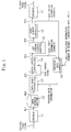
- Figure 1 illustrates a first exemplary video playback system to which the inventive digital decoding method is applicable.
- the system includes encoder 11 , data storage medium 12 , data read controller 13 , data input controller 14 , bit stream storage (buffer) 15 , data output controller 16 , decoder 17 and transfer rate controller 18 .
- encoded bit streams are identified by BS1 through BS6 , respectively.
- the system shown in Figure 1 is a so-called "codec" including both the encoder 11 and decoder 17 .
- the encoder 11 produces a bit stream BS1 by compressing and encoding an original video signal.
- the bit stream BS1 generated is recorded on the data storage medium 12 , which may be any recording medium like magneto-optical disk, magnetic tape or semiconductor memory.
- the data read controller 13 can read out a bit stream BS2 from the data storage medium 12 at a variable rate. Receiving a bit stream BS3 and a sync control signal from the data read controller 13 , the data input controller 14 writes a bit stream BS4 on the buffer 15 when the data read controller 13 reads the bit stream BS2 from the data storage medium 12 .
- the buffer 15 is a memory for temporarily storing the bit stream BS4 provided from the data input controller 14 .
- the data output controller 16 reads out a bit stream BS5 from the buffer 15 .
- the decoder 17 decodes a bit stream BS6 , which has been provided from the data output controller 16 , thereby outputting a decoded video signal.
- the transfer rate controller 18 calculates an occupancy level of the buffer 15 .
- the transfer rate controller 18 determines a read rate for the data storage medium 12 . Then, the controller 18 provides information about this rate to the data read controller 13 as transfer rate information.
- a bit rate at which the bit stream BS4 is input to the buffer 15 (which will be herein called a “buffer input rate”) is equal to the rate at which the bit stream BS2 is read out from the data storage medium 12 and is variable.
- a bit rate at which the decoder 17 decodes the bit stream BS6 (which will be herein called a “decode rate”) is equal to the rate at which each scene is encoded (i.e., a compression rate). It should be noted that part of a memory resource, shared by the encoder 11 , decoder 17 and other circuit blocks, is allocated to the buffer 15 .
- Figure 2 illustrates how the occupancy levels of the decoder buffer 15 shown in Figure 1 change with time.
- DI1, DI2 and DI3 denote intervals during which respective bit streams representing first, second and third scenes are input to the buffer 15.
- the second and third scene input intervals DI2 and DI3 start at times t20 and t30, respectively.
- Each scene is represented by one group of pictures (GOP), for example.
- the one-dot-chain line plots the changing occupancy levels of the buffer 15 when the buffer input rate is fixed at the same value Ri for every scene.
- the solid line plots the changing occupancy levels of the buffer 15 when the buffer input rates for the first, second and third scenes are set to Ri(1), Ri(2) and Ri(3), respectively.
- the gradient of a rightwardly increasing segment represents a buffer input rate and the length of a vertical segment represents the picture data quantity on a frame-by-frame basis.
- each unit of picture data is supposed to be removed from the buffer 15 instantaneously.
- Sv represents the size of a virtual buffer for use in bit rate control by the encoder 11, i.e., the size of a video buffering verifier (VBV) buffer as defined by the MPEG standards. That is to say, once data has been stored in the buffer 15 to the predetermined level Sv, decoding of the first frame can be started.
- the predetermined data level Sv is also equal to the maximum quantity of data that can be removed from the buffer 15 at a time.
- T shown in Figure 2 represents one frame period.
- T 33.3 ms.
- the occupancy level of the buffer 15 for the first scene reaches the predetermined level Sv. Accordingly, decoding of the first scene may be started at this time t11. Also, at a time t21 when the first frame of the second scene starts being decoded, the occupancy levels of the buffer 15 are equal to or greater than the predetermined level Sv for both cases represented by the one-dot-chain and solid lines. Thus, the second scene can be joined with the first scene seamlessly without causing the buffer 15 to underflow.
- the occupancy levels of the buffer 15 are equal to the predetermined level Sv for both cases represented by the one-dot-chain and solid lines.
- the third scene can also be joined with the second scene seamlessly without causing the buffer 15 to underflow.
- the data with the predetermined quantity Sv for the last frame of the first scene is removed from the buffer 15 and output to the decoder 17.
- the data of the second scene is input at the buffer input rate Ri.
- the occupancy level of the buffer 15 has been restored to the predetermined level Sv.
- the data with the predetermined quantity Sv for the first frame of the second scene is removed from the buffer 15 and output to the decoder 17 at the time t21.
- the occupancy level of the buffer 15 becomes zero at the time t21.
- the occupancy level of the buffer 15 at the time t20 before the data has been removed is given by 2 ⁇ Sv-Ri ⁇ T .
- Sb 2 ⁇ Sv-Ri ⁇ T the second scene can be joined with the first scene seamlessly without causing the buffer 15 to overflow or underflow.
- the total capacity Sb of the buffer 15 may be greater than 2 ⁇ Sv-Ri ⁇ T .
- data with the predetermined quantity Sv is also stored in the buffer 15 at the time t31 when decoding is started. Accordingly, the third scene can be joined with the second scene seamlessly without causing the buffer 15 to underflow.
- the power dissipated during the second scene input interval DI2 can be reduced.
- the system shown in Figure 1 controls the read rate for the data storage medium 12 based on the residual data quantity of the buffer 15 every time scenes are joined together, thereby realizing seamless presentation of multiple scenes using only the decoding section.
- the buffer input rate Ri(2) (i.e., the read rate for the data storage medium 12 ) for the second scene may also be controlled based on the residual data quantity ⁇ at the time t20 shown in Figure 2, i.e., the quantity of data left in the buffer 15 when the data for the last frame of the first scene is removed from the buffer 15 and output to the decoder 17.
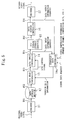
- Figure 3 illustrates a second exemplary video playback system to which the inventive digital decoding method is also applicable.
- the system includes encoder 11, data storage medium 12, data read controller 13, data input controller 14, bit stream storage (buffer) 15, data output controller 16, decoder 17 and decoding controller 19.
- encoded bit streams are also identified by BS1 through BS6, respectively.
- the system shown in Figure 3 is a so-called "codec” including both the encoder 11 and decoder 17.
- the encoder 11 produces a bit stream BS1 by compressing and encoding an original video signal.
- the bit stream BS1 generated is recorded on the data storage medium 12, which may be any recording medium like magneto-optical disk, magnetic tape or semiconductor memory.
- the data read controller 13 reads out a bit stream BS2 from the data storage medium 12 at a fixed rate.
- the data input controller 14 receives a bit stream BS3 from the data read controller 13.
- the buffer 15 is a memory with a variable capacity for temporarily storing a bit stream BS4 provided from the data input controller 14. Part of a memory resource, shared by the encoder 11, decoder 17 and other circuit blocks, is allocated to the buffer 15.
- the data output controller 16 reads out a bit stream BS5 from the buffer 15.
- the decoder 17 decodes a bit stream BS6, which has been provided from the data output controller 16, thereby outputting a decoded video signal.
- the decoding controller 19 estimates the occupancy level of the buffer 15 when the first frame of each scene starts being decoded.
- the decoding controller 19 If the estimated buffer occupancy level when a scene starts being decoded is less than the predetermined level Sv (i.e., the size of the VBV buffer), then the decoding controller 19 provides buffer size information to the data input and output controllers 14 and 16 instructing that the default capacity Sb of the buffer 15 (see Equation (1)), which was defined on the supposition that there will be no data quantity shortage, be increased by a data quantity deficit ⁇ . Then, the decoding controller 19 provides decode start information to the data output controller 16 instructing that decoding of the first frame of the first scene should not be started until the data of the first scene has been stored in the buffer 15 to the level equal to the sum of the predetermined level Sv and the deficit ⁇ . Also, by reference to the data input and output information provided from the data input and output controllers 14 and 16, i.e., information about write and read addresses at the buffer 15, the decoding controller 19 knows the occupancy level in the buffer 15.
- Figure 4 illustrates how the occupancy level of the buffer 15 shown in Figure 3 changes with time.
- a rate Ri at which the bit stream is input to the buffer 15 i.e., the buffer input rate
- the one-dot-chain line plots changing occupancy levels of the buffer 15 and represents that if the first frame of the first scene starts being decoded at a time t11, then the buffer 15 will underflow at a time t31'.
- the bit streams representing the first, second and third scenes are input to the buffer 15 over the intervals DI1', DI2' and DI3', respectively.
- the second and third scene input intervals DI2' and DI3' start at respective times t20' and t30'.
- the solid line plots changing occupancy levels of the buffer 15 and represents that if decoding of the first frame of the first scene is delayed until a time t12, then the buffer 15 will not underflow.
- the bit streams representing the first, second and third scenes are input to the buffer 15 over the intervals DI1, DI2 and DI3, respectively.
- the second and third scene input intervals DI2 and DI3 start at respective times t20 and t30.
- the occupancy level of the buffer 15 for the first scene reaches the predetermined level Sv as shown in Figure 4.
- the first frame of the first scene starts being decoded at the time t11.
- data with the predetermined quantity Sv is still stored in the buffer 15 at a time t21', which is one frame period T later than the time t20'.
- the occupancy level of the buffer 15 is lower than the predetermined level Sv by the deficit ⁇ at a time t31', which is one frame period T later than the time t30'.
- decoding of the first frame of the third scene cannot be started immediately but postponed until a time t32', when the data will be stored in the buffer 15 to the predetermined level Sv. That is to say, a so-called “VBV delay (or startup delay)" is caused between the times t31' and t32', and therefore the third scene cannot be joined with the second scene seamlessly.
- the seamless presentation might not be realizable unless some measure is taken, e.g., increasing the buffer input rate for the second scene (see Equation (3)).
- decoding of the first frame of the first scene is not started until a time t12, which is later than the time t11 by a period DT.
- start of decoding is intentionally delayed until the data of the first scene has been stored in the buffer 15 to a level equal to the sum of the predetermined level Sv and the deficit ⁇ that can be estimated by Equation (4).
- the buffer 15 will not underflow at the time t21 when the first frame of the second scene starts being decoded or the time t31 when the first frame of the third scene starts being decoded. That is to say, not only seamless joining of the second scene with the first but also such joining of the third with the second are realizable as well. It should be noted, however, that the total capacity of the buffer 15 should be increased up to Sb+ ⁇ so that the buffer 15 will not overflow.
- the system shown in Figure 3 realizes seamless presentation of multiple scenes using only the decoder section.
- the read rate for the data storage medium 12 is fixed and therefore the rate at which the bit stream is input to the buffer 15 (i.e., the buffer input rate) is also constant all through the scenes.
- the rates at which bit streams representing respective scenes are input to the buffer 15 may be controlled to some extent following the method shown in Figures 1 and 2 while adopting the method shown in Figures 3 and 4. In that case, the capacity increment ⁇ of the buffer 15 can be reduced.
- the next scene to be joined with the current scene seamlessly is supposed to be known in advance.
- an unexpected scene join request may be received while a scene is being presented.
- the video playback system to be described below can cope with even a situation like this.
- Figure 5 illustrates a third exemplary video playback system to which the inventive digital decoding method is also applicable.
- a transfer rate controller 18a shown in Figure 5 is different from the transfer rate controller 18 shown in Figure 1 in that the former controller 18a receives a scene join request.
- the other components shown in Figure 5 are the same as the counterparts shown in Figure 1.
- the transfer rate controller 18a shown in Figure 5 estimates an occupancy level of the buffer 15 when the first frame of the next scene to be joined starts being decoded. If the estimated occupancy level is less than the predetermined level Sv by a deficit ⁇ , then the transfer rate controller 18a controls the rate at which the remaining frames of the current scene will be read out from the data storage medium 12 to cover the data quantity deficit ⁇ .
- Figure 6 illustrates exemplary changing occupancy levels of the decoder buffer 15 shown in Figure 5.
- DI1, DI2 and DI3 denote intervals during which respective bit streams representing first, second and third scenes are input to the buffer 15.
- the second and third scene input intervals DI2 and DI3 start at times t20 and t30, respectively.
- a request that the third scene be joined with the second scene is received while the second scene is being presented.
- the one-dot-chain line shown in Figure 6 represents that if the buffer input rates Ri(1), Ri(2) and Ri(3) for the respective scenes are kept constant at Ri, then the buffer 15 will underflow at a time t31.
- the solid line shown in Figure 6 represents that if the buffer input rate Ri(2) for the second scene is increased to a maximum read rate Rimax for the data storage medium 12 for just a short period of time Te in response to the scene join request, then the buffer 15 will not underflow.
- the occupancy level of the buffer 15 is lower than the predetermined level Sv by the deficit ⁇ at a time t31, which is one frame period T later than the time t30.
- a time t32 when the data will be stored in the buffer 15 to the predetermined level Sv. That is to say, a startup delay is caused between the times t31 and t32, and therefore the third scene cannot be joined with the second scene seamlessly.
- the data quantity deficit ⁇ can be estimated by Equation (4).
- Figure 7 illustrates another exemplary changing occupancy levels of the buffer 15 shown in Figure 5.
- a request that the third scene be joined with the second scene is received while the second scene is being presented as in the example shown in Figure 6.
- the solid line shown in Figure 7 represents that if the buffer input rate Ri(2) (i.e., the read rate for the data storage medium 12 ) for the remaining frames of the second scene is increased to a rate Rie on average in response to the scene join request, then the buffer 15 will not underflow.
- Ri(2) i.e., the read rate for the data storage medium 12
- the buffer input rate Ri(2) for the second scene is increased to the rate Rie required for covering the data quantity deficit ⁇ for a plurality of frame periods starting at the time t22 when the scene join request is received. That is to say, if the number of remaining frames of the current scene (i.e., the second scene in this example) when the scene join request is received is denoted by Nr(2), then the remaining time available for reading the current scene from the data storage medium 12 is given by T ⁇ Nr(2).
- a rate Rie Ri + ⁇ /(T ⁇ Nr(2)) is adopted as a rate for reading out the remaining frames. Accordingly, as in the example shown in Figure 6, the third scene can also be joined with the second scene seamlessly without causing the buffer 15 to underflow.
Landscapes
- Engineering & Computer Science (AREA)
- Multimedia (AREA)
- Signal Processing (AREA)
- Business, Economics & Management (AREA)
- Marketing (AREA)
- Compression Or Coding Systems Of Tv Signals (AREA)
- Studio Devices (AREA)
- Signal Processing For Digital Recording And Reproducing (AREA)
- Television Signal Processing For Recording (AREA)
Abstract
Every time scenes should be joined, a read rate for a
data storage medium is controlled by reference to a buffer
occupancy level such that data is stored in the buffer to a
predetermined level or more when the first frame of each
scene starts being decoded. In this manner, seamless
presentation of multiple scenes is realizable by using only a
decoder section without resorting to an encoder section.
Description
- The present invention relates to a digital decoding method for sequentially decoding encoded bit streams, representing multiple scenes of a moving picture, such that those scenes can be presented seamlessly.
- MPEG standards are typical video compression standards issued by Moving Picture Experts Group. Japanese Laid-Open Publication No. 9-331524 discloses a digital encoding method for seamlessly joining multiple bit streams (representing respective scenes) to be encoded by the MPEG standards. In this method, to join a first scene seamlessly with a second scene without causing a decoder buffer to overflow or underflow, encoding bit rates (i.e., compression rates) are limited around the end of the first bit stream and around the start of the second bit stream.
- According to the prior art, however, the encoder section should prepare for seamless presentation of multiple scenes. Thus, scenes to be joined must be specified in advance. Also, in accordance with such a technique, the resultant image quality might vary even within a single scene.
- It is therefore an object of the present invention to realize seamless presentation of multiple scenes using only the decoder section and without resorting to the encoder section.
- To achieve this object, a first inventive method is applied to a digital decoding apparatus in which encoded bit streams, representing multiple scenes of a moving picture, are read out from a data storage medium and then input to a decoder by way of a buffer. In the first method, the bit streams are digitally decoded one after another to present the scenes seamlessly by controlling a rate at which a current scene is being read out from the data storage medium such that an occupancy level of the buffer will be a predetermined level or more when a first frame of a next scene starts being decoded.
- A second inventive method is applied to a digital decoding apparatus in which encoded bit streams, representing multiple scenes of a moving picture, are input to a decoder by way of a buffer. According to the second method, the bit streams are digitally decoded one after another to present the scenes seamlessly by performing the following steps. First, it is estimated how high an occupancy level of the buffer will be when a first frame of each scene starts being decoded. If the estimated buffer occupancy level when a scene starts being decoded is less than a predetermined level by a deficit, then start of decoding a first frame of a first scene is postponed until data of the first scene has been stored in the buffer to a level equal to a sum of the deficit and the predetermined level.
- A third inventive method is also applied to a digital decoding apparatus in which encoded bit streams, representing multiple scenes of a moving picture, are input to a decoder by way of a buffer. According to the third method, the bit streams are digitally decoded one after another to present the scenes seamlessly by performing the following steps. First, a rate at which each said bit stream, associated with one of the scenes, is input to the buffer is controlled to no greater than a certain limit. Then, it is estimated how high an occupancy level of the buffer will be when a first frame of each scene starts being decoded. If the estimated buffer occupancy level when a scene starts being decoded is less than a predetermined level by a deficit, then start of decoding a first frame of a first scene is postponed until data of the first scene has been stored in the buffer to a level equal to a sum of the deficit and the predetermined level.
-
- Figure 1 is a block diagram illustrating a first exemplary video playback system to which the inventive digital decoding method is applicable.
- Figure 2 is a timing diagram illustrating how the occupancy level of the bit stream storage (buffer) shown in Figure 1 changes with time.
- Figure 3 is a block diagram illustrating a second exemplary video playback system to which the inventive digital decoding method is also applicable.
- Figure 4 is a timing diagram illustrating how the occupancy level of the bit stream storage (buffer) shown in Figure 3 changes with time.
- Figure 5 is a block diagram illustrating a third exemplary video playback system to which the inventive digital decoding method is also applicable.
- Figures 6 and 7 are timing diagrams illustrating how the occupancy level of the bit stream storage (buffer) shown in Figure 5 may change with time.
-
- Figure 1 illustrates a first exemplary video playback system to which the inventive digital decoding method is applicable. As shown in Figure 1, the system includes
encoder 11,data storage medium 12, data readcontroller 13,data input controller 14, bit stream storage (buffer) 15,data output controller 16,decoder 17 andtransfer rate controller 18. In Figure 1, encoded bit streams are identified by BS1 through BS6, respectively. - The system shown in Figure 1 is a so-called "codec" including both the
encoder 11 anddecoder 17. Theencoder 11 produces a bit stream BS1 by compressing and encoding an original video signal. The bit stream BS1 generated is recorded on thedata storage medium 12, which may be any recording medium like magneto-optical disk, magnetic tape or semiconductor memory. Thedata read controller 13 can read out a bit stream BS2 from thedata storage medium 12 at a variable rate. Receiving a bit stream BS3 and a sync control signal from thedata read controller 13, thedata input controller 14 writes a bit stream BS4 on thebuffer 15 when the data readcontroller 13 reads the bit stream BS2 from thedata storage medium 12. Thebuffer 15 is a memory for temporarily storing the bit stream BS4 provided from thedata input controller 14. Thedata output controller 16 reads out a bit stream BS5 from thebuffer 15. Thedecoder 17 decodes a bit stream BS6, which has been provided from thedata output controller 16, thereby outputting a decoded video signal. By reference to data input and output information provided from the data input andoutput controllers buffer 15, thetransfer rate controller 18 calculates an occupancy level of thebuffer 15. Then, based on the information obtained about the occupancy level of thebuffer 15 and video compression information about the number of frames in each scene, a compression rate, etc., thetransfer rate controller 18 determines a read rate for thedata storage medium 12. Then, thecontroller 18 provides information about this rate to the data readcontroller 13 as transfer rate information. - In this case, a bit rate at which the bit stream BS4 is input to the buffer 15 (which will be herein called a "buffer input rate") is equal to the rate at which the bit stream BS2 is read out from the
data storage medium 12 and is variable. Also, a bit rate at which thedecoder 17 decodes the bit stream BS6 (which will be herein called a "decode rate") is equal to the rate at which each scene is encoded (i.e., a compression rate). It should be noted that part of a memory resource, shared by theencoder 11,decoder 17 and other circuit blocks, is allocated to thebuffer 15. - Figure 2 illustrates how the occupancy levels of the
decoder buffer 15 shown in Figure 1 change with time. In Figure 2, DI1, DI2 and DI3 denote intervals during which respective bit streams representing first, second and third scenes are input to thebuffer 15. The second and third scene input intervals DI2 and DI3 start at times t20 and t30, respectively. Each scene is represented by one group of pictures (GOP), for example. In Figure 2, the one-dot-chain line plots the changing occupancy levels of thebuffer 15 when the buffer input rate is fixed at the same value Ri for every scene. On the other hand, the solid line plots the changing occupancy levels of thebuffer 15 when the buffer input rates for the first, second and third scenes are set to Ri(1), Ri(2) and Ri(3), respectively. In these lines, the gradient of a rightwardly increasing segment represents a buffer input rate and the length of a vertical segment represents the picture data quantity on a frame-by-frame basis. In the illustrated example, each unit of picture data is supposed to be removed from thebuffer 15 instantaneously. - In Figure 2, Sv represents the size of a virtual buffer for use in bit rate control by the
encoder 11, i.e., the size of a video buffering verifier (VBV) buffer as defined by the MPEG standards. That is to say, once data has been stored in thebuffer 15 to the predetermined level Sv, decoding of the first frame can be started. The predetermined data level Sv is also equal to the maximum quantity of data that can be removed from thebuffer 15 at a time. - T shown in Figure 2 represents one frame period. For example, according to the NTSC (National Television System Committee) video rate (i.e., 30 frames per second), T=33.3 ms.
- As shown in Figure 2, at a time t11 that is later than a time t10 by one frame period T, the occupancy level of the
buffer 15 for the first scene reaches the predetermined level Sv. Accordingly, decoding of the first scene may be started at this time t11. Also, at a time t21 when the first frame of the second scene starts being decoded, the occupancy levels of thebuffer 15 are equal to or greater than the predetermined level Sv for both cases represented by the one-dot-chain and solid lines. Thus, the second scene can be joined with the first scene seamlessly without causing thebuffer 15 to underflow. Furthermore, at a time t31 when the first frame of the third scene starts being decoded, the occupancy levels of thebuffer 15 are equal to the predetermined level Sv for both cases represented by the one-dot-chain and solid lines. Thus, the third scene can also be joined with the second scene seamlessly without causing thebuffer 15 to underflow. - The case plotted by the one-dot-chain line in Figure 2 will be described in detail. At the time t20, the data with the predetermined quantity Sv for the last frame of the first scene is removed from the
buffer 15 and output to thedecoder 17. During subsequent one frame period T, the data of the second scene is input at the buffer input rate Ri. Thus, at the time t21, the occupancy level of thebuffer 15 has been restored to the predetermined level Sv. Accordingly, the data with the predetermined quantity Sv for the first frame of the second scene is removed from thebuffer 15 and output to thedecoder 17 at the time t21. As a result, the occupancy level of thebuffer 15 becomes zero at the time t21. That is to say, the occupancy level of thebuffer 15 at the time t20 before the data has been removed is given bybuffer 15 twice consecutively, if the total capacity Sb of thebuffer 15 meet the condition given by the following Equation (1):buffer 15 to overflow or underflow. Naturally, the total capacity Sb of thebuffer 15 may be greater than - As also can be seen front the one-dot-chain plot shown in Figure 2, to attain the predetermined level Sv at the time t31 such that the third scene can be joined seamlessly with the second scene, the occupancy level of the
buffer 15 should be increased from zero to the predetermined level Sv at a rate of Ri-Re(2) within a period of time T×N(2) between the times t21 and t31, where N(2) is the number of frames in the second scene and Re(2) is an encoding bit rate (compression rate) for the second scene. That is to say, the buffer input rate Ri should be set so as to meet the following Equation (2): - Specifically, supposing Sv=1.835 Mbit, T=33.3 ms, N(2) =15 and Re(2)= 8 Mbps, Ri = 11.67 Mbps and Sb =3.281 Mbit according to Equations (2) and (1), respectively. That is to say, by setting the total capacity Sb of the
buffer 15 to 3.281 Mbit or more and the buffer input rate Ri (i.e., the read rate for the data storage medium 12) to 11.67 Mbps, the bit streams representing these three scenes can be decoded one after another so as to present these scenes seamlessly without causing thebuffer 15 to overflow or underflow. - As for a case plotted by the solid line in Figure 2, data for the last frame of the first scene with a quantity smaller than the predetermined quantity Sv is removed at the time t20 from the
buffer 15 with its total capacity Sb filled with data and then output to thedecoder 17. During the subsequent one frame period T, data for the second scene is input to restore the occupancy level of thebuffer 15 to more than the predetermined level Sv. Thus, at the time t21 when the data with the predetermined quantity Sv for the first frame of the second scene is removed from thebuffer 15 and output to thedecoder 17, data with a quantity α ( > 0) is still left in thebuffer 15. Using this residual data quantity α, thetransfer rate controller 18 controls the buffer input rate Ri(2) (i.e., the read rate for the data storage medium 12) for the second scene in accordance with the following Equation (3):buffer 15 at the time t31 when the first frame of the third scene starts being decoded will be equal to the predetermined level Sv. In this case, data with the predetermined quantity Sv is also stored in thebuffer 15 at the time t31 when decoding is started. Accordingly, the third scene can be joined with the second scene seamlessly without causing thebuffer 15 to underflow. In addition, supposing α=0.5 Mbit under the same conditions as the one-dot-chain plot, Ri(2) = 10.67 Mbps according to Equation (3). Thus, the power dissipated during the second scene input interval DI2 can be reduced. - As can be seen, the system shown in Figure 1 controls the read rate for the
data storage medium 12 based on the residual data quantity of thebuffer 15 every time scenes are joined together, thereby realizing seamless presentation of multiple scenes using only the decoding section. - Optionally, the buffer input rate Ri(2) (i.e., the read rate for the data storage medium 12) for the second scene may also be controlled based on the residual data quantity β at the time t20 shown in Figure 2, i.e., the quantity of data left in the
buffer 15 when the data for the last frame of the first scene is removed from thebuffer 15 and output to thedecoder 17. - Figure 3 illustrates a second exemplary video playback system to which the inventive digital decoding method is also applicable. As shown in Figure 3, the system includes
encoder 11,data storage medium 12, data readcontroller 13,data input controller 14, bit stream storage (buffer) 15,data output controller 16,decoder 17 anddecoding controller 19. In Figure 3, encoded bit streams are also identified by BS1 through BS6, respectively. - The system shown in Figure 3 is a so-called "codec" including both the
encoder 11 anddecoder 17. Theencoder 11 produces a bit stream BS1 by compressing and encoding an original video signal. The bit stream BS1 generated is recorded on thedata storage medium 12, which may be any recording medium like magneto-optical disk, magnetic tape or semiconductor memory. The data readcontroller 13 reads out a bit stream BS2 from thedata storage medium 12 at a fixed rate. Thedata input controller 14 receives a bit stream BS3 from the data readcontroller 13. Thebuffer 15 is a memory with a variable capacity for temporarily storing a bit stream BS4 provided from thedata input controller 14. Part of a memory resource, shared by theencoder 11,decoder 17 and other circuit blocks, is allocated to thebuffer 15. Thedata output controller 16 reads out a bit stream BS5 from thebuffer 15. Thedecoder 17 decodes a bit stream BS6, which has been provided from thedata output controller 16, thereby outputting a decoded video signal. By reference to video compression information about the number of frames in each scene, compression rate, etc. and presentation information about the order of scenes presented, etc., thedecoding controller 19 estimates the occupancy level of thebuffer 15 when the first frame of each scene starts being decoded. If the estimated buffer occupancy level when a scene starts being decoded is less than the predetermined level Sv (i.e., the size of the VBV buffer), then thedecoding controller 19 provides buffer size information to the data input andoutput controllers decoding controller 19 provides decode start information to thedata output controller 16 instructing that decoding of the first frame of the first scene should not be started until the data of the first scene has been stored in thebuffer 15 to the level equal to the sum of the predetermined level Sv and the deficit γ. Also, by reference to the data input and output information provided from the data input andoutput controllers buffer 15, thedecoding controller 19 knows the occupancy level in thebuffer 15. - Figure 4 illustrates how the occupancy level of the
buffer 15 shown in Figure 3 changes with time. In this case, a rate Ri at which the bit stream is input to the buffer 15 (i.e., the buffer input rate) is constant throughout the scenes. In Figure 4, the one-dot-chain line plots changing occupancy levels of thebuffer 15 and represents that if the first frame of the first scene starts being decoded at a time t11, then thebuffer 15 will underflow at a time t31'. In that case, the bit streams representing the first, second and third scenes are input to thebuffer 15 over the intervals DI1', DI2' and DI3', respectively. As shown in Figure 4, the second and third scene input intervals DI2' and DI3' start at respective times t20' and t30'. In Figure 4, the solid line plots changing occupancy levels of thebuffer 15 and represents that if decoding of the first frame of the first scene is delayed until a time t12, then thebuffer 15 will not underflow. In that case, the bit streams representing the first, second and third scenes are input to thebuffer 15 over the intervals DI1, DI2 and DI3, respectively. As shown in Figure 4, the second and third scene input intervals DI2 and DI3 start at respective times t20 and t30. - At a time t11, which is one frame period T later than the time t10, the occupancy level of the
buffer 15 for the first scene reaches the predetermined level Sv as shown in Figure 4. According to the decoding process as represented by the one-dot-chain line plot, the first frame of the first scene starts being decoded at the time t11. Even so, data with the predetermined quantity Sv is still stored in thebuffer 15 at a time t21', which is one frame period T later than the time t20'. Thus, decoding of the first frame of the second scene can be started immediately. However, the occupancy level of thebuffer 15 is lower than the predetermined level Sv by the deficit γ at a time t31', which is one frame period T later than the time t30'. Accordingly, decoding of the first frame of the third scene cannot be started immediately but postponed until a time t32', when the data will be stored in thebuffer 15 to the predetermined level Sv. That is to say, a so-called "VBV delay (or startup delay)" is caused between the times t31' and t32', and therefore the third scene cannot be joined with the second scene seamlessly. For example, if the encoding bit rate for the second scene is rather high, the seamless presentation might not be realizable unless some measure is taken, e.g., increasing the buffer input rate for the second scene (see Equation (3)). - The data quantity deficit γ can be estimated as:
- According to the decoding process as represented by the solid-line plot in Figure 4, decoding of the first frame of the first scene is not started until a time t12, which is later than the time t11 by a period DT. In other words, start of decoding is intentionally delayed until the data of the first scene has been stored in the
buffer 15 to a level equal to the sum of the predetermined level Sv and the deficit γ that can be estimated by Equation (4). As a result, thebuffer 15 will not underflow at the time t21 when the first frame of the second scene starts being decoded or the time t31 when the first frame of the third scene starts being decoded. That is to say, not only seamless joining of the second scene with the first but also such joining of the third with the second are realizable as well. It should be noted, however, that the total capacity of thebuffer 15 should be increased up to Sb+γ so that thebuffer 15 will not overflow. - By delaying the start of decoding of a first scene in accordance with the estimated deficit γ in this manner, the system shown in Figure 3 realizes seamless presentation of multiple scenes using only the decoder section.
- In the example illustrated in Figure 3, the read rate for the
data storage medium 12 is fixed and therefore the rate at which the bit stream is input to the buffer 15 (i.e., the buffer input rate) is also constant all through the scenes. However, if the read rate for thedata storage medium 12 is changeable up to its upper-limit, the rates at which bit streams representing respective scenes are input to thebuffer 15 may be controlled to some extent following the method shown in Figures 1 and 2 while adopting the method shown in Figures 3 and 4. In that case, the capacity increment γ of thebuffer 15 can be reduced. - Also, by increasing the capacity of the
buffer 15 in advance by the deficit required while taking the number of scenes to be joined and encoding bit rates and the number of frames of respective scenes into account, four or more scenes can be joined with each other seamlessly. - In the first and second video playback systems, the next scene to be joined with the current scene seamlessly is supposed to be known in advance. However, an unexpected scene join request may be received while a scene is being presented. The video playback system to be described below can cope with even a situation like this.
- Figure 5 illustrates a third exemplary video playback system to which the inventive digital decoding method is also applicable. A
transfer rate controller 18a shown in Figure 5 is different from thetransfer rate controller 18 shown in Figure 1 in that theformer controller 18a receives a scene join request. The other components shown in Figure 5 are the same as the counterparts shown in Figure 1. - Responsive to a scene join request received while the current scene is being presented, the
transfer rate controller 18a shown in Figure 5 estimates an occupancy level of thebuffer 15 when the first frame of the next scene to be joined starts being decoded. If the estimated occupancy level is less than the predetermined level Sv by a deficit γ, then thetransfer rate controller 18a controls the rate at which the remaining frames of the current scene will be read out from thedata storage medium 12 to cover the data quantity deficit γ. - Figure 6 illustrates exemplary changing occupancy levels of the
decoder buffer 15 shown in Figure 5. In Figure 6, DI1, DI2 and DI3 denote intervals during which respective bit streams representing first, second and third scenes are input to thebuffer 15. The second and third scene input intervals DI2 and DI3 start at times t20 and t30, respectively. In this case, a request that the third scene be joined with the second scene is received while the second scene is being presented. The one-dot-chain line shown in Figure 6 represents that if the buffer input rates Ri(1), Ri(2) and Ri(3) for the respective scenes are kept constant at Ri, then thebuffer 15 will underflow at a time t31. On the other hand, the solid line shown in Figure 6 represents that if the buffer input rate Ri(2) for the second scene is increased to a maximum read rate Rimax for thedata storage medium 12 for just a short period of time Te in response to the scene join request, then thebuffer 15 will not underflow. - According to the decoding process as plotted by the one-dot-chain line in Figure 6, the occupancy level of the
buffer 15 is lower than the predetermined level Sv by the deficit γ at a time t31, which is one frame period T later than the time t30. Thus, decoding of the first frame of the third scene cannot be started immediately but postponed until a time t32, when the data will be stored in thebuffer 15 to the predetermined level Sv. That is to say, a startup delay is caused between the times t31 and t32, and therefore the third scene cannot be joined with the second scene seamlessly. In this case, the data quantity deficit γ can be estimated by Equation (4). - In contrast, in the decoding process as represented by the solid line in Figure 6, the buffer input rate Ri(2) for the second scene (i.e., the read rate for the data storage medium 12) is increased to the maximum rate Rimax for just a short period Te of time needed for covering the data quantity deficit γ during the one frame period T starting at the time t22 when the scene join request is received. That is to say, the buffer input rate Ri(2) is raised for the period Te meeting the following Equation (5):
buffer 15 to underflow. - Figure 7 illustrates another exemplary changing occupancy levels of the
buffer 15 shown in Figure 5. Suppose a request that the third scene be joined with the second scene is received while the second scene is being presented as in the example shown in Figure 6. The solid line shown in Figure 7 represents that if the buffer input rate Ri(2) (i.e., the read rate for the data storage medium 12) for the remaining frames of the second scene is increased to a rate Rie on average in response to the scene join request, then thebuffer 15 will not underflow. - According to the decoding process as represented by the solid line in Figure 7, the buffer input rate Ri(2) for the second scene is increased to the rate Rie required for covering the data quantity deficit γ for a plurality of frame periods starting at the time t22 when the scene join request is received. That is to say, if the number of remaining frames of the current scene (i.e., the second scene in this example) when the scene join request is received is denoted by Nr(2), then the remaining time available for reading the current scene from the
data storage medium 12 is given by T × Nr(2). Thus, a rate Rie given by the following Equation (6):buffer 15 to underflow. - In this manner, by controlling the rate for reading out the remaining frames of the current scene from the
data storage medium 12 in accordance with the data quantity deficit γ that is estimated when a scene join request is received, the system shown in Figure 5 realizes seamless presentation of multiple scenes using only the decoder section. - Since Te <T in the example shown in Figure 6, the read rate is controlled for just one of the remaining frames of the second scene. However, if T < Te <2T, for example, the read rates of two frames should be controlled.
Claims (14)
- In a digital decoding apparatus in which encoded bit streams, representing multiple scenes of a moving picture, are read out from a data storage medium and then input to a decoder by way of a buffer, a method of digitally decoding the bit streams one after another to present the scenes seamlessly,the method comprising the steps of:controlling a rate at which a current scene is being read out from the data storage medium such that an occupancy level of the buffer will be a predetermined level or more when a first frame of a next scene starts being decoded; anddecoding the encoded bit streams provided from the buffer.
- The method of Claim 1, further comprising the step of controlling the rate at which the current scene is being read out from the data storage medium by reference to an occupancy level of the buffer at a point in time data of a first frame of the current scene was output from the buffer to the decoder.
- The method of Claim 1, further comprising the step of controlling the rate at which the current scene is being read out from the data storage medium by reference to an occupancy level of the buffer at a point in time data of a last frame of a previous scene, preceding the current scene, was output from the buffer to the decoder.
- The method of Claim 1, further comprising the steps of:in response to a scene join request received while the current scene is being presented, estimating how high an occupancy level of the buffer will be when a first frame of a next scene to be joined with the current scene starts being decoded; andif the estimated buffer occupancy level when the next scene starts being decoded is less than the predetermined level by a deficit,controlling a rate at which remaining frames of the current scene will be read out from the data storage medium so as to cover the deficit.
- The method of Claim 4, further comprising the step of maximizing the rate at which the scenes are read out from the data storage medium until the deficit has been eliminated.
- The method of Claim 4, further comprising the steps of:obtaining an increment, by which the read rate should be raised, by dividing the deficit by residual time available for reading out the current scene from the data storage medium; andraising the rate at which the remaining frames of the current scene will be read out from the data storage medium by the increment.
- In a digital decoding apparatus in which encoded bit streams, representing multiple scenes of a moving picture, are input to a decoder by way of a buffer, a method of digitally decoding the bit streams one after another to present the scenes seamlessly,the method comprising the steps of:estimating how high an occupancy level of the buffer will be when a first frame of each said scene starts being decoded; andif the estimated buffer occupancy level when a scene starts being decoded is less than a predetermined level by a deficit,postponing start of decoding a first frame of a first scene until data of the first scene has been stored in the buffer to a level equal to a sum of the deficit and the predetermined level.
- The method of Claim 7, further comprising the step of increasing a default capacity of the buffer by the deficit, the default capacity being defined on the supposition that the buffer occupancy level will not be less than the predetermined level.
- The method of Claim 8, further comprising the step of determining, by reference to a difference in compression rate between two consecutive scenes and a ratio of the number of frames included in one of these two scenes to that of the other, how much the default capacity of the buffer should be increased.
- In a digital decoding apparatus in which encoded bit streams, representing multiple scenes of a moving picture, are input to a decoder by way of a buffer, a method of digitally decoding the bit streams one after another to present the scenes seamlessly,the method comprising the steps of:controlling a rate at which each said bit stream, associated with one of the scenes, is input to the buffer to no greater than a certain limit, and then estimating how high an occupancy level of the buffer will be when a first frame of each said scene starts being decoded; andif the estimated buffer occupancy level when a scene starts being decoded is less than a predetermined level by a deficit,postponing start of decoding a first frame of a first scene until data of the first scene has been stored in the buffer to a level equal to a sum of the deficit and the predetermined level.
- The method of Claim 10, further comprising the step of controlling the rate at which each said bit stream, associated with one of the scenes, is input to the buffer by reference to an estimated occupancy level of the buffer when data of a first frame of each said scene is output from the buffer to the decoder.
- The method of Claim 10, further comprising the step of controlling the rate at which each said bit stream, associated with one of the scenes, is input to the buffer by reference to an estimated occupancy level of the buffer when data of a last frame of a previous scene, preceding a current scene, is output from the buffer to the decoder.
- The method of Claim 10, further comprising the step of increasing a default capacity of the buffer by the deficit, the default capacity being defined on the supposition that the buffer occupancy level will not be less than the predetermined level.
- The method of Claim 13, further comprising the step of determining, by reference to a difference in compression rate between two consecutive scenes and a ratio of the number of frames included in one of these two scenes to that of the other, how much the default capacity of the buffer should be increased.
Applications Claiming Priority (2)
| Application Number | Priority Date | Filing Date | Title |
|---|---|---|---|
| JP18278599 | 1999-06-29 | ||
| JP18278599 | 1999-06-29 |
Publications (1)
| Publication Number | Publication Date |
|---|---|
| EP1067793A2 true EP1067793A2 (en) | 2001-01-10 |
Family
ID=16124386
Family Applications (1)
| Application Number | Title | Priority Date | Filing Date |
|---|---|---|---|
| EP00113729A Withdrawn EP1067793A2 (en) | 1999-06-29 | 2000-06-28 | Digital video decoding method |
Country Status (3)
| Country | Link |
|---|---|
| EP (1) | EP1067793A2 (en) |
| KR (1) | KR20010007567A (en) |
| CN (2) | CN1555195A (en) |
Cited By (2)
| Publication number | Priority date | Publication date | Assignee | Title |
|---|---|---|---|---|
| US8233781B2 (en) * | 2004-09-01 | 2012-07-31 | Panasonic Corporation | Image reproduction method and image reproduction apparatus |
| CN104683866A (en) * | 2013-11-29 | 2015-06-03 | 成都鼎桥通信技术有限公司 | Playing processing method for received streaming video |
Families Citing this family (1)
| Publication number | Priority date | Publication date | Assignee | Title |
|---|---|---|---|---|
| JP4632698B2 (en) * | 2004-06-23 | 2011-02-16 | 日本電気株式会社 | Videophone device, image recording method used therefor, and program thereof |
-
2000
- 2000-06-20 CN CNA2004100633477A patent/CN1555195A/en active Pending
- 2000-06-20 CN CNB00109680XA patent/CN1164118C/en not_active Expired - Fee Related
- 2000-06-28 EP EP00113729A patent/EP1067793A2/en not_active Withdrawn
- 2000-06-29 KR KR1020000036283A patent/KR20010007567A/en not_active Ceased
Cited By (2)
| Publication number | Priority date | Publication date | Assignee | Title |
|---|---|---|---|---|
| US8233781B2 (en) * | 2004-09-01 | 2012-07-31 | Panasonic Corporation | Image reproduction method and image reproduction apparatus |
| CN104683866A (en) * | 2013-11-29 | 2015-06-03 | 成都鼎桥通信技术有限公司 | Playing processing method for received streaming video |
Also Published As
| Publication number | Publication date |
|---|---|
| KR20010007567A (en) | 2001-01-26 |
| CN1164118C (en) | 2004-08-25 |
| CN1283928A (en) | 2001-02-14 |
| CN1555195A (en) | 2004-12-15 |
Similar Documents
| Publication | Publication Date | Title |
|---|---|---|
| US5754241A (en) | Video decoder capable of controlling encoded video data | |
| US6327421B1 (en) | Multiple speed fast forward/rewind compressed video delivery system | |
| US6188700B1 (en) | Method and apparatus for encoding MPEG signals using variable rate encoding and dynamically varying transmission buffers | |
| KR100407085B1 (en) | Buffer management in variable bit-rate compression systems | |
| JP2002510947A (en) | Burst data transmission of compressed video data | |
| JPWO1999005864A1 (en) | Editing device, editing method, splicing device, splicing method, encoding device and encoding method | |
| US6314139B1 (en) | Method of inserting editable point and encoder apparatus applying the same | |
| US6240137B1 (en) | Encoding apparatus and method, decoding apparatus and method, and editing method | |
| KR19990007312A (en) | Digital signal coding method and apparatus, signal recording medium and signal transmission method | |
| US7333711B2 (en) | Data distribution apparatus and method, and data distribution system | |
| US9615095B2 (en) | Coding device, imaging device, coding transmission system, and coding method | |
| KR100975170B1 (en) | Image data reproducing apparatus and method | |
| US8009741B2 (en) | Command packet system and method supporting improved trick mode performance in video decoding systems | |
| US5760847A (en) | Processing moving image data based on an arbitrarily designated frame | |
| EP1067793A2 (en) | Digital video decoding method | |
| JP3839911B2 (en) | Image processing apparatus and image processing method | |
| JP2006203910A (en) | Method for transmitting data without jitter in a synchronized Ethernet system | |
| EP1773065A2 (en) | Signal encoding apparatus and method using 2-pass variable bit rate encoding | |
| US7006570B2 (en) | Video signal coding method and video signal encoder | |
| JP5046907B2 (en) | Recording apparatus, control method therefor, and program | |
| JP3982354B2 (en) | Image data reproducing apparatus and method | |
| JP3443391B2 (en) | Digital decoding method | |
| JP4064604B2 (en) | Image processing method and apparatus | |
| JP3338426B2 (en) | MPEG video decoder | |
| JP2983851B2 (en) | Digital video and digital audio playback device |
Legal Events
| Date | Code | Title | Description |
|---|---|---|---|
| PUAI | Public reference made under article 153(3) epc to a published international application that has entered the european phase |
Free format text: ORIGINAL CODE: 0009012 |
|
| AK | Designated contracting states |
Kind code of ref document: A2 Designated state(s): AT BE CH CY DE DK ES FI FR GB GR IE IT LI LU MC NL PT SE |
|
| AX | Request for extension of the european patent |
Free format text: AL;LT;LV;MK;RO;SI |
|
| RAP1 | Party data changed (applicant data changed or rights of an application transferred) |
Owner name: PANASONIC CORPORATION |
|
| STAA | Information on the status of an ep patent application or granted ep patent |
Free format text: STATUS: THE APPLICATION HAS BEEN WITHDRAWN |
|
| 18W | Application withdrawn |
Effective date: 20111108 |