JP5046907B2 - Recording apparatus, control method therefor, and program - Google Patents
Recording apparatus, control method therefor, and program Download PDFInfo
- Publication number
- JP5046907B2 JP5046907B2 JP2007325209A JP2007325209A JP5046907B2 JP 5046907 B2 JP5046907 B2 JP 5046907B2 JP 2007325209 A JP2007325209 A JP 2007325209A JP 2007325209 A JP2007325209 A JP 2007325209A JP 5046907 B2 JP5046907 B2 JP 5046907B2
- Authority
- JP
- Japan
- Prior art keywords
- stream
- picture
- video
- amount
- multiplexed stream
- Prior art date
- Legal status (The legal status is an assumption and is not a legal conclusion. Google has not performed a legal analysis and makes no representation as to the accuracy of the status listed.)
- Expired - Fee Related
Links
Images


Description
本発明は、動画像を記録媒体に記録する記録装置、その制御方法、及びプログラムに関する。 The present invention relates to a recording apparatus that records a moving image on a recording medium, a control method thereof, and a program.
現在、撮像した動画像をDVD−R等のディスク状の記録媒体に記録するビデオカメラが普及している。ディスク状の記録媒体を用いるビデオカメラは、小型で持ち運びも容易であり、今後ますます広く普及していくと思われる。このようなビデオカメラでは、動画像データの記録時には、例えばMPEG−2方式に従って、圧縮符号化された映像ストリーム及び音声ストリームを多重化した多重化ストリームを記録媒体に記録する。 At present, video cameras that record captured moving images on a disc-shaped recording medium such as a DVD-R are widely used. Video cameras that use disc-shaped recording media are small and easy to carry, and are expected to become increasingly popular in the future. In such a video camera, when recording moving image data, a multiplexed stream obtained by multiplexing a compression-encoded video stream and audio stream is recorded on a recording medium in accordance with, for example, the MPEG-2 system.
記録媒体に映像データ及び音声データを記録する規格として、DVD−Video規格が知られている。DVD−Video規格では、動画像データをMPEG−2方式で符号化して記録している。MPEG−2方式では、信号処理回路において、符号化部と復号化部との間にVBV(Video Buffering Verifier)バッファと呼ばれる仮想バッファを想定し、このVBVバッファが破綻しないように符号化を行うよう規定されている。 The DVD-Video standard is known as a standard for recording video data and audio data on a recording medium. In the DVD-Video standard, moving image data is encoded and recorded by the MPEG-2 system. In the MPEG-2 system, in a signal processing circuit, a virtual buffer called a VBV (Video Buffering Verifier) buffer is assumed between the encoding unit and the decoding unit, and encoding is performed so that the VBV buffer does not fail. It is prescribed.
ビデオカメラで動画像データを撮像する場合、断続的な撮像、即ち、撮像、一時停止、撮像、一時停止、撮像、、、の繰り返しが行われる場合が多い。このように断続的に撮像された動画像データは、一般的に、チャプタと呼ばれる単位で記録媒体に記録される。独立して記録された複数のチャプタを連続して再生すると、チャプタ間でフレームがスムーズに切り替わらず、再生が一瞬途切れる場合がある。そこで、チャプタ間で再生が途切れないように先行チャプタと後続チャプタとを接続する技術(所謂「シームレス接続」)が知られている。 When moving image data is captured by a video camera, intermittent imaging, that is, imaging, pause, imaging, pause, imaging, is often repeated. The moving image data captured intermittently in this way is generally recorded on a recording medium in units called chapters. If a plurality of chapters recorded independently are continuously played back, the frames may not be switched smoothly between chapters, and playback may be interrupted momentarily. Therefore, a technique (so-called “seamless connection”) is known in which a preceding chapter and a succeeding chapter are connected so that reproduction is not interrupted between chapters.
VBVバッファの占有量の遷移を考慮せずに2つのチャプタに対してシームレス接続を適用すると、VBVバッファが破綻する可能性がある。具体的には、後続チャプタの先頭ピクチャの復号時刻に、その先頭ピクチャの復号に必要な量のデータがVBVバッファに溜まっておらず、その結果、バッファアンダーフローが発生する可能性がある。 If seamless connection is applied to two chapters without considering the transition of the occupation amount of the VBV buffer, the VBV buffer may fail. Specifically, the amount of data necessary for decoding the leading picture is not accumulated in the VBV buffer at the decoding time of the leading picture of the subsequent chapter, and as a result, a buffer underflow may occur.
VBVバッファの破綻を防止するため、従来のシームレス接続においては、後続チャプタの先頭ピクチャに割り当てる符号量Cが、次の式1におけるCmax以下に制限されている。 In order to prevent the VBV buffer from failing, in the conventional seamless connection, the code amount C allocated to the head picture of the subsequent chapter is limited to Cmax or less in the following equation 1.
Cmax=(T2−T1)×Rmax (式1)
ここで、
T1:先行チャプタのVBVバッファに対する入力の終了時刻
T2:後続チャプタの先頭ピクチャの復号時刻
Rmax:VBVバッファに映像データが入力される速度
である。
Cmax = (T2-T1) * Rmax (Formula 1)
here,
T1: Input end time to the VBV buffer of the preceding chapter T2: Decoding time of the leading picture of the subsequent chapter Rmax: Speed at which video data is input to the VBV buffer.
なお、MPEG−2方式では、Rmaxは、例えば約9Mbpsに設定され、この値は、多重化ストリームにおける読み出し対象のデータの種類に関わらず一定である。即ち、多重化ストリームから映像データ以外のデータ(例えば、音声データ)が読み出されている間も、映像データは速度RmaxでVBVバッファに入力される。 In the MPEG-2 system, Rmax is set to about 9 Mbps, for example, and this value is constant regardless of the type of data to be read in the multiplexed stream. That is, while data other than video data (for example, audio data) is being read from the multiplexed stream, the video data is input to the VBV buffer at a speed Rmax.
また、特許文献1に開示されているように、VBVバッファを破綻させずにチャプタ間をシームレス接続させるために、記録時に後続の映像ストリーム(後続チャプタ)の先頭ピクチャの符号量を調整する技術が提案されている。
式1において、通常、T2−T1は比較的短時間であるため、Cmaxは比較的小さな値を取る。そのため、後続チャプタの先頭ピクチャに割り当てる符号量CをCmax以下に制限すると、後続チャプタの先頭ピクチャの画質が低下する。また、先頭ピクチャ以降のピクチャについても、VBVバッファが破綻しないように符号量を割り当てる必要があるため、低画質のピクチャが続く可能性がある。 In Equation 1, since T2-T1 is usually a relatively short time, Cmax takes a relatively small value. Therefore, if the code amount C assigned to the head picture of the subsequent chapter is limited to Cmax or less, the image quality of the head picture of the subsequent chapter is degraded. Also, for the pictures after the first picture, since it is necessary to allocate the code amount so that the VBV buffer does not fail, there is a possibility that a low-quality picture continues.
また、特許文献1に開示された技術によれば、後続チャプタの先頭ピクチャに割り当て可能な符号量は、先行チャプタのVBVバッファの占有量に依存する。そのため、後続チャプタの先頭ピクチャに十分な符号量を割り当てることができない状況が発生し得る。 Further, according to the technique disclosed in Patent Document 1, the code amount that can be allocated to the head picture of the subsequent chapter depends on the VBV buffer occupation amount of the previous chapter. Therefore, a situation may occur in which a sufficient code amount cannot be allocated to the first picture of the subsequent chapter.
従って、従来の技術に従ってシームレス接続を行うと、先行チャプタから後続チャプタに切り替わった途端に画質が劣化し、視聴者が不快に感じる可能性があった。 Therefore, when seamless connection is performed according to the conventional technique, the image quality deteriorates as soon as the previous chapter is switched to the subsequent chapter, and the viewer may feel uncomfortable.
本発明はこのような状況に鑑みてなされたものであり、後続チャプタを先行チャプタにシームレス接続させる際に、後続チャプタの画質の劣化を抑制する技術を提供することを目的とする。 The present invention has been made in view of such a situation, and an object of the present invention is to provide a technique for suppressing deterioration in image quality of a subsequent chapter when the subsequent chapter is seamlessly connected to the preceding chapter.
上記課題を解決するために、第1の本発明は、映像データを符号化し、映像ストリームを生成する映像符号化部と、音声データを符号化し、音声ストリームを生成する音声符号化部と、前記映像ストリームと前記音声ストリームとを多重化して多重化ストリームを生成する多重化部であって、先行する第1の多重化ストリームと後続の第2の多重化ストリームとを続けて1つの連続した多重化ストリームとして再生可能なように前記多重化ストリームを生成する多重化部と、前記多重化ストリームを記録媒体に記録する記録部と、前記第1の多重化ストリームの末尾のピクチャと前記第2の多重化ストリームの先頭ピクチャとの間の期間も含めて前記多重化ストリームから取得されるストリームの種類に関わらず第1の速度で占有量が増加し、前記映像ストリームに含まれるピクチャの復号時刻に当該ピクチャの符号量に相当する量だけ占有量が減少する第1の仮想バッファと、前記多重化ストリームから前記映像ストリームが取得される期間のみ、前記第1の速度よりも高速な第2の速度で占有量が増加し、前記映像ストリームに含まれるピクチャの復号時刻に当該ピクチャの符号量に相当する量だけ占有量が減少する第2の仮想バッファと、前記映像データ中の符号化対象のピクチャの復号時刻における、前記第1の仮想バッファの減少前の占有量と前記第2の仮想バッファの減少前の占有量とを比較し、小さい方の占有量を当該符号化対象のピクチャに割り当てる符号量の上限値として前記映像符号化部に設定する制御部と、を備えることを特徴とする記録装置を提供する。 In order to solve the above-described problem, the first aspect of the present invention includes a video encoding unit that encodes video data and generates a video stream, an audio encoding unit that encodes audio data and generates an audio stream, and A multiplexing unit that multiplexes a video stream and the audio stream to generate a multiplexed stream, wherein the preceding first multiplexed stream and the succeeding second multiplexed stream are continued in one continuous multiplexing. A multiplexing unit that generates the multiplexed stream so that the multiplexed stream can be reproduced, a recording unit that records the multiplexed stream on a recording medium, a picture at the end of the first multiplexed stream, and the second picture fullness at the first speed regardless of the type of streams period is also obtained from the multiplexed stream, including between the first picture of the multiplexed stream is increased The first virtual buffer whose occupation amount decreases by an amount corresponding to the code amount of the picture at the decoding time of the picture included in the video stream, and the first virtual buffer only during the period when the video stream is acquired from the multiplexed stream. A second virtual buffer in which the occupation amount increases at a second speed higher than the first speed, and the occupation amount decreases by an amount corresponding to the code amount of the picture at the decoding time of the picture included in the video stream; The occupancy before the decrease of the first virtual buffer is compared with the occupancy before the decrease of the second virtual buffer at the decoding time of the picture to be encoded in the video data. And a control unit that sets the video encoding unit as an upper limit value of the code amount to be assigned to the picture to be encoded.
また、第2の本発明は、映像データを符号化し、映像ストリームを生成する映像符号化部と、音声データを符号化し、音声ストリームを生成する音声符号化部と、前記映像ストリームと前記音声ストリームとを多重化して多重化ストリームを生成する多重化部であって、先行する第1の多重化ストリームと後続の第2の多重化ストリームとを続けて1つの連続した多重化ストリームとして再生可能なように前記多重化ストリームを生成する多重化部と、前記多重化ストリームを記録媒体に記録する記録部と、前記第1の多重化ストリームの末尾のピクチャと前記第2の多重化ストリームの先頭ピクチャとの間の期間も含めて前記多重化ストリームから取得されるストリームの種類に関わらず第1の速度で占有量が増加し、前記映像ストリームに含まれるピクチャの復号時刻に当該ピクチャの符号量に相当する量だけ占有量が減少する第1の仮想バッファと、前記多重化ストリームから前記映像ストリームが取得される期間のみ、前記第1の速度よりも高速な第2の速度で占有量が増加し、前記映像ストリームに含まれるピクチャの復号時刻に当該ピクチャの符号量に相当する量だけ占有量が減少する第2の仮想バッファと、を備える記録装置の制御方法であって、前記記録装置の制御手段が、前記映像データ中の符号化対象のピクチャの復号時刻における、前記第1の仮想バッファの減少前の占有量と前記第2の仮想バッファの減少前の占有量とを比較し、小さい方の占有量を当該符号化対象のピクチャに割り当てる符号量の上限値として前記映像符号化部に設定する制御工程を備えることを特徴とする制御方法を提供する。 The second aspect of the present invention provides a video encoding unit that encodes video data and generates a video stream, an audio encoding unit that encodes audio data and generates an audio stream, the video stream, and the audio stream Are multiplexed to generate a multiplexed stream, and the preceding first multiplexed stream and the succeeding second multiplexed stream can be continuously reproduced as one continuous multiplexed stream. As described above, the multiplexing unit that generates the multiplexed stream, the recording unit that records the multiplexed stream on a recording medium, the last picture of the first multiplexed stream, and the first picture of the second multiplexed stream fullness at the first speed regardless of the type of streams period is also obtained from the multiplexed stream, including during increases and, the video stream The first virtual buffer whose occupancy decreases by an amount corresponding to the code amount of the picture at the decoding time of the included picture, and the first speed only during the period in which the video stream is acquired from the multiplexed stream. A second virtual buffer in which the occupation amount increases at a high second speed and the occupation amount decreases by an amount corresponding to the code amount of the picture at the decoding time of the picture included in the video stream. A control method of the apparatus, wherein the control means of the recording device includes the occupancy before the decrease of the first virtual buffer and the second virtual buffer at the decoding time of the picture to be encoded in the video data And a control step for setting the smaller occupancy amount in the video encoding unit as an upper limit value of the code amount assigned to the picture to be encoded. It provides a control method characterized by Rukoto.
また、第3の本発明は、映像データを符号化し、映像ストリームを生成する映像符号化部と、音声データを符号化し、音声ストリームを生成する音声符号化部と、前記映像ストリームと前記音声ストリームとを多重化して多重化ストリームを生成する多重化部であって、先行する第1の多重化ストリームと後続の第2の多重化ストリームとを続けて1つの連続した多重化ストリームとして再生可能なように前記多重化ストリームを生成する多重化部と、前記多重化ストリームを記録媒体に記録する記録部と、前記第1の多重化ストリームの末尾のピクチャと前記第2の多重化ストリームの先頭ピクチャとの間の期間も含めて前記多重化ストリームから取得されるストリームの種類に関わらず第1の速度で占有量が増加し、前記映像ストリームに含まれるピクチャの復号時刻に当該ピクチャの符号量に相当する量だけ占有量が減少する第1の仮想バッファと、前記多重化ストリームから前記映像ストリームが取得される期間のみ、前記第1の速度よりも高速な第2の速度で占有量が増加し、前記映像ストリームに含まれるピクチャの復号時刻に当該ピクチャの符号量に相当する量だけ占有量が減少する第2の仮想バッファと、を備える記録装置のコンピュータに、前記映像データ中の符号化対象のピクチャの復号時刻における、前記第1の仮想バッファの減少前の占有量と前記第2の仮想バッファの減少前の占有量とを比較し、小さい方の占有量を当該符号化対象のピクチャに割り当てる符号量の上限値として前記映像符号化部に設定する制御工程を実行させるためのプログラムを提供する。 According to a third aspect of the present invention, there is provided a video encoding unit that encodes video data and generates a video stream, an audio encoding unit that encodes audio data and generates an audio stream, the video stream, and the audio stream Are multiplexed to generate a multiplexed stream, and the preceding first multiplexed stream and the succeeding second multiplexed stream can be continuously reproduced as one continuous multiplexed stream. As described above, the multiplexing unit that generates the multiplexed stream, the recording unit that records the multiplexed stream on a recording medium, the last picture of the first multiplexed stream, and the first picture of the second multiplexed stream fullness at the first speed regardless of the type of streams period is also obtained from the multiplexed stream, including during increases and, the video stream The first virtual buffer whose occupancy decreases by an amount corresponding to the code amount of the picture at the decoding time of the included picture, and the first speed only during the period in which the video stream is acquired from the multiplexed stream. A second virtual buffer in which the occupation amount increases at a high second speed and the occupation amount decreases by an amount corresponding to the code amount of the picture at the decoding time of the picture included in the video stream. Compare the occupation amount before the decrease of the first virtual buffer and the occupation amount before the decrease of the second virtual buffer at the decoding time of the picture to be encoded in the video data to the computer of the apparatus, Provided is a program for executing a control process in which the smaller amount of occupancy is set in the video encoding unit as an upper limit value of the amount of code to be assigned to the picture to be encoded To.
なお、その他の本発明の特徴は、添付図面及び以下の発明を実施するための最良の形態における記載によってさらに明らかになるものである。 Other features of the present invention will become more apparent from the accompanying drawings and the following description of the best mode for carrying out the invention.
以上の構成により、本発明によれば、後続チャプタを先行チャプタにシームレス接続させる際に、後続チャプタの画質の劣化を抑制することが可能となる。 With the above configuration, according to the present invention, it is possible to suppress deterioration of the image quality of the subsequent chapter when the subsequent chapter is seamlessly connected to the previous chapter.
以下、添付図面を参照して、本発明の実施例を説明する。以下で説明される個別の実施例は、本発明の上位概念から下位概念までの種々の概念を理解するために役立つであろう。 Embodiments of the present invention will be described below with reference to the accompanying drawings. The individual embodiments described below will help to understand various concepts from the superordinate concept to the subordinate concept of the present invention.
なお、本発明の技術的範囲は、特許請求の範囲によって確定されるのであって、以下の個別の実施例によって限定されるわけではない。また、実施例の中で説明されている特徴の組み合わせすべてが、本発明に必須とは限らない。 The technical scope of the present invention is determined by the scope of the claims, and is not limited by the following individual embodiments. In addition, all combinations of features described in the embodiments are not necessarily essential to the present invention.
本発明の記録装置をビデオカメラに適用した実施例について説明する。図1は、実施例1に係るビデオカメラ100の構成を示すブロック図である。 An embodiment in which the recording apparatus of the present invention is applied to a video camera will be described. FIG. 1 is a block diagram illustrating the configuration of the video camera 100 according to the first embodiment.
ビデオカメラ100は、映像入力部101、音声入力部102、映像符号化部103、音声符号化部104、符号化制御部105、多重化部106、記録部107、及び記録媒体108を含む。ビデオカメラ100は、MPEG規格に従って映像及び音声を記録することができる。
The video camera 100 includes a
映像入力部101は、光学レンズ、CMOSセンサ、及びA/D変換器などを含み、被写体の光学像をデジタル映像データに変換して映像符号化部103へ入力する。
The
音声入力部102は、マイク及びA/D変換器などを含み、デジタル音声データを音声符号化部104へ入力する。
The
映像符号化部103は、映像入力部から入力された映像データをMPEG方式に従って符号化し、映像ストリームを生成して多重化部106へ入力する。映像符号化部103は、仮想バッファとしてVBVバッファを備え、VBVバッファの占有量を符号化制御部105に通知する。また、映像符号化部103は、符号化制御部105による制御に従い、ピクチャ単位で量子化処理における量子化ステップ幅を調整することにより、各ピクチャを符号化した際の符号量を調整する。具体的には、後述の様に、符号化制御部105により設定された各ピクチャの発生符号量の上限を超えず、且つ、最も符号量が多くなるよう、量子化ステップ幅を設定して符号化処理を実行する。
The
音声符号化部104は、音声入力部102から入力された音声データを符号化して音声ストリームを生成し、多重化部106へ入力する。
The
多重化部106は、映像符号化部103から入力された映像ストリーム、及び音声符号化部104から入力された音声ストリームを多重化する。このとき、多重化部106は、P−STD(プログラムストリーム システム・ターゲット・デコーダ)において映像データが含まれるバッファの占有量を更新し、P−STDが破綻しないように多重化を行う。なお、P−STDは、タイムスタンプによる同期制御を実現するためのタイミングの規定、及びパケット化された符号化ストリームを連続的に再生するためのメモリ量の規定を正確に行うためのシステムデコーダモデルである。P−STDについては、詳細を後に示す。
The
シームレス接続の実行時には、多重化部106は、後続チャプタの復号タイミングにおけるP−STDバッファの占有量を符号化制御部105へと通知する。符号化制御部105は、映像符号化部103より通知されたVBVバッファの占有量と、多重化部106より通知されたP−STDバッファの占有量とを比較し、小さい方の占有量を映像符号化部103に対して発生符号量の上限値として設定する。
When executing the seamless connection, the
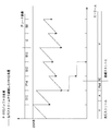
図2は、実施例1における映像符号化部103のVBVバッファ(第1の仮想バッファ)の占有量の遷移を示す概念図である。図2において、実線はシームレス接続を実行する場合の遷移、破線はシームレス接続を実行しない場合の遷移を示す。
FIG. 2 is a conceptual diagram illustrating a change in the occupation amount of the VBV buffer (first virtual buffer) of the
VBVバッファには、転送速度Rmax(第1の速度)で映像ストリームが入力される。本実施例では、映像符号化部103は、MPEG−2規格におけるVBVバッファのモデルに従って、VBVバッファを更新する。即ち、多重化ストリーム中に映像ストリームが含まれるか否かに関わらず(多重化ストリームから取得されるストリームの種類に関わらず)、常に転送速度Rmaxで映像ストリームがVBVバッファに入力され、VBVバッファの占有量が増加する。そして、映像ストリームに含まれるピクチャの復号時刻に、そのピクチャの符号量に相当する量だけ占有量が減少する。
A video stream is input to the VBV buffer at a transfer speed Rmax (first speed). In the present embodiment, the
本実施例では、先行チャプタと後続チャプタとがシームレス接続されるため、先行チャプタの多重化ストリーム(先行ストリーム)と後続チャプタの多重化ストリーム(後続ストリーム)とが一本に繋がっているように扱われる。即ち、多重化部106は、先行する第1の多重化ストリームと後続の第2の多重化ストリームを続けて1つの多重化ストリームとして再生可能なように多重化ストリームを生成する。従って、VBVバッファの占有量は、図2において実線で示すように、多重化ストリーム中に映像ストリームが含まれるか否かに関わらず、転送速度Rmaxで映像ストリームがVBVバッファに入力されるように占有量が遷移する。
In this embodiment, since the preceding chapter and the subsequent chapter are seamlessly connected, the multiplexed stream of the preceding chapter (preceding stream) and the multiplexed stream of the succeeding chapter (following stream) are handled as one. Is called. That is, the
図3は、MPEG−2規格におけるP−STDモデルの構成図である。 FIG. 3 is a configuration diagram of the P-STD model in the MPEG-2 standard.
記録部107が記録媒体(不図示)から多重化ストリームを読み出し、分離部703へ入力する。分離部703は、多重化ストリームをパケット単位に分離してスイッチ301へ入力する。スイッチ301は、パケットのストリームID(パケットの種類)に従ってパケットの出力先を切り換える。例えば、映像ストリームを含むパケットであれば、映像ストリームのP−STDバッファ(第2の仮想バッファ)へ、音声ストリームを含むパケットであれば、音声ストリームのP−STDバッファへと出力先を切り換える。そして、P−STDバッファに格納されたデータは、復号時刻にP−STDバッファから復号化部へと瞬時に転送される。MPEG−2規格では、映像ストリームのP−STDバッファの最大量は238KBと定義されている。
The
図4は、映像ストリームのP−STDバッファの占有量の遷移を示す概念図である。図4を参照して、多重化部106におけるP−STDバッファの占有量の遷移について説明する。
FIG. 4 is a conceptual diagram showing a transition of the occupation amount of the P-STD buffer of the video stream. With reference to FIG. 4, the transition of the occupation amount of the P-STD buffer in the
図3を参照して説明した通り、多重化ストリームの出力先は、パケットの種類に従ってスイッチ301によって切り換えられる。従って、多重化ストリーム中に映像ストリームが存在しない期間は、映像ストリームのP−STDバッファにはデータが入力されない。多重化ストリームのパケットに付加されたタイムスタンプが示すタイミングで、パケット内に含まれる映像ストリームの符号(データ)がP−STDバッファに入力される。まだ多重化されていない時刻の、映像ストリームのP−STDバッファへの入力には、多重化されたストリームのシステムレートから、音声ストリーム、プライベートデータ、各種ヘッダを取り除いた転送レート(RP_STD(第2の速度))を用いる。MPEG−2規格では、RP_STDはRmaxよりも高速(RP_STD>Rmax)である。
As described with reference to FIG. 3, the output destination of the multiplexed stream is switched by the
即ち、P−STDバッファは、多重化ストリームから映像ストリームが取得される期間のみ、占有量が増加する。そして、VBVバッファの場合と同様、映像ストリームに含まれるピクチャの復号時刻に、そのピクチャの符号量に相当する量だけ占有量が減少する。 That is, the occupation amount of the P-STD buffer increases only during the period in which the video stream is acquired from the multiplexed stream. As in the case of the VBV buffer, the occupation amount is reduced by an amount corresponding to the code amount of the picture at the decoding time of the picture included in the video stream.
多重化部106は、図4に示すように映像ストリームのP−STDバッファの占有量を更新し、各復号時刻の占有量を符号化制御部105に通知する。
As illustrated in FIG. 4, the
次に、図5乃至図7を参照して、実施例1においてピクチャに割り当てる符号量の上限値を設定する方法について説明する。 Next, a method for setting the upper limit value of the code amount allocated to the picture in the first embodiment will be described with reference to FIGS.
図5は、従来技術における符号量の設定方法と、実施例1における符号量の設定方法とを比較する図である。 FIG. 5 is a diagram comparing the code amount setting method in the prior art with the code amount setting method in the first embodiment.
図5において一点鎖線で示すように、従来技術によれば、先行ストリームと後続ストリームの境界でVBVバッファの占有量が0にリセットされていた。従って、後続ストリームの先頭ピクチャI2に割り当て可能な符号量の上限値は、
Cmax=(T2−T1)×Rmax
であり、前述の通り、Cmaxは比較的小さな値を取る。
As indicated by the alternate long and short dash line in FIG. 5, according to the prior art, the occupation amount of the VBV buffer was reset to 0 at the boundary between the preceding stream and the succeeding stream. Therefore, the upper limit of the code amount that can be assigned to the first picture I2 of the subsequent stream is
Cmax = (T2-T1) * Rmax
As described above, Cmax takes a relatively small value.
しかし、シームレス接続の実行時には、前述の通り、先行ストリームと後続ストリームとをまとめて一本のストリームとして扱うことができる。そこで、本実施例では、図5において実線で示すように、映像符号化部103はVBVバッファの占有量をリセットせずに後続ストリームを処理する。従って、映像符号化部103は、先頭ピクチャI2に最大でCmax+Δ1の符号量を割り当てることができ、この場合でも、VBVバッファは破綻しない。
However, when the seamless connection is executed, as described above, the preceding stream and the succeeding stream can be collectively handled as one stream. Therefore, in this embodiment, as indicated by a solid line in FIG. 5, the
しかしながら、P−STDバッファには、多重化ストリームに含まれる映像ストリームが入力されるため、先頭ピクチャI2に対応するデータの入力が開始するのは、図5に示す時刻T3である。そのため、先頭ピクチャI2にCmax+Δ1の符号量を割り当てると、VBVバッファは破綻しなくても、P−STDバッファが破綻する可能性がある。 However, since the video stream included in the multiplexed stream is input to the P-STD buffer, the input of data corresponding to the first picture I2 starts at time T3 shown in FIG. Therefore, if the code amount of Cmax + Δ1 is assigned to the leading picture I2, the P-STD buffer may fail even if the VBV buffer does not fail.
そこで、本実施例では、符号化制御部105は、映像データ中の符号化対象のピクチャの復号時刻におけるP−STDバッファの減少前の占有量とVBVバッファの減少前の占有量とを比較する。そして、小さい方の占有量をそのピクチャに割り当てる符号量の上限値として映像符号化部103に設定する。従って、図5の例では、Cmax+Δ2が上限値として設定される。RP_STD>Rmaxであるため、通常、Δ2>0であり、先頭ピクチャI2に割り当て可能な符号量が従来に比べて増加するため、画質の低下が抑制される。また、このように符号量の上限値を設定すれば、P−STDバッファ及びVBVバッファのいずれも破綻しない。
Therefore, in this embodiment, the
また、先頭ピクチャI2のみならず、それ以降のピクチャに対しても同じ方法で符号量の上限値が設定される。従って、後続ストリーム全体について、画質の低下が抑制される。 Further, the upper limit value of the code amount is set not only for the leading picture I2 but also for the subsequent pictures by the same method. Therefore, the deterioration of image quality is suppressed for the entire subsequent stream.
図6は、VBVバッファ占有量の遷移と、映像ストリームのP−STDバッファの占有量の遷移とを示す概念図である。図6において、実線がVBVバッファの遷移を示し、破線はP−STDバッファの遷移を示す。図6に示すように、先行ストリームと後続ストリームとの境界付近では通常、P−STDバッファの占有量の方がVBVバッファ占有量よりも小さい。従って、P−STDバッファの占有量が符号量の上限値として設定される。 FIG. 6 is a conceptual diagram showing a transition of the VBV buffer occupation amount and a transition of the P-STD buffer occupation amount of the video stream. In FIG. 6, the solid line indicates the transition of the VBV buffer, and the broken line indicates the transition of the P-STD buffer. As shown in FIG. 6, generally, the occupation amount of the P-STD buffer is smaller than the occupation amount of the VBV buffer near the boundary between the preceding stream and the succeeding stream. Accordingly, the occupation amount of the P-STD buffer is set as the upper limit value of the code amount.
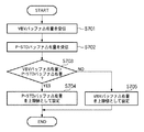
図7は、実施例1において符号化制御部105が実行する、符号量の上限値を設定する処理の流れを示すフローチャートである。本フローチャートの処理は、映像符号化部103による符号化対象の各ピクチャに対して実行される。
FIG. 7 is a flowchart illustrating a flow of processing for setting the upper limit value of the code amount, which is executed by the
S701で、符号化制御部105は、VBVバッファの占有量を映像符号化部103から受信する。
In step S <b> 701, the
S702で、符号化制御部105は、P−STDバッファの占有量を多重化部106から受信する。
In step S <b> 702, the
S703で、符号化制御部105は、(VBVバッファの占有量)>(P−STDバッファの占有量)であるか否かを判定する。(VBVバッファの占有量)>(P−STDバッファの占有量)であればS704に進み、そうでなければS705に進む。
In step S703, the
S704では、符号化制御部105は、P−STDバッファの占有量を符号化対象のピクチャの符号量の上限値として映像符号化部103に設定する。
In S704, the
S705では、符号化制御部105は、VBVバッファの占有量を符号化対象のピクチャの符号量の上限値として映像符号化部103に設定する。
In S705, the
以上の処理により、符号化対象のピクチャの符号量の上限値は、図8に示すように遷移する。 By the above processing, the upper limit value of the code amount of the picture to be encoded is changed as shown in FIG.
なお、符号化制御部105は、後続ストリームの符号化の開始後、(VBVバッファの占有量)>(P−STDバッファの占有量)であると判定されると、これ以降はS703における比較を停止してもよい。比較の停止中は、符号化制御部105は、VBVバッファの占有量を符号化対象のピクチャの符号量の上限値として映像符号化部103に設定する。これにより、符号化制御部105の処理負荷が低減される。
If it is determined that (VBV buffer occupancy)> (P-STD buffer occupancy) after the start of encoding of the subsequent stream, the
以上説明したように、本実施例によれば、ビデオカメラ100は、符号化対象のピクチャの復号時刻におけるVBVバッファの占有量とP−STDバッファの占有量とを比較する。そして、小さい方の値を符号量の上限値として設定する。 As described above, according to this embodiment, the video camera 100 compares the occupation amount of the VBV buffer and the occupation amount of the P-STD buffer at the decoding time of the picture to be encoded. The smaller value is set as the upper limit of the code amount.
これにより、後続チャプタを先行チャプタにシームレス接続させる際に、後続チャプタの画質の劣化を抑制することが可能となる。 Thus, when the subsequent chapter is seamlessly connected to the preceding chapter, it is possible to suppress deterioration of the image quality of the subsequent chapter.
なお、本実施形態では、映像データと音声データをMPEG2方式で符号化して記録する構成について説明した。 In the present embodiment, the configuration in which video data and audio data are encoded and recorded by the MPEG2 system has been described.
これ以外にも、例えば、H.264/MPEG4−AVC方式など、仮想バッファを使って符号量制御を行う他の符号化方式を使った場合においても、本発明を同様に適用可能である。 Other than this, for example, H.P. The present invention is also applicable to the case of using another encoding method that performs code amount control using a virtual buffer, such as the H.264 / MPEG4-AVC method.
[その他の実施例]
上述した各実施例の機能を実現するためには、各機能を具現化したソフトウェアのプログラムコードを記録した記録媒体をシステム或は装置に提供してもよい。そして、そのシステム或は装置のコンピュータ(又はCPUやMPU)が記録媒体に格納されたプログラムコードを読み出し実行することによって、上述した各実施例の機能が実現される。この場合、記録媒体から読み出されたプログラムコード自体が上述した各実施例の機能を実現することになり、そのプログラムコードを記録した記録媒体は本発明を構成することになる。このようなプログラムコードを供給するための記録媒体としては、例えば、フロッピィ(登録商標)ディスク、ハードディスク、光ディスク、光磁気ディスクなどを用いることができる。或いは、CD−ROM、CD−R、磁気テープ、不揮発性のメモリカード、ROMなどを用いることもできる。
[Other Examples]
In order to realize the functions of the above-described embodiments, a recording medium in which a program code of software embodying each function is recorded may be provided to the system or apparatus. Then, the function of each embodiment described above is realized by the computer (or CPU or MPU) of the system or apparatus reading and executing the program code stored in the recording medium. In this case, the program code itself read from the recording medium realizes the functions of the above-described embodiments, and the recording medium on which the program code is recorded constitutes the present invention. As a recording medium for supplying such a program code, for example, a floppy (registered trademark) disk, a hard disk, an optical disk, a magneto-optical disk, or the like can be used. Alternatively, a CD-ROM, CD-R, magnetic tape, nonvolatile memory card, ROM, or the like can be used.
また、上述した各実施例の機能を実現するための構成は、コンピュータが読み出したプログラムコードを実行することだけには限られない。そのプログラムコードの指示に基づき、コンピュータ上で稼動しているOS(オペレーティングシステム)などが実際の処理の一部又は全部を行い、その処理によって上述した各実施例の機能が実現される場合も含まれている。 The configuration for realizing the functions of the above-described embodiments is not limited to executing the program code read by the computer. Including the case where the OS (operating system) running on the computer performs part or all of the actual processing based on the instruction of the program code, and the functions of the above-described embodiments are realized by the processing. It is.
さらに、記録媒体から読み出されたプログラムコードが、コンピュータに挿入された機能拡張ボードやコンピュータに接続された機能拡張ユニットに備わるメモリに書きこまれてもよい。その後、そのプログラムコードの指示に基づき、その機能拡張ボードや機能拡張ユニットに備わるCPUなどが実際の処理の一部又は全部を行い、その処理によって上述した各実施例の機能が実現される場合も含むものである。 Further, the program code read from the recording medium may be written in a memory provided in a function expansion board inserted into the computer or a function expansion unit connected to the computer. Thereafter, the CPU of the function expansion board or function expansion unit performs part or all of the actual processing based on the instruction of the program code, and the functions of the above-described embodiments may be realized by the processing. Is included.
Claims (6)
音声データを符号化し、音声ストリームを生成する音声符号化部と、
前記映像ストリームと前記音声ストリームとを多重化して多重化ストリームを生成する多重化部であって、先行する第1の多重化ストリームと後続の第2の多重化ストリームとを続けて1つの連続した多重化ストリームとして再生可能なように前記多重化ストリームを生成する多重化部と、
前記多重化ストリームを記録媒体に記録する記録部と、
前記第1の多重化ストリームの末尾のピクチャと前記第2の多重化ストリームの先頭ピクチャとの間の期間も含めて前記多重化ストリームから取得されるストリームの種類に関わらず第1の速度で占有量が増加し、前記映像ストリームに含まれるピクチャの復号時刻に当該ピクチャの符号量に相当する量だけ占有量が減少する第1の仮想バッファと、
前記多重化ストリームから前記映像ストリームが取得される期間のみ、前記第1の速度よりも高速な第2の速度で占有量が増加し、前記映像ストリームに含まれるピクチャの復号時刻に当該ピクチャの符号量に相当する量だけ占有量が減少する第2の仮想バッファと、
前記映像データ中の符号化対象のピクチャの復号時刻における、前記第1の仮想バッファの減少前の占有量と前記第2の仮想バッファの減少前の占有量とを比較し、小さい方の占有量を当該符号化対象のピクチャに割り当てる符号量の上限値として前記映像符号化部に設定する制御部と、
を備えることを特徴とする記録装置。 A video encoding unit that encodes video data and generates a video stream;
An audio encoding unit that encodes audio data and generates an audio stream;
A multiplexing unit that multiplexes the video stream and the audio stream to generate a multiplexed stream, wherein the preceding first multiplexed stream and the succeeding second multiplexed stream are continued one by one A multiplexing unit for generating the multiplexed stream so as to be reproducible as a multiplexed stream;
A recording unit for recording the multiplexed stream on a recording medium;
Occupied at the first rate regardless of the type of stream acquired from the multiplexed stream including the period between the last picture of the first multiplexed stream and the first picture of the second multiplexed stream A first virtual buffer in which the amount increases and the occupation amount decreases by an amount corresponding to the code amount of the picture at the decoding time of the picture included in the video stream;
Only during the period when the video stream is acquired from the multiplexed stream, the occupation amount increases at a second speed higher than the first speed, and the code of the picture is decoded at the decoding time of the picture included in the video stream. A second virtual buffer whose occupancy decreases by an amount corresponding to the amount;
Compare the occupancy before the decrease of the first virtual buffer with the occupancy before the decrease of the second virtual buffer at the decoding time of the picture to be encoded in the video data, and the smaller occupancy A control unit that sets the upper limit of the code amount to be assigned to the picture to be encoded in the video encoding unit;
A recording apparatus comprising:
前記第2の仮想バッファはMPEG規格のP−STDバッファである
ことを特徴とする請求項1又は2に記載の記録装置。 The first virtual buffer is an MPEG standard VBV buffer;
The recording apparatus according to claim 1, wherein the second virtual buffer is an MPEG standard P-STD buffer.
音声データを符号化し、音声ストリームを生成する音声符号化部と、
前記映像ストリームと前記音声ストリームとを多重化して多重化ストリームを生成する多重化部であって、先行する第1の多重化ストリームと後続の第2の多重化ストリームとを続けて1つの連続した多重化ストリームとして再生可能なように前記多重化ストリームを生成する多重化部と、
前記多重化ストリームを記録媒体に記録する記録部と、
前記第1の多重化ストリームの末尾のピクチャと前記第2の多重化ストリームの先頭ピクチャとの間の期間も含めて前記多重化ストリームから取得されるストリームの種類に関わらず第1の速度で占有量が増加し、前記映像ストリームに含まれるピクチャの復号時刻に当該ピクチャの符号量に相当する量だけ占有量が減少する第1の仮想バッファと、
前記多重化ストリームから前記映像ストリームが取得される期間のみ、前記第1の速度よりも高速な第2の速度で占有量が増加し、前記映像ストリームに含まれるピクチャの復号時刻に当該ピクチャの符号量に相当する量だけ占有量が減少する第2の仮想バッファと、
を備える記録装置の制御方法であって、
前記記録装置の制御手段が、前記映像データ中の符号化対象のピクチャの復号時刻における、前記第1の仮想バッファの減少前の占有量と前記第2の仮想バッファの減少前の占有量とを比較し、小さい方の占有量を当該符号化対象のピクチャに割り当てる符号量の上限値として前記映像符号化部に設定する制御工程
を備えることを特徴とする制御方法。 A video encoding unit that encodes video data and generates a video stream;
An audio encoding unit that encodes audio data and generates an audio stream;
A multiplexing unit that multiplexes the video stream and the audio stream to generate a multiplexed stream, wherein the preceding first multiplexed stream and the succeeding second multiplexed stream are continued one by one A multiplexing unit for generating the multiplexed stream so as to be reproducible as a multiplexed stream;
A recording unit for recording the multiplexed stream on a recording medium;
Occupied at the first rate regardless of the type of stream acquired from the multiplexed stream including the period between the last picture of the first multiplexed stream and the first picture of the second multiplexed stream A first virtual buffer in which the amount increases and the occupation amount decreases by an amount corresponding to the code amount of the picture at the decoding time of the picture included in the video stream;
Only during the period when the video stream is acquired from the multiplexed stream, the occupation amount increases at a second speed higher than the first speed, and the code of the picture is decoded at the decoding time of the picture included in the video stream. A second virtual buffer whose occupancy decreases by an amount corresponding to the amount;
A control method for a recording apparatus comprising:
The control means of the recording apparatus determines the occupation amount before the decrease of the first virtual buffer and the occupation amount before the decrease of the second virtual buffer at the decoding time of the picture to be encoded in the video data. A control method comprising: a control step of comparing and setting the smaller occupancy amount in the video encoding unit as an upper limit value of a code amount to be assigned to the picture to be encoded.
音声データを符号化し、音声ストリームを生成する音声符号化部と、
前記映像ストリームと前記音声ストリームとを多重化して多重化ストリームを生成する多重化部であって、先行する第1の多重化ストリームと後続の第2の多重化ストリームとを続けて1つの連続した多重化ストリームとして再生可能なように前記多重化ストリームを生成する多重化部と、
前記多重化ストリームを記録媒体に記録する記録部と、
前記第1の多重化ストリームの末尾のピクチャと前記第2の多重化ストリームの先頭ピクチャとの間の期間も含めて前記多重化ストリームから取得されるストリームの種類に関わらず第1の速度で占有量が増加し、前記映像ストリームに含まれるピクチャの復号時刻に当該ピクチャの符号量に相当する量だけ占有量が減少する第1の仮想バッファと、
前記多重化ストリームから前記映像ストリームが取得される期間のみ、前記第1の速度よりも高速な第2の速度で占有量が増加し、前記映像ストリームに含まれるピクチャの復号時刻に当該ピクチャの符号量に相当する量だけ占有量が減少する第2の仮想バッファと、
を備える記録装置のコンピュータに、
前記映像データ中の符号化対象のピクチャの復号時刻における、前記第1の仮想バッファの減少前の占有量と前記第2の仮想バッファの減少前の占有量とを比較し、小さい方の占有量を当該符号化対象のピクチャに割り当てる符号量の上限値として前記映像符号化部に設定する制御工程
を実行させるためのプログラム。 A video encoding unit that encodes video data and generates a video stream;
An audio encoding unit that encodes audio data and generates an audio stream;
A multiplexing unit that multiplexes the video stream and the audio stream to generate a multiplexed stream, wherein the preceding first multiplexed stream and the succeeding second multiplexed stream are continued one by one A multiplexing unit for generating the multiplexed stream so as to be reproducible as a multiplexed stream;
A recording unit for recording the multiplexed stream on a recording medium;
Occupied at the first rate regardless of the type of stream acquired from the multiplexed stream including the period between the last picture of the first multiplexed stream and the first picture of the second multiplexed stream A first virtual buffer in which the amount increases and the occupation amount decreases by an amount corresponding to the code amount of the picture at the decoding time of the picture included in the video stream;
Only during the period when the video stream is acquired from the multiplexed stream, the occupation amount increases at a second speed higher than the first speed, and the code of the picture is decoded at the decoding time of the picture included in the video stream. A second virtual buffer whose occupancy decreases by an amount corresponding to the amount;
In a computer of a recording device comprising
Compare the occupancy before the decrease of the first virtual buffer with the occupancy before the decrease of the second virtual buffer at the decoding time of the picture to be encoded in the video data, and the smaller occupancy For executing the control step of setting the video encoding unit as the upper limit value of the code amount to be assigned to the picture to be encoded.
Priority Applications (1)
| Application Number | Priority Date | Filing Date | Title |
|---|---|---|---|
| JP2007325209A JP5046907B2 (en) | 2007-12-17 | 2007-12-17 | Recording apparatus, control method therefor, and program |
Applications Claiming Priority (1)
| Application Number | Priority Date | Filing Date | Title |
|---|---|---|---|
| JP2007325209A JP5046907B2 (en) | 2007-12-17 | 2007-12-17 | Recording apparatus, control method therefor, and program |
Publications (3)
| Publication Number | Publication Date |
|---|---|
| JP2009147827A JP2009147827A (en) | 2009-07-02 |
| JP2009147827A5 JP2009147827A5 (en) | 2011-01-27 |
| JP5046907B2 true JP5046907B2 (en) | 2012-10-10 |
Family
ID=40917880
Family Applications (1)
| Application Number | Title | Priority Date | Filing Date |
|---|---|---|---|
| JP2007325209A Expired - Fee Related JP5046907B2 (en) | 2007-12-17 | 2007-12-17 | Recording apparatus, control method therefor, and program |
Country Status (1)
| Country | Link |
|---|---|
| JP (1) | JP5046907B2 (en) |
Families Citing this family (3)
| Publication number | Priority date | Publication date | Assignee | Title |
|---|---|---|---|---|
| JP5685075B2 (en) * | 2010-12-24 | 2015-03-18 | キヤノン株式会社 | Recording apparatus, recording method, and program |
| JP2012244542A (en) * | 2011-05-23 | 2012-12-10 | Sony Corp | Coding device, coding method, and program |
| JP5947641B2 (en) * | 2012-07-06 | 2016-07-06 | キヤノン株式会社 | Moving picture coding apparatus, control method therefor, and computer program |
Family Cites Families (2)
| Publication number | Priority date | Publication date | Assignee | Title |
|---|---|---|---|---|
| JP3403865B2 (en) * | 1995-06-08 | 2003-05-06 | 株式会社東芝 | Stream multiplexing apparatus and stream multiplexing method |
| JP3675464B2 (en) * | 2003-10-29 | 2005-07-27 | ソニー株式会社 | Moving picture coding apparatus and moving picture coding control method |
-
2007
- 2007-12-17 JP JP2007325209A patent/JP5046907B2/en not_active Expired - Fee Related
Also Published As
| Publication number | Publication date |
|---|---|
| JP2009147827A (en) | 2009-07-02 |
Similar Documents
| Publication | Publication Date | Title |
|---|---|---|
| JP2003046949A (en) | Data multiplexing method, data recording medium, data recording apparatus, and data recording program | |
| JP5947641B2 (en) | Moving picture coding apparatus, control method therefor, and computer program | |
| JPH1188874A (en) | Method for inserting editable point in encoding device and the encoding device | |
| JP4788250B2 (en) | Moving picture signal encoding apparatus, moving picture signal encoding method, and computer-readable recording medium | |
| JP5046907B2 (en) | Recording apparatus, control method therefor, and program | |
| US8190000B2 (en) | Recording apparatus, recording method, and recording program | |
| JP3951839B2 (en) | Image data reproducing apparatus and method | |
| JP2007158432A (en) | Video recording device | |
| JP2006066995A (en) | Image reproducer, its control method and program, and storage medium | |
| JP2002010254A (en) | Feature point detection method and record reproduction device | |
| JP4900945B2 (en) | Recording apparatus and recording method | |
| JP2003324690A (en) | Video record playback device | |
| JP2007259493A (en) | Encoding device and encoding method | |
| KR20040010173A (en) | Image data reproducing device and method | |
| JP3443391B2 (en) | Digital decoding method | |
| JP2004248199A (en) | System multiplexing apparatus | |
| JP4867872B2 (en) | Image processing apparatus, control method for the image processing apparatus, and program | |
| JP2004048103A (en) | Image data processing apparatus and method | |
| JP3897783B2 (en) | Image processing apparatus, control method therefor, computer program, and computer-readable storage medium | |
| EP1067793A2 (en) | Digital video decoding method | |
| JP2004180282A (en) | Stream information reproducing apparatus, stream information reproducing method, program, and digital broadcasting receiver | |
| JP4788251B2 (en) | Video signal encoding apparatus | |
| JPH11220695A (en) | Device and method for decoding moving image data | |
| JP4835651B2 (en) | Multiplexing control apparatus and multiplexing control method | |
| JP2008136001A (en) | Encoding method conversion device |
Legal Events
| Date | Code | Title | Description |
|---|---|---|---|
| A521 | Written amendment |
Free format text: JAPANESE INTERMEDIATE CODE: A523 Effective date: 20101129 |
|
| A621 | Written request for application examination |
Free format text: JAPANESE INTERMEDIATE CODE: A621 Effective date: 20101129 |
|
| A977 | Report on retrieval |
Free format text: JAPANESE INTERMEDIATE CODE: A971007 Effective date: 20110906 |
|
| A131 | Notification of reasons for refusal |
Free format text: JAPANESE INTERMEDIATE CODE: A131 Effective date: 20110930 |
|
| A521 | Written amendment |
Free format text: JAPANESE INTERMEDIATE CODE: A523 Effective date: 20111125 |
|
| TRDD | Decision of grant or rejection written | ||
| A01 | Written decision to grant a patent or to grant a registration (utility model) |
Free format text: JAPANESE INTERMEDIATE CODE: A01 Effective date: 20120615 |
|
| A01 | Written decision to grant a patent or to grant a registration (utility model) |
Free format text: JAPANESE INTERMEDIATE CODE: A01 |
|
| A61 | First payment of annual fees (during grant procedure) |
Free format text: JAPANESE INTERMEDIATE CODE: A61 Effective date: 20120717 |
|
| FPAY | Renewal fee payment (event date is renewal date of database) |
Free format text: PAYMENT UNTIL: 20150727 Year of fee payment: 3 |
|
| LAPS | Cancellation because of no payment of annual fees |