EP1067722A2 - Mapping arbitrary signals into sonet - Google Patents
Mapping arbitrary signals into sonet Download PDFInfo
- Publication number
- EP1067722A2 EP1067722A2 EP00305782A EP00305782A EP1067722A2 EP 1067722 A2 EP1067722 A2 EP 1067722A2 EP 00305782 A EP00305782 A EP 00305782A EP 00305782 A EP00305782 A EP 00305782A EP 1067722 A2 EP1067722 A2 EP 1067722A2
- Authority
- EP
- European Patent Office
- Prior art keywords
- data
- stuff
- bits
- rate
- frame
- Prior art date
- Legal status (The legal status is an assumption and is not a legal conclusion. Google has not performed a legal analysis and makes no representation as to the accuracy of the status listed.)
- Granted
Links
Images

Classifications
-
- H—ELECTRICITY
- H04—ELECTRIC COMMUNICATION TECHNIQUE
- H04J—MULTIPLEX COMMUNICATION
- H04J3/00—Time-division multiplex systems
- H04J3/16—Time-division multiplex systems in which the time allocation to individual channels within a transmission cycle is variable, e.g. to accommodate varying complexity of signals, to vary number of channels transmitted
- H04J3/1605—Fixed allocated frame structures
- H04J3/1623—Plesiochronous digital hierarchy [PDH]
- H04J3/1629—Format building algorithm
-
- H—ELECTRICITY
- H04—ELECTRIC COMMUNICATION TECHNIQUE
- H04J—MULTIPLEX COMMUNICATION
- H04J3/00—Time-division multiplex systems
- H04J3/16—Time-division multiplex systems in which the time allocation to individual channels within a transmission cycle is variable, e.g. to accommodate varying complexity of signals, to vary number of channels transmitted
- H04J3/1605—Fixed allocated frame structures
- H04J3/1611—Synchronous digital hierarchy [SDH] or SONET
Definitions
- the invention is directed to transparent transportation of data signals with a continuous format, and in particular to a method for mapping arbitrary continuous signals into a SONET frame.
- Rapid provisioning of a customer's requested service is a valuable network function.
- Data transmission formats can be divided into SONET, other continuous formats, and burst formats. Burst formats do not have a continuous clock, transmission of such signals do not require any given phase relationship between bursts. On the other hand, the phase of the clock of continuous formats has continuity under normal conditions, and the frequency of the clock is bounded. Examples of such bounds are ⁇ 20ppm (parts per million of the bit rate) and ⁇ 100 ppm.
- SONET The dominant signal format in the fiber optic networks follows the synchronous standard SONET in North America and SDH elsewhere.
- SONET is defined to include SDH.
- SONET enables multiplexing, adding and dropping, and general transportation of signals.
- being able to be easily transported by a SONET network is a valuable attribute, in that it enables the network providers to make use of the large base of installed SONET-compatible equipment.
- SONET is a physical carrier technology, which can provide a transport service for ATM, SMDS, frame relay, T1, E1, etc.
- OAM&P operation, administration, maintenance and provisioning
- Opto/electrical conversion takes place at the periphery of the SONET network, where the optical signals are converted into a standard electrical format called the synchronous transport signal (STS), which is the equivalent of the optical signal.
- STS synchronous transport signal
- the STS signals are carried by a respective optical carrier, which is defined according to the STS that it carries.
- an STS-192 signal is carried by an OC-192 optical signal.
- the STS-1 frame consists of 90 columns by 9 rows of bytes, the frame length is 125 microseconds.
- a frame comprises a transport overhead (TOH) occupying 3 columns by 9 rows of bytes, and a synchronous payload envelope (SPE) occupying 87 columns of 9 rows of bytes.
- TOH transport overhead
- SPE synchronous payload envelope
- the first column of the SPE is occupied by path overhead bytes.
- an STS-1 has a bit rate of 51.840 Mb/s.
- Lower rates are subsets of STS-1 and are known as virtual tributaries (VT), which may transport rates below DS3.
- VT virtual tributaries
- An STS-N signal is obtained by interleaving N STS-1 signals.
- an STS-192 is made of 192 STS-1 tributaries, each separately visible, and separately aligned within the envelope. The individual tributaries could carry a different payload, each with a different destination.
- the STS-N has a TOH made of all N TOHs of the individual tributaries, and a SPE made of all N SPEs of the tributaries, each with its own POH.
- Some services, that operate at a higher rate, are transmitted in an STS-Nc signal (c for concatenation).
- the STS-1s into the STS-Nc signal are kept together.
- the whole envelope of the STS-Nc signal is routed, multiplexed and transported as a single entity rather than as N individual entities.
- the TOH and the start of the SPE for the N constituents are all aligned, since all the constituents are generated by the same source, with the same clock.
- the first STS-1 in the concatenated signal carries the single set of POH, all that is required for an STS-Nc.
- mappings cannot be used to map rates that vary significantly from the standard.
- mappings are each precisely tuned for a particular format and a particular bit-rate, with e.g. a ⁇ 20ppm tolerance. If a signal has, for example, a bit rate even 1% different than that of a DS3, cannot be transported within SONET.
- a different hardware unit is generally required to perform the mapping of each kind of signal.
- a solution to the above problem is to add a "wrapper" to an arbitrary continuous signal.
- the rate of the resulting signal is a function of the signal being wrapped. Namely, a 1 Mb/s wrapper added to a signal of rate X produces a format with rate X+1 Mb/s. A variation on this adds a percentage of X. For example, a common line coding 8B/10B produces a format with a rate of 112.5% of X.
- the "wrapper" methods do not produce formats that have a pre-defined fixed bit rate for arbitrary inputs.
- the resulting signal cannot in general be time multiplexed to be transported on a high speed network.
- Packet or cell based formats map arbitrary input streams into SONET and SDH. While adequate for packet systems, these methods do not meet the jitter or wander requirements of most continuous signal formats due to the "one size fits all" mapping methods used. The clock phase information of the input signal is effectively eliminated in these methods, and so cannot be transmitted.
- US Patent Application 09/307812 (Solheim et al., entitled “Protocol Independent sub-rate device” filed on May 10, 1999 and assigned to Nortel Networks Corporation) discloses a method of transporting different type of clients (IP, ATM, SONET, Ethernet, etc.) together.
- the '812 application discloses time-multiplexing lower speed (subrate) channels of arbitrary rates and formats into a single higher speed channel, and then demultipexing the channels at the far end of the system.
- the portion of the bandwidth assigned to any given subrate channel can be provisioned without any change to the hardware or software. This significantly simplifies and speeds the provisioning of these services by the carrier. Tributaries with new protocols can be accommodated as well, significantly speeding up the delivery of support for these new protocols.
- the invention comprises a method for transmitting a continuous digital signal of an arbitrary rate R1 over a synchronous network as a transparent tributary, selecting a fixed length container signal of a rate R, where R is higher than the arbitrary rate R1 of the continuous signal, and at a transmit site, distributing the bits of the continuous signal into valid timeslots of a frame of the container signal and providing stuff bits into invalid timeslots, wherein the invalid timeslots are uniformly interspersed across the frame.
- the method of the present invention maps arbitrary signals having a continuous format into a SONET frame. This allows any qualified format to be transparently transported within a SONET network.
- the invention further comprises a synchronizer for mapping a continuous format signal of an arbitrary rate for transport over a synchronous network as a transparent tributary signal, comprising a data recovery unit for receiving the continuous format signal and recovering a stream of data bits and a data clock indicative of the arbitrary rate, a receiver buffer unit for receiving the stream of data bits, determining a phase difference between the arbitrary rate and the rate of a frame of the tributary, and generating a control function ⁇ , a mapping unit for extracting the stream of data bits from the receiver buffer unit at a mapping clock rate, and uniformly distributing a count of stuff bits and data bits into the frame at a block clock rate according to the control function ⁇ .
- a synchronizer for mapping a continuous format signal of an arbitrary rate for transport over a synchronous network as a transparent tributary signal, comprising a data recovery unit for receiving the continuous format signal and recovering a stream of data bits and a data clock indicative of the arbitrary rate, a receiver buffer unit for receiving the stream
- a de-synchronizer for reverse mapping a continuous format signal of an arbitrary rate received over a synchronous network as a transparent tributary signal comprising, a reverse mapping unit for receiving a frame of the tributary at a block clock rate and a control function ⁇ , and extracting a stream of data bits at a mapping clock rate, while excluding stuff bits according to the control function ⁇ , a transmitter buffer unit for receiving the data bits, and determining a phase difference between the arbitrary rate and the rate of the frame, and a data transmit unit for receiving the data bits and transmitting the continuous format signal at a data rate controlled by the phase difference.
- the method of mapping according to the invention allows use of a common technology, such as SONET, for transparently transporting tributaries of same or different formats. Almost any continuous format could be transported by SONET using this novel mapping, without changing any bit.
- Another advantage of the present invention is that the jitter or wander added by the method is minimal.
- the synchronized/desynchronizer handles signals whose format is unknown at the time of design, as long as the jitter tolerance and generation specifications are compatible with the very accommodating range designed into the unit. This is a proprietary mapping, that is designed on the fly by the trib software, and is communicated within the channel to the corresponding trib at the far end.
- the mapping system maps a digital signal that has a constant line rate, up to the designated maximum capacity, into a SONET envelope of a provisioned size.
- a mapping function could be performed in a tributary unit of a SONET transport shelf, and the reverse mapping function (also called de-mapping) could be performed in a similar unit at the far end of a SONET connection.
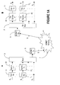
- Figure 1A shows a block diagram of an exemplary transmission system with the mapping system according to the invention, transparently transporting a plurality of services over a SONET network. Only one direction of transmission, as shown by the arrows, is illustrated on this figure for simplification.
- Signals S 1 ,... S j ,... S n are carried between two sites A and B into a SONET signal S, over a SONET network 7 .
- Signals S 1 - S n are digital signals of a continuous format, and are treated at the nodes A and B as tributaries of SONET signal S.
- Signals S j can carry the same or different type of services.
- Each trib receiver 1 - 1 n recovers the data bits for the respective continuous format signal S 1 - S n .
- Node A is provided with one or more synchronizers 20 1 - 20 n , each synchronizer 20 j for mapping the data bits of corresponding trib signal S j into a SONET envelope of an appropriate size.
- the size of the frame to carry transparently the continuous signals between certain transmission nodes is selected in software, and is provisioned having in view a satisfactory bandwidth usage for a large range of continuous format signals. For example, if a nxSTS-12 is used for the envelope, n is between four and twenty for a high speed variant of the synchronizer, and between one and five for a medium speed variant. This avoids stranding significant network capacity.
- the tributaries are multiplexed by a SONET multiplexer 3 into a high rate signal S , which is launched by a SONET transmitter 5 over optical network 7 towards site B .
- the reverse operation is performed at site B .
- the optical receiver 9 recovers the data in signal S
- demultiplexer 3' separates the signals and presents them to a respective de-synchronizer 40 - 40 n .
- Each de-synchronizer 40 j re-arranges the bits in the respective format associated with the signal S j , which is presented to a trib transmitter 11 j .
- Each trib transmitter 11-11 n launches the respective signal S 1 - S n on the associated trib network, or to an associated end user.
- An example of a mapping algorithm is provided next for an STS-192c signal, for showing the basic concepts and the feasibility.
- Other envelopes can also be used, the invention not being limited to the STS-192c signals.
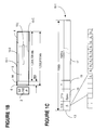
- Figure 1B shows an STS-192c frame 1 , comprising TOH 2, and the STS-192c SPE (synchronous payload envelope) 4 .
- a block 10-j is defined herein as a 1056-bit field, which comprises data bits, fixed stuff bits and adaptive stuff bits, as it will be seen later.
- Block field 8 has 1,201,728 bits.
- the number of the bits in fields 6 and 14 is unchanged, irrespective of the rate R1 of the continuous format signal mapped into the SONET frame 1 . Therefore, these bits are called in the following fixed stuff bits.
- the number of stuff bits necessary to fill the block field 8 varies function of the rate R1 of the continuous format signal S1 .
- These stuff bits are called herein adaptive stuff bits.
- the data bits of the signal S1 are mapped into frame 1 with evenly interspersed fixed stuff bits and adaptive stuff bits. These stuff bits are distributed uniformly within each block, on the fly, since the rate R1 may not be known in advance. Therefore, the synchronizer defines a valid location, that is a location for a data bit, and an invalid location, that is a location for a stuff bit for the next block, based on phase information accumulated when the data bits of the current block are mapped. In addition, the synchronizer also distributes evenly the overhead bits at the time of the actual mapping, but realigns these in the timeslots provided according to the SONET standard after mapping operation, so that the frame is recognized by the SONET equipment. At the far end, the synchronizer effects the reverse operation, by absorbing the fixed stuff bits and the adaptive stuff bits, so that the data bits can be reverse-mapped to regenerate S1 .
- Figure 1B shows the structure of a frame intuitively; in accordance with this invention the mapping algorithm distributes the fixed stuff bits and the adaptive stuff bits uniformly within the frame 1 .
- the above calculations are applicable to a STS-192c frame; similar consideration apply to other SONET signals.
- a block 10-1 comprises a data field 17 having 1023 (2 10 -1) bits for data, a control field 13 having 16 bits, and a spare field 15 having 17 bits for future use.
- the 1023 bits of field 17 provide a bit rate of 9,313.392 Mbps (1023 x 1138 x 8000) for transportation of the data into a STS-192c frame.
- the size of the frame is provisioned and fixed for a certain application, i.e. tributaries of arbitrary rates are mapped in frames of a same size.
- the mapping technique is adaptive for any trib, rather than a different frame being used for every trib. If a trib has a lower rate than 9,313,392 Mbps, it must be justified into the STS-192c, changing more of the bits of data field 8 into stuff bits.
- Figure 1C illustrates field 19 within field 17 , of a variable size v, which size is determined during mapping by comparing the phase between the clock of signals S1 to that of signal S .
- Field 13 comprises a 10-bit control function ⁇ .
- the size of ⁇ was selected in accordance with the size of the block, so as to uniquely determine the position of valid bits in the next block, according to the adaptive stuffing algorithm below.
- a 10-bit number can assume 1024 values, which is one more than the size of a block.
- the value of ⁇ also gives the number of the valid bits in the next block.
- the additional 6 bits of field 13 are necessary for single bit error correction and multiple error detection.
- the ⁇ from the previous block is used as the default, for fast reframing downstream with a minimal PLL transient.
- the bits of fields 15 and 19 are interspersed within the block.
- the value of ⁇ may change between adjacent blocks, as not all blocks have the same number of adaptive stuff bits, but ⁇ remains constant within each block.
- the adaptive stuffing algorithm defines the binary bit reversal of ⁇ which is denoted with ⁇ . That is, the most significant bit of ⁇ becomes the least significant bit of ⁇ ; similarly the least significant bit of ⁇ becomes the most significant bit of ⁇ . Table 1 details this translation by way of examples.
- ⁇ is also determined on a per block basis, and as in the case of ⁇ , the value of ⁇ may change between the adjacent blocks but does not change within a block.
- C is the counter of bits in a block, and is represented by a 10 bits binary number. C increments from 1 to 1023, and as such identifies the timeslot occupied by a bit in the block.
- D is the bit-wise transition delta of C , and is represented by a 10 bit binary number with exactly one bit set. This set bit is in the position of a 0 - to - 1 transition that occurs when counter C advances with one bit.
- Table 2 gives examples of the values assumed by D for a given value of C .
- Determination of D for a given C C 1,2...n Counter of bits in the block D1,2...n Bit-wise transition ⁇ of C C 1 C 2 C 3 C 4 C 5 C 6 C 7 C 8 C 9 C 10 D 1 D 2 D 3 D 4 D 5 D 6 D7 D 8 D 9 D 10 C-1 1 0 0 0 0 0 0 0 0 0 0 1 0 0 0 0 0 0 0 0 0 0 C 1 0 0 0 0 0 0 0 0 0 0 0 0 1 0 0 0 0 0 0 0 0 0 0 1 C+ 1 1 0 0 0 0 0 0 0 0 0 0 0 0 0 0 1 0 C+ 2 1 0 0 0 0 0 0 0 0 0 0 0 0 0 0
- the adaptive stuffing algorithm states that a bit is valid when a bit in D is also set in ⁇ .
- a valid bit corresponds to a bit which is assigned to data, and consequently an invalid bit corresponds to a stuff bit.
- Table 3 shows a simple example of how the algorithm works for a block with 7 bits, for which size of ⁇ is 3 bits. It is to be understood that the algorithm operates in a similar way for blocks of 1023 bits and a 10-bit ⁇ , but it is impractical to detail the full stuffing sequences in this specification.
- Table 3 The entries in Table 3 are the result of the binary function Valid(C, ⁇ ).
- the columns illustrate how data and stuff bits are interspersed for a particular number of valid bits in the block, as given by ⁇ .
- counter C counts from 1 to 7 and D is evaluated in the respective column, for all values of C .
- Each value of D, as C increments, is then compared with ⁇ . If the set bit in D is also set in ⁇ , the corresponding C th bit in the block will be a data bit. If the set bit in D is not set in ⁇ , the corresponding C th bit in the block will be a stuff bit.
- Table 4 details the stuffing sequence for 5 consecutive blocks, with a slightly different between blocks.
- counter C counts from 1 to 7, and two consecutive blocks are shown with a different background (grey and white) for clarity.
- Adaptive Stuff algorithm for five consecutive 7-bit blocks ⁇ 000 001 010 011 100 101 110 111 ⁇ 000 100 010 110 001 101 011 111 C D Valid(C,0) Valid(C,1) Valid(C,2) Valid(C,3) Valid(C,4) Valid(C,5) Valid(C,6) Valid(C,7) 1 001 001 Stuff Stuff Stuff Stuff Stuff Data Data Data Data Data 2 010 010 Stuff Stuff Data Data Stuff Stuff Data Data Data 3 011 001 Stuff Stuff Stuff Stuff Data Data Data Data Data Data Data 4 100 100 Stuff Data Stuff Data Stuff Data Stuff Data 5 101 001 Stuff Stuff Stuff Data Data Data Data Data Data Data Data Data 6 110 010 Stuff Stuff Data Data Stuff Stuff Data Data Data Data Data Data Data Data Data Data Data Data Data
- ⁇ is set for each block, but may vary between subsequent blocks, since the ratio between the total number of stuff bits and the number of blocks may not be an integer.
- FIG. 2 illustrates a block diagram of a trib synchronizer 20 .
- Transparency is obtained as discussed above, by filling a SONET SPE with data received at an arbitrary rate.
- the data path is illustrated using wide arrows, and reference numerals 22 and 22 '.
- Signal S 1 of a continuous format and rate R1 is detected by a data recovery unit 36 .
- the data bits then pass through a fill control unit 38 , a mapping unit 30 , a receiver overhead FIFO (first-in, first-out) 31 , and an overhead multiplexer 33 .
- the signal output by synchronizer 20 is now in a SONET frame.
- signal S has a SONET-type overhead (TOH and POH) with the respective OAM&P information, and has a SONET rate R, while the placement of the bits into the synchronous payload is according to the mapping algorithm rather that to the SONET standard.
- SONET-type overhead TOH and POH
- SONET rate R SONET rate
- Synchronizer 20 manipulates four different clocks: a data clock 24 , a block clock 26 , a mapping clock 32 and SONET clocks 28 and 28A.
- Clock 28 has the STS-192 rate and clock 28A has the rate of the frame.
- the data clock 24 (rate R1) is recovered from the incoming data by data recovery unit 36 which comprises a receiver 21 and a flexible clock recovery circuit 25 .
- Flexible clock recovery circuit 25 is capable of clock recovery over a broad continuous range of bit-rates.
- An example of such a circuit is disclosed in the co-pending US Patent application 09/218053 filed on December 22, 1998, entitled "Apparatus and Method for Versatile Digital Communication, by Habel et al., assigned to Northern Telecom Limited. Patent application '053 is incorporated herein by reference.
- a certain set of known signal formats could be recognized by an off-line framer 39 , shown in dotted lines on Figure 2, and frame and BER performance information reported. Also, line coding could be removed from some signals at the receiver and added on at the transmitter, for better efficiency in mapping. These options depend on the particular type of service, and therefore are not discussed in further detail here.
- a receiver buffer unit 38 comprises an elastic store 23 and a receiver digital PLL 29 .
- the data clock 24 is used to clock the input of data into elastic store 23 , which is emptied under control of mapping clock 32 .
- Mapping clock 32 is a gapped clock, derived from the STS-192 clock 28 . This clock is discontinued at appropriate phase instants as determined by the mapping algorithm, in addition to the gaps in the block clock. In this way, data 22 is synchronized to the mapping frequency at the input of mapper 27 .
- the elastic store 23 fill would vary widely, requiring a rather large depth for the store 23 .
- the elastic store 23 would fill rapidly while stuff bits are loaded, emptying rapidly while a continuous stream of trib data bits are loaded. This situation is avoided in the configuration of Figure 2, where the elastic store 23 is emptied at substantially regular intervals by mapping clock 32 .
- the elastic store 23 must be sufficiently deep to absorb all input jitter and wander from the trib. If the fill of the elastic store 23 is sufficiently well controlled, it can be guaranteed never to overflow or underflow even in the presence of worst-case jitter and wander, and the synchronizer 20 will still meet jitter tolerance requirements. Experimentally, the minimum size of the elastic store 23 was determined at 256 bits.
- Receiver digital PLL 29 controls the rate at which the elastic store is emptied to maintain the optimal fill by way of ⁇ which determines the mapping clock 32 .
- the average rate of mapping clock 32 is controlled to track the average rate of data clock 24 and ⁇ results from the phase difference between these clocks.
- ⁇ controls filling of the next block.
- This control has the advantage that the synchronizer 20 does not need a pointer adjustment as per SONET standard. Rather, control of the elastic store fill ameliorates any line and trib rate variations with time (line and trib jitter and wander), as long as the maximum trib rate never exceeds the payload rate.
- the input to the elastic store 23 is sampled periodically and phase information on data 22 is input to PLL 29 .
- the digital PLL 29 may for example comprise a 24-bit accumulator.
- the fill of the elastic store 23 given by counter C of mapper 27 is latched relative to e.g. 50%.
- the phase of sample 34 is incremented into the accumulator and added to the phase left- shifted by 3 bits.
- the upper 10 bits of this sum S is ⁇ .
- the accumulator must be clipped at FFFFFF to not roll-over, and clipped at a lowest value such as 400000 to reflect the low frequency limit of the analog output PLL range.
- Other implementations of digital PLL are also possible.
- the target fill is preferably 50%.
- Mapping unit 30 comprises a block clock gapper 37 , a mapping clock gapper 35 and a mapper 27 .
- Block clock gapper 37 receives the STS-192 clock 28 which features gaps and regular cycles accounting for SONET TOH.
- the gaps of the block clock 26 are due to the SONET overhead, namely field 2 in Figure 1B, whose size is 3 ⁇ 9 ⁇ 8 ⁇ 192, and to the fixed stuffing, namely fields 6 and 14 , whose size is 960.
- Block clock 26 represents the total allocation of bits in field 8 . In other words, block clock 26 is discontinued at approximately every 30 th bit to keep room for the TOH bits, POH bits and the fixed stuff bits, in the case when the overhead size of the frame is according to the SONET standard.
- Mapping clock gapper block 35 has the same rate as the block clock, but is further gapped under control of ⁇ , as described above, with a pulse at every valid bit location, to further account for the adaptive stuff bits resulted from the difference between rates R1 and R.
- Mapper 27 takes mapping clock 32 , block clock 26 and some other complementary clocks, not shown for simplicity, and justifies data 22 using both fixed and adaptive stuff bits.
- the data bits are clocked out from elastic store 23 into the mapper using mapping clock 32 .
- the data bits, fixed and adaptive stuff bits are clocked out from mapper 27 using block clock 26 .
- the mapper 27 has essentially no memory, the elastic store 23 and the FIFO 31 representing all the memory of the synchronizer.
- the bits from mapper 27 denoted with reference numeral 22' are clocked into the receiver overhead FIFO (first-in first-out) 31 , which reserves timeslots for for the SONET overhead locations.
- bits 22' are clocked out of FIFO 31 with clock 28A , whereby FIFO 31 is reset synchronously once each frame.
- the depth of FIFO 31 has only to be sufficient to store payload bits during the phase instants of the frame when frame OH is being clocked into the OH MUX. If the frame has the same OH to payload ratio as SONET, this depth must be greater than 192 ⁇ 8 ⁇ 9 ⁇ 3 bits, and is preferably larger than 192x8x12 x3 bits.
- bits 22 ' are clocked into the SONET overhead multiplexer 33 where the SONET overhead is added in the respective empty timeslots and the signal is then treated as an STS-192.
- the SONET clocks 28 and 28A shown in thin lines, are locked to the rest of the shelf, in the usual manner.
- a serial hardware implementation is described for simplicity. Parallel implementations of this kind of mapping, such as byte wide implementations can obtain lower clock speeds. These parallel implementations can have staggered block alignments for reduced jitter. DSP control rather than hardware control would give greater freedom to optimize the PLLs.
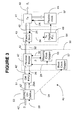
- Figure 3 shows the block diagram of the transmitter side of the transparent reverse synchronizer, or desynchronizer 40 .
- the desynchronizer 40 performs the inverse function performed by the synchronizer 20 , in a very similar manner, and is provided with similar blocks.
- a SONET overhead demultiplexer 53 delineates the SONET overhead from signal 42' using STS-192 clock 28 , which is locked to the rest of the shelf in the usual manner.
- a transmitter overhead FIFO 51 is reset synchronously once each frame with clock 28A .
- Overhead FIFO 51 absorbs overhead locations so as to present to the mapper 47 the data 42' received in the payload, comprising data bits together with the fixed stuff bits and adaptive stuff bits.
- the transmitter OH FIFO 51 could have a similar depth with that of receiver OH FIFO 31 of synchronizer 20.
- the required depth is, as in the case of FIFO 31 , 192x8x12 x3 bits.
- FIFO could thus store sufficient data bits so that transmitter OH FIFO 51 is not emptied during the frame phase when the OH is being demultiplexed from the bit stream.
- the transmitter OH FIFO 51 must have additional depth to tolerate the worst-case series of positive or negative pointer adjustment events.
- a reverse mapping unit 50 comprises a reverse mapper 47 , a mapping clock gapper 55, and a block clock gapper 57 .
- Block clock gapper 57 gaps the STS-192 clock 28 to create block clock 26 .
- Block clock 26 as in the case of the synchronizer 20 , has 1,201,728 cycles per frame, with 42,432 gaps spread evenly across the frame. The gaps account for fields 2, 6 and 14 of Figure 1B. In other words, this clock rejects the TOH and the fixed stuff bits.
- Block clock gapper 57 of the desynchronizer also includes/deletes gaps for pointer adjustments. These inclusions must be spread out for three frames to minimize the phase hit from a pointer adjustment.
- Mapping clock gapper 55 receives the block clock 26 and ⁇ , read from an in-band OH channel within the block. Using ⁇ , gapped clock 26 is further gapped to produce the mapping clock 32 . Mapping clock 32 gaps-out data bits 42' so that strictly trib data bits 42 are clocked out.
- Bits 42 are next processed by a transmitter buffer unit 54 , which comprises an elastic store 43 and a transmitter digital PLL 49 .
- the trib data bits 42 are clocked into the output elastic store 43 using mapping clock 32 .
- the elastic store 43 is emptied by the data clock 24, output by the flexible clock recovery circuit 45 .
- the phase of the output elastic store 43 is sampled periodically by the transmitter digital PLL.
- the sample 34 is processed digitally, and an output signal passed to the flexible clock circuit 45 , to control the voltage of the VCO.
- the flexible clock circuit 45 is of a similar type with the flexible clock circuit 25 of the synchronizer, and provides data clock 24 .
- the bandwidth of the Tx PLL 49 must be as low as possible to filter out jitter from the mapping and from pointer adjustments, and yet high enough to suppress the VCO noise.
Landscapes
- Engineering & Computer Science (AREA)
- Computer Networks & Wireless Communication (AREA)
- Signal Processing (AREA)
- Time-Division Multiplex Systems (AREA)
Abstract
Description
| Determination of α | |||||||||||||||||||
| β | α | ||||||||||||||||||
| β1 | β2 | β3 | β4 | β5 | β6 | β7 | β8 | β9 | β10 | β10 | β9 | β8 | β7 | β6 | β5 | β4 | β3 | β2 | β1 |
| 0 | 0 | 0 | 0 | 0 | 1 | 1 | 1 | 1 | 1 | 1 | 1 | 1 | 1 | 1 | 0 | 0 | 0 | 0 | 0 |
| 1 | 0 | 1 | 0 | 1 | 0 | 1 | 0 | 1 | 0 | 0 | 1 | 0 | 1 | 0 | 1 | 0 | 1 | 0 | 1 |
| 0 | 1 | 1 | 1 | 0 | 0 | 1 | 0 | 0 | 0 | 0 | 0 | 0 | 1 | 0 | 0 | 1 | 1 | 1 | 0 |
| Determination of D for a given C | ||||||||||||||||||||
| C1,2...n Counter of bits in the block | D1,2...n Bit-wise transition Δ of C | |||||||||||||||||||
| C1 | C2 | C3 | C4 | C5 | C6 | C7 | C8 | C9 | C10 | D1 | D2 | D3 | D4 | D5 | D6 | D7 | D8 | D9 | D10 | |
| C-1 | 1 | 0 | 0 | 0 | 0 | 0 | 0 | 0 | 0 | 0 | 1 | 0 | 0 | 0 | 0 | 0 | 0 | 0 | 0 | 0 |
| C | 1 | 0 | 0 | 0 | 0 | 0 | 0 | 0 | 0 | 1 | 0 | 0 | 0 | 0 | 0 | 0 | 0 | 0 | 0 | 1 |
| C+ 1 | 1 | 0 | 0 | 0 | 0 | 0 | 0 | 0 | 1 | 0 | 0 | 0 | 0 | 0 | 0 | 0 | 0 | 0 | 1 | 0 |
| C+ 2 | 1 | 0 | 0 | 0 | 0 | 0 | 0 | 0 | 1 | 1 | 0 | 0 | 0 | 0 | 0 | 0 | 0 | 0 | 0 | 1 |
| Example of flexible mapping for a 7-bit block, for a 3-bit β | ||||||||||
| β | 000 | 001 | 010 | 011 | 100 | 101 | 110 | 111 | ||
| α | 000 | 100 | 010 | 110 | 001 | 101 | 011 | 111 | ||
| C | D | Valid(C,0) | Valid(C,1) | Valid(C,2) | Valid(C,3) | Valid(C,4) | Valid(C,5) | Valid(C,6) | Valid(C,7) | |
| 1 | 001 | 001 | Stuff | Stuff | Stuff | Stuff | Data | Data | Data | Data |
| 2 | 010 | 010 | Stuff | Stuff | Data | Data | Stuff | Stuff | Data | Data |
| 011 | 001 | Stuff | Stuff | Stuff | Stuff | Data | Data | Data | Data | |
| 4 | 100 | 100 | Stuff | Data | Stuff | Data | Stuff | Data | Stuff | Data |
| 101 | 001 | Stuff | Stuff | Stuff | Stuff | Data | Data | Data | Data | |
| 110 | 010 | Stuff | Stuff | Data | Data | Stuff | Stuff | Data | Data | |
| 7 | 111 | 001 | Stuff | Stuff | Stuff | Stuff | Data | Data | Data | Data |
Data, Stuff, Data, Data, Data, Stuff, Data
| Adaptive Stuff algorithm for five consecutive 7-bit blocks, | ||||||||||
| β | 000 | 001 | 010 | 011 | 100 | 101 | 110 | 111 | ||
| α | 000 | 100 | 010 | 110 | 001 | 101 | 011 | 111 | ||
| C | D | Valid(C,0) | Valid(C,1) | Valid(C,2) | Valid(C,3) | Valid(C,4) | Valid(C,5) | Valid(C,6) | Valid(C,7) | |
| 1 | 001 | 001 | Stuff | Stuff | Stuff | Stuff | Data | Data | Data | Data |
| 2 | 010 | 010 | Stuff | Stuff | Data | Data | Stuff | Stuff | Data | Data |
| 3 | 011 | 001 | Stuff | Stuff | Stuff | Stuff | Data | Data | Data | Data |
| 4 | 100 | 100 | Stuff | Data | Stuff | Data | Stuff | Data | Stuff | Data |
| 5 | 101 | 001 | Stuff | Stuff | Stuff | Stuff | Data | Data | Data | Data |
| 6 | 110 | 010 | Stuff | Stuff | Data | Data | Stuff | Stuff | Data | Data |
| 7 | 111 | 001 | Stuff | Stuff | Stuff | Stuff | Data | Data | Data | Data |
| 1 | 001 | 001 | Stuff | Stuff | Stuff | Stuff | Data | Data | Data | Data |
| 2 | 010 | 010 | Stuff | Stuff | Data | Data | Stuff | Stuff | Data | Data |
| 3 | 011 | 001 | Stuff | Stuff | Stuff | Stuff | Data | Data | Data | Data |
| 4 | 100 | 100 | Stuff | Data | Stuff | Data | Stuff | Data | Stuff | Data |
| 5 | 101 | 001 | Stuff | Stuff | Stuff | Stuff | Data | Data | Data | Data |
| 6 | 110 | 010 | Stuff | Stuff | Data | Data | Stuff | Stuff | Data | Data |
| 7 | 111 | 001 | Stuff | Stuff | Stuff | Stuff | Data | Data | Data | Data |
| 1 | 001 | 001 | Stuff | Stuff | Stuff | Stuff | Data | Data | Data | Data |
| 2 | 010 | 010 | Stuff | Stuff | Data | Data | Stuff | Stuff | Data | Data |
| 3 | 011 | 001 | Stuff | Stuff | Stuff | Stuff | Data | Data | Data | Data |
| 4 | 100 | 100 | Stuff | Data | Stuff | Data | Stuff | Data | Stuff | Data |
| 5 | 101 | 001 | Stuff | Stuff | Stuff | Stuff | Data | Data | Data | Data |
| 6 | 110 | 010 | Stuff | Stuff | Data | Data | Stuff | Stuff | Data | Data |
| 7 | 111 | 001 | Stuff | Stuff | Stuff | Stuff | Data | Data | Data | Data |
| 1 | 001 | 001 | Stuff | Stuff | Stuff | Stuff | Data | Data | Data | Data |
| 2 | 010 | 010 | Stuff | Stuff | Data | Data | Stuff | Stuff | Data | Data |
| 3 | 011 | 001 | Stuff | Stuff | Stuff | Stuff | Data | Data | Data | Data |
| 4 | 100 | 100 | Stuff | Data | Stuff | Data | Stuff | Data | Stuff | Data |
| 5 | 101 | 001 | Stuff | Stuff | Stuff | Stuff | Data | Data | Data | Data |
| 6 | 110 | 010 | Stuff | Stuff | Data | Data | Stuff | Stuff | Data | Data |
| 7 | 111 | 001 | Stuff | Stuff | Stuff | Stuff | Data | Data | Data | Data |
| 1 | 001 | 001 | Stuff | Stuff | Stuff | Stuff | Data | Data | Data | Data |
| 2 | 010 | 010 | Stuff | Stuff | Data | Data | Stuff | Stuff | Data | Data |
| 3 | 011 | 001 | Stuff | Stuff | Stuff | Stuff | Data | Data | Data | Data |
| 4 | 100 | 100 | Stuff | Data | Stuff | Data | Stuff | Data | Stuff | Data |
| 5 | 101 | 001 | Stuff | Stuff | Stuff | Stuff | Data | Data | Data | Data |
| 6 | 110 | 010 | Stuff | Stuff | Data | Data | Stuff | Stuff | Data | Data |
| 7 | 111 | 001 | Stuff | Stuff | Stuff | Stuff | Data | Data | Data | Data |
DSDDDSD DDDSDDD DSDDDSD DSDDDSD DDDSDDD
where D stands for data, and S for Stuff. To avoid confusion between D and S above, they are written in regular characters, while italic characters are used for signals S, and for D, bit-wise transition Δ of C.
Claims (20)
- A method for transmitting a continuous digital signal of an arbitrary rate R1 over a synchronous network as a transparent tributary, comprising:wherein said invalid timeslots are uniformly interspersed across said frame.selecting a fixed length container signal of a rate R, where R is higher than said arbitrary rate R1 of said continuous signal; andat a transmit site, distributing the bits of said continuous signal into valid timeslots of a frame of said container signal and providing stuff bits into invalid timeslots,
- A method as claimed in claim 1, wherein said container signal is a SONET/SDH signal, and said synchronous network is a SONET/SDH network.
- A method as claimed in claim 2, wherein said SONET/SDH signal further comprises a synchronous tributary.
- A method as claimed in claim 2, wherein said SONET/SDH signal comprises a plurality of transparent tributaries.
- A method as claimed in any preceding claim, wherein said invalid timeslots comprise one of a fixed stuff and an adaptive stuff bit.
- A method as claimed in claim 5, wherein said step of distributing comprises:receiving a continuous stream of data bits and determining the phase difference between said arbitrary rate R1 and said rate R;adding to said continuous stream a definite number of timeslots for accommodating said fixed stuff bits within said frame, and an adjustable number of timeslots for accommodating said adaptive stuff bits within said frame, based on said phase difference.
- A method as claimed in claim 6, wherein said adjustable number is substantially larger than said definite number.
- A method as claimed in claim 6, wherein said definite number includes transport overhead TOH timeslots and reminder fixed stuff bits timeslots.
- A method as claimed in claim 8, further comprising providing maintenance, operation, administration and provisioning information in said TOH timeslots.
- A method as claimed in any one of claims 6 to 9, wherein said step of adding comprises:partitioning said frame into a number of equally sized data blocks and said definite number of timeslots;
for each block,determining the number of fixed stuff bits and evenly distributing said fixed stuff bits within said block;determining a control function β indicative of said adjustable number; andevenly mapping said fixed stuff bits and said adaptive stuff bits uniformly within a next block based on said control function. - A method as claimed in claim 10, wherein said step of mapping comprises:providing a counter C for identifying a timeslot in said block;defining the binary bit reversal α of said control function β;calculating the bitwise transition delta of said counter C; anddetermining if a timeslot identified by said counter C is an invalid timeslot, whenever a function Valid (C,β) is false; andproviding an adaptive stuff bit into said invalid timeslot.
- A method as claimed in any preceding claim, further comprising recovering said continuous signal from said synchronous signal at a receive site, by extracting the data bits of said continuous signal from said valid timeslots of said frame.
- A synchronizer (20) for mapping a continuous format signal of an arbitrary rate for transport over a synchronous network as a transparent tributary signal, comprising:a data recovery unit (36) for receiving said continuous format signal and recovering a stream of data bits and a data clock indicative of said arbitrary rate;a receiver buffer unit (38) for receiving said stream of data bits, determining a phase difference between said arbitrary rate and the rate of a frame of said tributary, and generating a control function β;a mapping unit (30) for extracting said stream of data bits from said receiver buffer unit at a mapping clock rate, and uniformly distributing a count of stuff bits and data bits into said frame at a block clock rate according to said control function β.
- A synchronizer as claimed in claim 13, wherein said receiver buffer unit comprises:an elastic store (23) for temporarily storing an amount of data bits of said stream at said data clock and providing said data bits to said mapping unit (30) at said block clock rate;a digital PLL (29) for determining the phase difference between said arbitrary rate and said mapping clock and providing said control function β.
- A synchronizer as claimed in claim 13 or 14, wherein said data recovery unit (36) comprises a frequency agile PLL (25) for detecting said arbitrary rate, and a receiver (21) for detecting said data bits using said data clock.
- A synchronizer as claimed in claim 13, 14 or 15 wherein said mapping unit (30) comprises:a block clock gapper (37) for receiving a clock indicative of the rate of said synchronous frame and providing said block clock of a block rate accounting for all timeslots of said synchronous frame and with gapps accounting for a definite number of timeslots for accommodating fixed stuff bits;a mapping clock gapper (35) for receiving said block clock and said control signal β and providing a mapping clock of a mapping rate accounting for all timeslots of said synchronous frame and with gapps accounting for an adjustable number of timeslots for accommodating adaptive stuff bits within said frame; anda mapper (27) for receiving said block clock and said mapping clock and accordingly mapping said stream of data bits in said frame.
- A synchronizer as claimed in any one of claims 13 to 16, further comprising a receiver OH FIFO (31) for re-arranging a plurality of transport overhead TOH timeslots for seamless transport of said frame within said synchronous network.
- A synchronizer as claimed in claim 17, further comprising an overhead multiplexer (33) for adding operation, administration, maintenance and provisioning data into said TOH timeslots.
- A de-synchronizer for reverse mapping a continuous format signal of an arbitrary rate received over a synchronous network as a transparent tributary signal, comprising:a reverse mapping unit (50) for receiving a frame of said tributary at a block clock rate and a control function β, and extracting a stream of data bits at a mapping clock rate, while excluding stuff bits according to said control function β;a transmitter buffer unit (54) for receiving said data bits, and determining a phase difference between said arbitrary rate and the rate of said frame; anda data transmit unit (52) for receiving said data bits and transmitting said continuous format signal at a data rate controlled by said phase difference.
- A de-synchronizer as claimed in claim 19, wherein said control function β is received in said frame.
Applications Claiming Priority (2)
| Application Number | Priority Date | Filing Date | Title |
|---|---|---|---|
| US09/349,087 US7002986B1 (en) | 1999-07-08 | 1999-07-08 | Mapping arbitrary signals into SONET |
| US349087 | 1999-07-08 |
Publications (3)
| Publication Number | Publication Date |
|---|---|
| EP1067722A2 true EP1067722A2 (en) | 2001-01-10 |
| EP1067722A3 EP1067722A3 (en) | 2002-10-02 |
| EP1067722B1 EP1067722B1 (en) | 2007-08-15 |
Family
ID=23370856
Family Applications (1)
| Application Number | Title | Priority Date | Filing Date |
|---|---|---|---|
| EP00305782A Expired - Lifetime EP1067722B1 (en) | 1999-07-08 | 2000-07-07 | Mapping arbitrary signals into sonet |
Country Status (5)
| Country | Link |
|---|---|
| US (3) | US7002986B1 (en) |
| EP (1) | EP1067722B1 (en) |
| JP (1) | JP4530385B2 (en) |
| CA (1) | CA2308968C (en) |
| DE (1) | DE60035926T2 (en) |
Cited By (8)
| Publication number | Priority date | Publication date | Assignee | Title |
|---|---|---|---|---|
| EP1267507A1 (en) * | 2001-06-15 | 2002-12-18 | Lucent Technologies Inc. | A method and apparatus for transmitting and receiving multiplex tributary signals |
| EP1100222A3 (en) * | 1999-11-12 | 2003-01-22 | Nortel Networks Limited | Detection of previous section fail for a transparent tributary |
| WO2002089374A3 (en) * | 2001-04-26 | 2003-01-23 | Ibm | Multiple low-speed into single high-speed sdh/sonet channel mapper / framer device and method |
| WO2003032540A3 (en) * | 2001-10-09 | 2003-09-04 | Nortel Networks Ltd | Method and apparatus for digital data synchronization |
| WO2003081818A1 (en) * | 2002-03-27 | 2003-10-02 | Adc Telecommunications Israel Ltd. | Simplified bandwidth handling for sdh/sonet access rings |
| EP1376966A3 (en) * | 2002-06-04 | 2005-12-14 | ECI Telecom Ltd. | Enable pulse generator and method of mapping data using this generator |
| EP1634414A4 (en) * | 2003-06-19 | 2009-08-26 | Cisco Tech Inc | Multi-rate, multi-protocol, multi-port line interface for a multiservice switching platform |
| US7590154B2 (en) * | 2006-09-22 | 2009-09-15 | Applied Micro Circuits Corporation | Sampled accumulation system and method for jitter attenuation |
Families Citing this family (49)
| Publication number | Priority date | Publication date | Assignee | Title |
|---|---|---|---|---|
| US6522671B1 (en) * | 1999-05-10 | 2003-02-18 | Nortel Networks Limited | Protocol independent sub-rate device |
| US7002986B1 (en) * | 1999-07-08 | 2006-02-21 | Nortel Networks Limited | Mapping arbitrary signals into SONET |
| US7173930B2 (en) * | 1999-10-26 | 2007-02-06 | Ciena Corporation | Transparent flexible concatenation |
| US7139743B2 (en) | 2000-04-07 | 2006-11-21 | Washington University | Associative database scanning and information retrieval using FPGA devices |
| US6711558B1 (en) | 2000-04-07 | 2004-03-23 | Washington University | Associative database scanning and information retrieval |
| US6870860B1 (en) * | 2000-04-19 | 2005-03-22 | Ciena Corporation | Semi-transparent time division multiplexer/demultiplexer |
| KR100358382B1 (en) * | 2000-08-28 | 2002-10-25 | 엘지전자 주식회사 | Apparatus for parallel mapping of serial input data in SDH system |
| US20020110157A1 (en) * | 2001-02-14 | 2002-08-15 | Kestrel Solutions | Method and apparatus for providing a gigabit ethernet circuit pack |
| US6816509B2 (en) * | 2001-03-02 | 2004-11-09 | Ciena Corporation | Data mapper and method for flexible mapping of control and data information within a SONET payload |
| JP3570507B2 (en) * | 2001-03-28 | 2004-09-29 | 日本電気株式会社 | STM mapping circuit and method |
| ITMI20010726A1 (en) * | 2001-04-05 | 2002-10-05 | Cit Alcatel | METHOD AND APPARATUS TO MAP FAST ETHERNET DATA INTERFACES IN A SINGLE VC-4 VIRTUAL CONTAINER OF A STM-1 / OC-3 PAYLOAD TRANSMITTED IN U |
| US20030048813A1 (en) * | 2001-09-05 | 2003-03-13 | Optix Networks Inc. | Method for mapping and multiplexing constant bit rate signals into an optical transport network frame |
| US7716330B2 (en) * | 2001-10-19 | 2010-05-11 | Global Velocity, Inc. | System and method for controlling transmission of data packets over an information network |
| WO2003043240A1 (en) * | 2001-11-13 | 2003-05-22 | Fujitsu Limited | Virtual concatenation transmission method and device |
| US7227876B1 (en) * | 2002-01-28 | 2007-06-05 | Pmc-Sierra, Inc. | FIFO buffer depth estimation for asynchronous gapped payloads |
| US20030225802A1 (en) * | 2002-06-02 | 2003-12-04 | Eci Telecom Ltd. | Enable generator EG, and method of mapping data using the EG |
| US7711844B2 (en) | 2002-08-15 | 2010-05-04 | Washington University Of St. Louis | TCP-splitter: reliable packet monitoring methods and apparatus for high speed networks |
| EP1416656B1 (en) * | 2002-11-01 | 2014-01-08 | Broadcom Corporation | Transceiver system and method supporting variable rates and multiple protocols |
| US7324548B2 (en) * | 2002-11-01 | 2008-01-29 | Broadcom Corporation | Transceiver system and method supporting variable rates and multiple protocols |
| JP3886891B2 (en) | 2002-12-10 | 2007-02-28 | 富士通株式会社 | COMMUNICATION SYSTEM, COMMUNICATION DEVICE AND NETWORK MANAGEMENT DEVICE USED IN THE COMMUNICATION SYSTEM |
| US20040114636A1 (en) * | 2002-12-13 | 2004-06-17 | General Instrument Corporation | Asynchronous data multiplexer |
| WO2004088889A1 (en) * | 2003-03-31 | 2004-10-14 | Fujitsu Limited | Transparent multiplexing method and device |
| CN2671239Y (en) * | 2003-12-05 | 2005-01-12 | 华为技术有限公司 | Synchronous digital transmitting system branch unit for supporting multiple service treatment |
| US20070277036A1 (en) | 2003-05-23 | 2007-11-29 | Washington University, A Corporation Of The State Of Missouri | Intelligent data storage and processing using fpga devices |
| US10572824B2 (en) | 2003-05-23 | 2020-02-25 | Ip Reservoir, Llc | System and method for low latency multi-functional pipeline with correlation logic and selectively activated/deactivated pipelined data processing engines |
| US7602785B2 (en) | 2004-02-09 | 2009-10-13 | Washington University | Method and system for performing longest prefix matching for network address lookup using bloom filters |
| KR100566240B1 (en) * | 2004-03-16 | 2006-03-29 | 삼성전자주식회사 | Subscriber Distribution Device in Optical Subscriber Network using IEEE1394 |
| JP4230968B2 (en) * | 2004-07-20 | 2009-02-25 | 株式会社日立ハイテクノロジーズ | Charged particle beam equipment |
| JP4417807B2 (en) * | 2004-08-25 | 2010-02-17 | 株式会社東芝 | Elastic buffer |
| CA2599382A1 (en) | 2005-03-03 | 2006-09-14 | Washington University | Method and apparatus for performing biosequence similarity searching |
| US7702629B2 (en) * | 2005-12-02 | 2010-04-20 | Exegy Incorporated | Method and device for high performance regular expression pattern matching |
| US7954114B2 (en) | 2006-01-26 | 2011-05-31 | Exegy Incorporated | Firmware socket module for FPGA-based pipeline processing |
| WO2007092630A2 (en) * | 2006-02-09 | 2007-08-16 | Flextronics International Usa, Inc. | Data processing systems and methods |
| US7746903B2 (en) * | 2006-03-07 | 2010-06-29 | Harris Corporation | SONET management and control channel improvement |
| US7840482B2 (en) | 2006-06-19 | 2010-11-23 | Exegy Incorporated | Method and system for high speed options pricing |
| US7826490B2 (en) * | 2006-06-29 | 2010-11-02 | Applied Micro Circuits Corporation | System and method for synchronous payload envelope mapping without pointer adjustments |
| US7809022B2 (en) * | 2006-10-23 | 2010-10-05 | Harris Corporation | Mapping six (6) eight (8) mbit/s signals to a SONET frame |
| US7660793B2 (en) | 2006-11-13 | 2010-02-09 | Exegy Incorporated | Method and system for high performance integration, processing and searching of structured and unstructured data using coprocessors |
| US8326819B2 (en) | 2006-11-13 | 2012-12-04 | Exegy Incorporated | Method and system for high performance data metatagging and data indexing using coprocessors |
| US7725469B2 (en) * | 2007-08-23 | 2010-05-25 | International Business Machines Corporation | System and program products for pruning objects in a service registry and repository |
| JP5835059B2 (en) * | 2012-03-29 | 2015-12-24 | 富士通株式会社 | Data transmission apparatus and data transmission method |
| US9088380B2 (en) | 2012-05-31 | 2015-07-21 | Ciena Corporation | Optical transport network generic non-client specific protection systems and methods |
| JP5999182B2 (en) * | 2012-07-20 | 2016-09-28 | 富士通株式会社 | Transmission equipment |
| JP6402562B2 (en) * | 2014-09-30 | 2018-10-10 | 富士通株式会社 | Optical transmission apparatus and transmission frame generation method |
| JP6467923B2 (en) * | 2015-01-06 | 2019-02-13 | 日本電気株式会社 | TS data reading device and TS data reading method |
| JP6290852B2 (en) * | 2015-12-24 | 2018-03-07 | 日本電気株式会社 | Signal configuration apparatus, signal configuration system, signal configuration method, and signal configuration program |
| WO2018119035A1 (en) | 2016-12-22 | 2018-06-28 | Ip Reservoir, Llc | Pipelines for hardware-accelerated machine learning |
| US10985837B2 (en) | 2019-06-17 | 2021-04-20 | Ciena Corporation | Generic non-client specific protection via TCM status and enhanced OTN network propagation of client faults |
| US11309984B2 (en) | 2020-03-04 | 2022-04-19 | Ciena Corporation | TCM control for physical layer on OTU ports |
Family Cites Families (32)
| Publication number | Priority date | Publication date | Assignee | Title |
|---|---|---|---|---|
| US3872257A (en) * | 1974-03-11 | 1975-03-18 | Bell Telephone Labor Inc | Multiplex and demultiplex apparatus for digital-type signals |
| JPH0414681Y2 (en) * | 1986-04-11 | 1992-04-02 | ||
| CA1262173A (en) | 1986-05-29 | 1989-10-03 | James Angus Mceachern | Synchronization of asynchronous data signals |
| US4791652A (en) | 1987-06-04 | 1988-12-13 | Northern Telecom Limited | Synchronization of asynchronous data signals |
| US4967405A (en) * | 1988-12-09 | 1990-10-30 | Transwitch Corporation | System for cross-connecting high speed digital SONET signals |
| US4998242A (en) * | 1988-12-09 | 1991-03-05 | Transwitch Corp. | Virtual tributary cross connect switch and switch network utilizing the same |
| JPH0654901B2 (en) * | 1989-02-08 | 1994-07-20 | 富士通株式会社 | Format conversion control method |
| WO1990013955A1 (en) * | 1989-04-28 | 1990-11-15 | Anritsu Corporation | Signal generator and signal receiver based on synchronous multiplex transmission system |
| US4928275A (en) | 1989-05-26 | 1990-05-22 | Northern Telecom Limited | Synchronization of asynchronous data signals |
| CA1326719C (en) * | 1989-05-30 | 1994-02-01 | Telecommunications Research Laboratories | Ds3 to 28 vt1.5 sonet interface circuit |
| US5131013A (en) * | 1990-05-30 | 1992-07-14 | At&T Bell Laboratories | Asynchronous-synchronous digital transmission signal conversion |
| DE4027967A1 (en) * | 1990-09-04 | 1992-03-05 | Philips Patentverwaltung | PLUG DECISION CIRCUIT FOR A BITRATE ADJUSTMENT ARRANGEMENT |
| JPH05292055A (en) * | 1992-04-13 | 1993-11-05 | Matsushita Electric Ind Co Ltd | Staff synchronizing device |
| JP3150412B2 (en) * | 1992-05-06 | 2001-03-26 | 富士通株式会社 | SDH accommodating method of asynchronous 32Mb / s signal |
| JPH06261055A (en) * | 1993-03-03 | 1994-09-16 | Mitsubishi Electric Corp | Relay device |
| US5428641A (en) | 1993-07-23 | 1995-06-27 | Motorola, Inc. | Device and method for utilizing zero-padding constellation switching with frame mapping |
| JPH07264152A (en) * | 1994-03-18 | 1995-10-13 | Fujitsu Ltd | Frame mapping / demapping method |
| US5453780A (en) * | 1994-04-28 | 1995-09-26 | Bell Communications Research, Inc. | Continous presence video signal combiner |
| JP3376144B2 (en) * | 1994-12-28 | 2003-02-10 | 日本電気株式会社 | Optical network device and optical transmission system |
| US5889781A (en) | 1996-06-11 | 1999-03-30 | Vlsi Technology | Asynchronous timing generator |
| US5784594A (en) | 1996-06-12 | 1998-07-21 | Lucent Technologies Inc. | Generic interactive device model wrapper |
| JP3031251B2 (en) * | 1996-07-08 | 2000-04-10 | 日本電気株式会社 | Low-speed transmission signal interface unit with internal monitoring function and its internal fault monitoring method |
| JPH10145321A (en) * | 1996-11-05 | 1998-05-29 | Fujitsu Ltd | SDH transmission system and alarm transmission control method |
| US6047005A (en) * | 1998-01-07 | 2000-04-04 | Mci Communications Corporation | Virtual bearer channel platform for processing service requests received in the form of channel data |
| US6240087B1 (en) * | 1998-03-31 | 2001-05-29 | Alcatel Usa Sourcing, L.P. | OC3 delivery unit; common controller for application modules |
| US7002986B1 (en) * | 1999-07-08 | 2006-02-21 | Nortel Networks Limited | Mapping arbitrary signals into SONET |
| US6829247B1 (en) * | 1999-12-23 | 2004-12-07 | Nortel Networks Limited | Method and apparatus for establishing dedicated local area network N) connections in an optical transmission network |
| US6870860B1 (en) * | 2000-04-19 | 2005-03-22 | Ciena Corporation | Semi-transparent time division multiplexer/demultiplexer |
| EP1246383A1 (en) * | 2001-03-28 | 2002-10-02 | Lucent Technologies Inc. | Data transmission system |
| US7277447B2 (en) * | 2001-03-30 | 2007-10-02 | Redback Networks Inc. | Onboard RAM based FIFO with pointers to buffer overhead bytes of synchronous payload envelopes in synchronous optical networks |
| US7158517B2 (en) * | 2001-05-21 | 2007-01-02 | Intel Corporation | Method and apparatus for frame-based protocol processing |
| US7362759B2 (en) * | 2001-05-21 | 2008-04-22 | Intel Corporation | Method and apparatus for encoding information |
-
1999
- 1999-07-08 US US09/349,087 patent/US7002986B1/en not_active Expired - Lifetime
-
2000
- 2000-05-18 CA CA2308968A patent/CA2308968C/en not_active Expired - Lifetime
- 2000-07-06 JP JP2000204447A patent/JP4530385B2/en not_active Expired - Fee Related
- 2000-07-07 EP EP00305782A patent/EP1067722B1/en not_active Expired - Lifetime
- 2000-07-07 DE DE60035926T patent/DE60035926T2/en not_active Expired - Lifetime
-
2002
- 2002-04-18 US US10/124,235 patent/US7257117B2/en not_active Expired - Lifetime
-
2005
- 2005-11-30 US US11/289,351 patent/US7286564B2/en not_active Expired - Fee Related
Cited By (13)
| Publication number | Priority date | Publication date | Assignee | Title |
|---|---|---|---|---|
| EP1100222A3 (en) * | 1999-11-12 | 2003-01-22 | Nortel Networks Limited | Detection of previous section fail for a transparent tributary |
| US6937614B1 (en) | 1999-11-12 | 2005-08-30 | Nortel Networks Limited | Transparent port for high rate networking |
| US7630414B2 (en) | 2001-04-26 | 2009-12-08 | International Business Machines Corporation | Multiple low-speed into single high-speed SDH/SONET channel mapper/framer device and method |
| WO2002089374A3 (en) * | 2001-04-26 | 2003-01-23 | Ibm | Multiple low-speed into single high-speed sdh/sonet channel mapper / framer device and method |
| EP1267507A1 (en) * | 2001-06-15 | 2002-12-18 | Lucent Technologies Inc. | A method and apparatus for transmitting and receiving multiplex tributary signals |
| US7254207B2 (en) | 2001-06-15 | 2007-08-07 | Lucent Technologies Inc. | Method and apparatus for transmitting and recieving multiplex tributary signals |
| WO2003032540A3 (en) * | 2001-10-09 | 2003-09-04 | Nortel Networks Ltd | Method and apparatus for digital data synchronization |
| US7023942B1 (en) | 2001-10-09 | 2006-04-04 | Nortel Networks Limited | Method and apparatus for digital data synchronization |
| WO2003081818A1 (en) * | 2002-03-27 | 2003-10-02 | Adc Telecommunications Israel Ltd. | Simplified bandwidth handling for sdh/sonet access rings |
| EP1376966A3 (en) * | 2002-06-04 | 2005-12-14 | ECI Telecom Ltd. | Enable pulse generator and method of mapping data using this generator |
| EP1634414A4 (en) * | 2003-06-19 | 2009-08-26 | Cisco Tech Inc | Multi-rate, multi-protocol, multi-port line interface for a multiservice switching platform |
| EP2416534A3 (en) * | 2003-06-19 | 2012-05-02 | Cisco Technology, Inc. | Multi-rate, multi-protocol, multi-port line interface for a multiservice switching platform |
| US7590154B2 (en) * | 2006-09-22 | 2009-09-15 | Applied Micro Circuits Corporation | Sampled accumulation system and method for jitter attenuation |
Also Published As
| Publication number | Publication date |
|---|---|
| CA2308968A1 (en) | 2001-01-08 |
| DE60035926D1 (en) | 2007-09-27 |
| US20060088061A1 (en) | 2006-04-27 |
| EP1067722B1 (en) | 2007-08-15 |
| US7002986B1 (en) | 2006-02-21 |
| DE60035926T2 (en) | 2007-12-06 |
| US7286564B2 (en) | 2007-10-23 |
| JP4530385B2 (en) | 2010-08-25 |
| US20020159473A1 (en) | 2002-10-31 |
| US7257117B2 (en) | 2007-08-14 |
| CA2308968C (en) | 2010-01-26 |
| JP2001069104A (en) | 2001-03-16 |
| EP1067722A3 (en) | 2002-10-02 |
Similar Documents
| Publication | Publication Date | Title |
|---|---|---|
| US7002986B1 (en) | Mapping arbitrary signals into SONET | |
| CA2322908C (en) | Semi transparent tributary for synchronous transmission | |
| EP1052794B1 (en) | Protocol independent sub-rate device | |
| US20020186719A1 (en) | Pointer adjustment wander and jitter reduction apparatus for a desynchronizer | |
| EP1965528A1 (en) | Optical transmission system and method | |
| EP1436923B1 (en) | Method and apparatus for digital data synchronization | |
| US7239649B2 (en) | Transmission system | |
| US6633584B1 (en) | Payload translation between frame options in synchronous digital hierarchy networks | |
| US7711007B2 (en) | Method and apparatus for synchronous switching of optical transport network signals | |
| US7688833B2 (en) | Synchronous transmission network node | |
| WO2008127383A1 (en) | An efficient scalable implementation of vcat/lcas for sdh and pdh signals | |
| EP0699363B1 (en) | Method and device for making a justification decision at a node of a synchronous digital telecommunication system | |
| EP1047214A2 (en) | Multiplex structures for communications system | |
| EP0648394B1 (en) | Method for receiving a signal used in a synchronous digital telecommunication system | |
| US7715443B1 (en) | Boundary processing between a synchronous network and a plesiochronous network | |
| Dutta et al. | Grooming mechanisms in SONET/SDH and next-generation SONET/SDH | |
| CA2289897A1 (en) | Multiplex hierarchy for high capacity transport systems | |
| WO1994003000A1 (en) | Method for receiving a signal used in a synchronous digital telecommunication system |
Legal Events
| Date | Code | Title | Description |
|---|---|---|---|
| PUAI | Public reference made under article 153(3) epc to a published international application that has entered the european phase |
Free format text: ORIGINAL CODE: 0009012 |
|
| AK | Designated contracting states |
Kind code of ref document: A2 Designated state(s): AT BE CH CY DE DK ES FI FR GB GR IE IT LI LU MC NL PT SE |
|
| AX | Request for extension of the european patent |
Free format text: AL;LT;LV;MK;RO;SI |
|
| PUAL | Search report despatched |
Free format text: ORIGINAL CODE: 0009013 |
|
| AK | Designated contracting states |
Kind code of ref document: A3 Designated state(s): AT BE CH CY DE DK ES FI FR GB GR IE IT LI LU MC NL PT SE |
|
| AX | Request for extension of the european patent |
Free format text: AL;LT;LV;MK;RO;SI |
|
| 17P | Request for examination filed |
Effective date: 20030305 |
|
| AKX | Designation fees paid |
Designated state(s): DE FR GB |
|
| RAP1 | Party data changed (applicant data changed or rights of an application transferred) |
Owner name: NORTEL NETWORKS LIMITED |
|
| 17Q | First examination report despatched |
Effective date: 20031230 |
|
| GRAP | Despatch of communication of intention to grant a patent |
Free format text: ORIGINAL CODE: EPIDOSNIGR1 |
|
| GRAS | Grant fee paid |
Free format text: ORIGINAL CODE: EPIDOSNIGR3 |
|
| GRAA | (expected) grant |
Free format text: ORIGINAL CODE: 0009210 |
|
| AK | Designated contracting states |
Kind code of ref document: B1 Designated state(s): DE FR GB |
|
| REG | Reference to a national code |
Ref country code: GB Ref legal event code: FG4D |
|
| REF | Corresponds to: |
Ref document number: 60035926 Country of ref document: DE Date of ref document: 20070927 Kind code of ref document: P |
|
| PLBE | No opposition filed within time limit |
Free format text: ORIGINAL CODE: 0009261 |
|
| STAA | Information on the status of an ep patent application or granted ep patent |
Free format text: STATUS: NO OPPOSITION FILED WITHIN TIME LIMIT |
|
| 26N | No opposition filed |
Effective date: 20080516 |
|
| REG | Reference to a national code |
Ref country code: GB Ref legal event code: 732E Free format text: REGISTERED BETWEEN 20101230 AND 20110105 |
|
| REG | Reference to a national code |
Ref country code: FR Ref legal event code: TP |
|
| REG | Reference to a national code |
Ref country code: DE Ref legal event code: R082 Ref document number: 60035926 Country of ref document: DE Representative=s name: KUDLEK & GRUNERT PATENTANWAELTE PARTNERSCHAFT, DE |
|
| REG | Reference to a national code |
Ref country code: DE Ref legal event code: R082 Ref document number: 60035926 Country of ref document: DE Representative=s name: KUDLEK & GRUNERT PATENTANWAELTE PARTNERSCHAFT, DE Effective date: 20120209 Ref country code: DE Ref legal event code: R081 Ref document number: 60035926 Country of ref document: DE Owner name: CIENA LUXEMBOURG S.A.R.L., LU Free format text: FORMER OWNER: NORTEL NETWORKS LTD., MONTREAL, QUEBEC, CA Effective date: 20120209 Ref country code: DE Ref legal event code: R082 Ref document number: 60035926 Country of ref document: DE Representative=s name: KUDLEK & GRUNERT PATENTANWAELTE PARTNERSCHAFT, DE Effective date: 20120207 Ref country code: DE Ref legal event code: R082 Ref document number: 60035926 Country of ref document: DE Representative=s name: KUDLEK GRUNERT & PARTNER PATENTANWAELTE MBB, DE Effective date: 20120209 Ref country code: DE Ref legal event code: R082 Ref document number: 60035926 Country of ref document: DE Representative=s name: KUDLEK GRUNERT & PARTNER PATENTANWAELTE MBB, DE Effective date: 20120207 |
|
| REG | Reference to a national code |
Ref country code: FR Ref legal event code: PLFP Year of fee payment: 16 |
|
| REG | Reference to a national code |
Ref country code: FR Ref legal event code: PLFP Year of fee payment: 17 |
|
| REG | Reference to a national code |
Ref country code: FR Ref legal event code: PLFP Year of fee payment: 18 |
|
| REG | Reference to a national code |
Ref country code: FR Ref legal event code: PLFP Year of fee payment: 19 |
|
| PGFP | Annual fee paid to national office [announced via postgrant information from national office to epo] |
Ref country code: DE Payment date: 20190719 Year of fee payment: 20 Ref country code: FR Payment date: 20190719 Year of fee payment: 20 |
|
| PGFP | Annual fee paid to national office [announced via postgrant information from national office to epo] |
Ref country code: GB Payment date: 20190719 Year of fee payment: 20 |
|
| REG | Reference to a national code |
Ref country code: DE Ref legal event code: R071 Ref document number: 60035926 Country of ref document: DE |
|
| REG | Reference to a national code |
Ref country code: GB Ref legal event code: PE20 Expiry date: 20200706 |
|
| PG25 | Lapsed in a contracting state [announced via postgrant information from national office to epo] |
Ref country code: GB Free format text: LAPSE BECAUSE OF EXPIRATION OF PROTECTION Effective date: 20200706 |