EP1067572A2 - Cathode ray tube with indirectly heated cathode - Google Patents
Cathode ray tube with indirectly heated cathode Download PDFInfo
- Publication number
- EP1067572A2 EP1067572A2 EP00114001A EP00114001A EP1067572A2 EP 1067572 A2 EP1067572 A2 EP 1067572A2 EP 00114001 A EP00114001 A EP 00114001A EP 00114001 A EP00114001 A EP 00114001A EP 1067572 A2 EP1067572 A2 EP 1067572A2
- Authority
- EP
- European Patent Office
- Prior art keywords
- cathode
- base metal
- heater
- diameter
- ray tube
- Prior art date
- Legal status (The legal status is an assumption and is not a legal conclusion. Google has not performed a legal analysis and makes no representation as to the accuracy of the status listed.)
- Withdrawn
Links
Images



Classifications
-
- H—ELECTRICITY
- H01—ELECTRIC ELEMENTS
- H01J—ELECTRIC DISCHARGE TUBES OR DISCHARGE LAMPS
- H01J1/00—Details of electrodes, of magnetic control means, of screens, or of the mounting or spacing thereof, common to two or more basic types of discharge tubes or lamps
- H01J1/02—Main electrodes
- H01J1/13—Solid thermionic cathodes
- H01J1/20—Cathodes heated indirectly by an electric current; Cathodes heated by electron or ion bombardment
- H01J1/26—Supports for the emissive material
-
- H—ELECTRICITY
- H01—ELECTRIC ELEMENTS
- H01J—ELECTRIC DISCHARGE TUBES OR DISCHARGE LAMPS
- H01J29/00—Details of cathode-ray tubes or of electron-beam tubes of the types covered by group H01J31/00
- H01J29/02—Electrodes; Screens; Mounting, supporting, spacing or insulating thereof
- H01J29/04—Cathodes
Definitions
- the present invention relates to a cathode ray tube such as a color picture tube or a color display tube, and particularly to a cathode ray tube having reduced a warm-up time required for formation of an image after a heater has been turned on.
- a cathode ray tube such as a color cathode ray tube used for a monitor at a terminal of office automation equipment, for example, generally has a vacuum envelope comprised of a panel, a neck and a funnel for connecting the panel and the neck, a phosphor screen comprised of three-color phosphor picture elements coated on an inner surface of the panel, and an electron gun housed in the neck.
- the electron gun for the cathode ray tube has three cathodes for generating the three electron beams in a horizontal direction and a plurality of electrodes located downstream of the three cathodes and spaced in the direction of travel of the electron beams for forming a main lens.
- the phosphor screen comprises three-color phosphor picture elements fabricated in the form of dots or stripes and arranged at a predetermined pitch, and a color selection electrode such as a shadow mask is closely spaced from the phosphor screen between the phosphor screen and the electron gun.
- each cathode in the electron gun is provided with an electron-emissive material layer coated on a cathode base metal and a heater for heating the cathode base metal such that electrons are emitted from the electron-emissive material layer.
- FIG. 9 is a fragmentary front view, partly cutaway, of an example of a prior art cathode assembly.
- a plate-shaped cathode base metal 81 is coated with an electron-emissive material layer 82 on its surface and fitted and supported within an end 83a of a cylindrical cathode sleeve 83.
- Reference numeral 84 denotes a plurality of cathode support pieces, usually three cathode support pieces 84 are equally spaced about the circumference of the cathode sleeve 83, are fixed at one end thereof to the other end 83b of the cathode sleeve 83 and are fixed at another end thereof to a cathode support cylinder 85.
- the cathode base metal 81 and the cathode sleeve 83 are fixed together as follows: Initially, a disk of a predetermined diameter slightly smaller than an inside diameter of the cylindrical cathode sleeve 83 is stamped out from material for the cathode base metal 81, is fitted within the end 83a of the cathode sleeve 83, then is pressed at a central portion thereof so as to expand its diameter and thereby to be press-fitted within the cathode sleeve 83. Then the cathode base metal 81 is laser-welded or resistance-welded to the cathode sleeve 83. This construction is disclosed in Japanese Patent Publication No. Sho 54-44551 (published on December 26, 1979), for example.
- the above-explained prior art has an advantage of ease of manufacture obtained by using a disk-shaped cathode base metal, and has considered improvement in speedup of electron emission by fitting the cathode base metal within the cathode sleeve, but no consideration has been given to reduction of rise time of electron emission (reduction of the image-forming warm-up time in cathode ray tubes such as color display tubes) by improving the configuration of the cathode sleeve or the heaters.
- the image-forming warm-up time in a cathode ray tube is a time required for the electron-emissive material layer to reach a required temperature and is determined by the heat capacity of the heater-cathode system.
- the outside diameter of a coiled portion of a heater is smaller at a top portion thereof opposing the cathode base metal than that of the coiled portion on a side of legs of the heater, and when the heater is inserted into the prior art cathode sleeve of a uniform inside diameter over its entire length, a space is produced between the coiled portion and the wall of the cathode sleeve in the vicinity of the top portion of the coiled portion near the cathode base metal, therefore the heat transfer from the heater to the cathode sleeve is delayed and consequently, the image-forming warm-up time cannot be reduced.
- a time required for the screen brightness to reach 50 % of the required brightness is limited to eight seconds or less (or a time required for the phosphor screen to become faintly luminous must be limited to three to four seconds) after power turn on, and if the time exceeds eight seconds, the operator sometimes feels irritated.
- Power saving is also essential in view of energy saving and the protection of environment, and therefore there is a demand for reduction of the image-forming warm-up time after heater power turn on following the waiting time.
- the present invention solves the above problems, and it is an object of the present invention to provide a cathode ray tube such as a color display tube employing a cathode assembly of the type having a cathode base metal fitted and fixed within a cathode sleeve and capable of reducing the image-forming warm-up time and retaining the basic characteristics such as long emission life by improving absorption of heat from a heater and preventing thermal loss by radiation.
- a cathode ray tube comprising a vacuum envelope including a panel portion, a neck portion and a funnel portion for connecting the panel portion and the neck portion, a phosphor screen formed on an inner surface of the panel portion, and an electron gun housed in the neck portion and including a cathode and a heater
- the cathode comprising: a disk-shaped cathode base metal having an oxide coating thereon, and a cylindrical cathode sleeve housing the heater, the cylindrical cathode sleeve including a small-diameter portion having the disk-shaped cathode base metal fitted within an end thereof and housing a top portion of the heater and a large-diameter portion housing leg portions of the heater, and an axial length SL (mm) of the small-diameter portion and an outside diameter DD (mm) of the disk-shaped cathode base metal satisfying the following inequality.
- an outside diameter of a heat-generating coiled portion of a usual heater is smaller than that of a leg portion of the heater, when the heater is inserted into the cylindrical cathode sleeve, the side wall of the coiled portion of the heater is brought into intimate contact with or immediate proximity to the small-diameter portion at one end of the cylindrical cathode sleeve, the effect of heat transfer from the heater to the cathode sleeve is heightened, and consequently, heat efficiency is improved.
- FIG.1 is a cross-sectional view showing an overall construction of a shadow mask type color cathode ray tube in accordance with an embodiment of the present invention.
- Reference numeral 11 denotes a panel portion
- 12 is a neck portion
- 13 is a funnel portion
- 14 is a phosphor screen
- 15 is a shadow mask having a large number of electron beam apertures therein
- 16 is a mask frame
- 17 is a magnetic shield
- 18 is a shadow mask suspension mechanism
- 19 is an electron gun for emitting three electron beams, one center electron beam Bc and two side electron beams Bs
- DY is a deflection yoke for deflecting the electron beams horizontally and vertically
- MA is an external magnetic device for adjusting color purity and the like.
- a vacuum envelope comprises the panel portion 11, the funnel portion 13 and the neck portion 12, the phosphor screen 14 is formed on the inner surface of the panel portion 11, the mask frame 16 having the shadow mask 15 and the magnetic shield 17 fixed thereto is suspended within the panel portion 11 by the shadow mask suspension mechanism 18, the panel portion 11 is frit-sealed to the funnel portion 13 by heat-fusing a glass frit, the electron gun 19 is mounted into the neck portion 12 joined to the funnel portion 13, and then the vacuum envelope is sealed off after evacuation of the air therefrom.
- the electron gun 19 employs a cathode assembly explained subsequently.
- the three electron beams Bc, Bs from emitted from the electron gun 19 are deflected in horizontal and vertical directions by the deflection yoke DY around the transition region between the neck portion 12 and the funnel portion 13, and are transmitted through electron beam apertures in the shadow mask 15 serving as a color selection electrode to strike the phosphor picture elements of their intended colors forming the phosphor screen 14 and form an image.
- FIG. 2 is a plan view showing a structural example of an electron gun used for a color cathode ray tube of the present invention.
- Reference numeral 20 denotes a cathode assembly, examples of which will be described in detail subsequently in connection with FIG. 3 and the subsequent figures.
- Reference numeral 21 denotes a first electrode (a control electrode), 22 is a second electrode (an accelerating electrode), 23, 24 and 25 are third, fourth and fifth electrodes (focus electrodes), respectively, 26 is a sixth electrode (an anode), 27 are beading glasses (only one of which is shown), and 28 are stem pins.
- the cathode assembly 20 and the first to sixth electrodes 21 to 26 are coaxially fixed on a pair of beading glasses 27.
- Electron beams emitted from the cathode assembly 20 are appropriately accelerated and focused by the first electrode 21, the second electrode 22, the third electrode 23, the fourth electrode 24, the fifth electrode 25 and the sixth electrode 26, and are projected toward the phosphor screen from the sixth electrode 26.
- the stem pins 28 serve as terminals for applying required voltages or video signals to the respective electrodes forming the electron gun 19.
- FIG. 3 is an enlarged fragmentary cross-sectional view of an essential part of the cathode assembly 20 of the electron gun of FIG. 2.
- the cathode assembly 20 houses a heater 31 which is fixed to heater supports 32 at its lower ends.
- Reference numeral 33 denotes a cathode eyelet, which supports the cathode assembly 20 at its lower end and thereby fixes it at a required position in the electron gun via a bead support 34 for supporting the cathode assembly 20.
- FIG. 4 is an enlarged fragmentary cross-sectional view of an essential part of the cathode assembly of FIG. 3.
- a cathode 40 comprises a disk-shaped cathode base metal 41, an electron-emissive material layer 42 formed on a top surface 41a of the disk-shaped cathode base metal 41 and a cylindrical cathode sleeve 43.
- the cylindrical cathode sleeve 43 has a sidewall of the cathode base metal 41b fitted and fixed within one end 43a thereof, is formed with an opening at the other end 43b thereof for inserting a heater 31 therefrom, and is fixed to a cathode support cylinder 44.
- the cylindrical cathode sleeve 43 has a smallest-diameter portion 43c in the vicinity of the end 43a thereof within which the cathode base metal 41 is fitted and fixed, (a portion below the end 43a in FIG. 4) compared with the entirety of the cylindrical cathode sleeve 43 including the other end 43b. This occurs because a deformation caused by press-fitting the cathode base metal 41 into the cylindrical cathode sleeve 43 from the end 43b is an elastic one.
- the inside diameter of the smallest-diameter portion 43c is slightly smaller than the outside diameter of the cathode base metal 41.
- a coiled portion 31b of the heater 31 is inserted into the smallest-diameter portion 43c.
- Reference numeral 31a denotes a top of the heater 31.
- the other end 43b of the cathode sleeve 43 is flared so as to avoid contact with leg portions 31c of the heater 31.
- the cathode 40 and the cathode support cylinder 44 constitute the cathode assembly 20.
- Reference character CL denotes a centerline of the cylindrical cathode sleeve 43 and the remaining components of the cathode assembly arranged coaxially with the centerline CL.
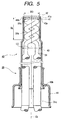
- FIG. 5 is an enlarged fragmentary cross-sectional view of an essential part of another example of a cathode assembly of FIG. 3.
- the same reference numerals as utilized in FIG. 4 designate corresponding portions in FIG. 5.
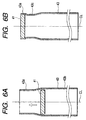
- FIGS. 6A and 6B are cross-sectional views for explaining an example of press-fitting the cathode base metals 41 into the cylindrical cathode sleeves 43 shown in FIGS. 4 and 5, respectively.
- the cylindrical cathode sleeve 43 is made of nichrome containing 20 weight % of chromium (Cr), for example.
- nichrome sleeve of 1.6 mm in outside diameter, 0.02 mm in thickness and 5.0 mm in length is fabricated by drawing, cutting and barrel processing, then the nichrome sleeve is subjected to uniform compression working all around its circumference in a direction perpendicular to the tube axis such that a portion extending 2.0 mm from one end of the nichrome sleeve is formed to have an inside diameter of 1.4 mm (a corresponding outside diameter of 1.44 mm) into the cylindrical cathode sleeve, to complete the cylindrical cathode sleeve 43.
- the cathode base metal 41 is made of material containing nickel (Ni) as a main component, 0.1 weight percent of magnesium (Mg) and 0.05 weight percent of silicon (Si), both of which serve as reducing agents, and is of the disk shape of 0.17 mm in thickness and 1.43 mm in outside diameter fabricated by a normal press-forming technique.
- the thickness of 0.17 mm was adopted in consideration of dispersion of reducing agents relevant to cathode emission life characteristics.
- the cathode base metal 41 is forced into the cylindrical cathode sleeve 43 from the end 43b having the outside diameter of 1.6 mm toward the end 43a having the inside diameter of 1.4 mm, then as shown in FIG. 6B, the cathode base metal 41 is press-fitted to the cylindrical cathode sleeve 43 at the end 43a, and then the cathode base metal 41 and the cylindrical cathode sleeve 43 are welded together at the end 43a by a normal laser or resistance welding technique.
- the disk-shaped cathode base metal 41 having the outside diameter of 1.43 mm is press-fitted into the end 43a having the inside diameter of 1.4 mm, of the cylindrical cathode sleeve 43, and therefore if the cylindrical cathode sleeve 43 has a sufficiently elastic quality, the smallest-diameter portion 43c retaining the original inside diameter of 1.4 mm is present in the vicinity of the fitted and fixed cathode base metal 41 as shown in FIG.
- cylindrical cathode sleeve 43 is softened by heat treatment such that it can be plastically wrought, a portion of the cylindrical cathode sleeve 43 on the end 43a side is expanded to have an approximately uniform diameter throughout the approximately entire portion as shown in FIG. 5.
- the cathode assemblies shown in FIGS. 4 and 5 incorporated into color display tubes, respectively, have shortened the image-forming warm-up time (a time required for the screen brightness to reach 50 % of the required brightness) to 6.5 sec from 7.5 sec in the prior art cathode assembly.
- the present inventors have found by experiments that the image-forming warm-up time is effectively reduced if the following condition is satisfied: 0.5 ⁇ SL/DD ⁇ 4.0 where
- DD is in a range of from 1.0 mm to 2.0 mm
- SL is in a range of 1.0 mm to 4.0 mm.
- an inside diameter of the small-diameter portion is at least 85 % of an inside diameter LD (see FIGS. 4 and 5) of a portion of the cathode sleeve 43 housing the leg portion of the hater 31 in consideration of workability.
- a cathode is fabricated by coating the electron-emissive material layer 42 on the top surface 41a of the cathode base metal 41 using a normal spraying technique as shown in FIGS. 4 and 5, after the cathode base metal 41 and the cylindrical cathode sleeve 43 have been fitted and fixed together as described above.
- An exemplary method of fabricating the cathode will be explained below.
- the following is a method of fabricating an electron-emissive material layer made of alkaline earth metal oxide.
- triple carbonates containing Ba, Sr, and Ca carbonates ((Ba,Sr,Ca)CO 3 ) are precipitated by adding sodium carbonate (Na 2 CO 3 ) to a mixed solution containing a solute composed of 54 weight percent of barium nitrate (BaNO 3 ), 39 weight percent of strontium nitrate (SrNO 3 ) and 7 weight percent of calcium nitrate (CaNO 3 ).
- the obtained particles of carbonates containing Ba, Sr, and Ca carbonates, ((Ba,Sr,Ca)CO 3 ) are needle crystals of about 15 ⁇ m in average diameter.
- nitrocellulose lacquer and butyl acetate are added to the above precipitations (powders) and are mixed with them by rolling to obtain a suspension.
- the suspension is coated on the surface 41a of the cathode base metal 41 to a thickness in a range of from 0.055 mm to 0.080 mm, about 0.070 mm, for example, with a coating density of 1 g/cm 3 using a usual spraying technique.
- the electron-emissive material layer 42 is heated by the heater 31 so as to decompose the carbonates containing Ba, Sr and Ca carbonates, ((Ba,Sr,Ca)CO 3 ), in the electron-emissive material layer 42 into oxides of barium, strontium and calcium, ((Ba,Sr,Ca)O) and form the electron-emissive material layer 42.
- the electron-emissive material layer 42 composed of the first and second layers 421, 422 is activated by heating in a vacuum in a range of from 900 to 1100°C and then is subjected to an aging process step, thereby to form a desired cathode.
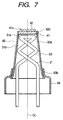
- FIG. 7 is a cross-sectional view similar to those of FIGS. 4 and 5, illustrating another embodiment of a cathode used for a cathode ray tube of the present invention.
- a cathode 60 of this embodiment the inside diameter of a cylindrical cathode sleeve 63 is progressively increasing with increasing distance from an end portion 63a within which the cathode base metal 41 is fitted and fixed toward an end 63b formed with an opening to insert a heater 31 from.
- the degree of increase in the inside diameter of the cathode sleeve 63 has the same slope as that of the heater 31.
- the smallest-diameter portion 63c is fitted with and fixed to the cathode base metal 41, and reference numeral 64 denotes a cathode support cylinder.
- FIG. 8 is a cross-sectional view of an essential part of still another embodiment of a cathode used for a cathode ray tube of the present invention.
- This embodiment is substantially similar to the cathode 40 shown in FIG. 5 except that the overall length of a cylindrical cathode sleeve 73 is as short as 4.0 mm, and the cylindrical cathode sleeve 73 is suspended within the cathode cylinder 75 by a plurality (usually three) of cathode support pieces 84 equally spaced and fixed about the circumference of the cathode sleeve 73.
- a cathode ray tube provides a good contact between the heater and the cylindrical cathode sleeve, and also reduces radiation losses of heat from the cathode sleeve, by locally reducing a diameter of a portion of the cylindrical cathode sleeve housing the coiled portion of the heater which serves as a heat-generating portion.
- the cathode ray tube according to the present invention can provide the image-forming warm-up time sufficiently short to cause practically no inconvenience after the power for the heaters is turned on again, because the heat capacity of the disk-shaped cathode base metal is made smaller than that of a cup-shaped cathode base metal, and thereby the temperature rise of the electron-emissive material layer is sped up such that the image-forming warm-up time is shortened.
Landscapes
- Electrodes For Cathode-Ray Tubes (AREA)
- Vessels, Lead-In Wires, Accessory Apparatuses For Cathode-Ray Tubes (AREA)
- Solid Thermionic Cathode (AREA)
Abstract
Description
and
Claims (4)
- A cathode ray tube comprising a vacuum envelope including a panel portion (11), a neck portion (12) and a funnel portion (13) for connecting said panel portion and said neck portion, a phosphor screen (14) formed on an inner surface of said panel portion, and an electron gun (19) housed in said neck portion and including a cathode (40) and a heater (31a),said cathode comprising:a disk-shaped cathode base metal (41) having an oxide coating (42) thereon, and a cylindrical cathode sleeve (43) housing said heater,said cylindrical cathode sleeve including a small-diameter portion (43c) having said disk-shaped cathode base metal fitted within an end thereof and housing a top portion of said heater and a large-diameter portion housing leg portions (31) of said heater, andan axial length SL (mm) of said small-diameter portion and an outside diameter DD (mm) of said disk-shaped cathode base metal satisfying the following inequation:
- A cathode ray tube according to claim 1, wherein said axial length SL (mm) of said small-diameter portion is in a range of from 1.0 mm to 4.0 mm and said outside diameter DD (mm) of said disk-shaped cathode base metal is in a range of from 1.0 mm to 2.0 mm.
- A cathode ray tube according to claim 1, wherein said disk-shaped cathode base metal is press-fitted into said small-diameter portion from said large-diameter portion and is welded to said end of said small-diameter portion.
- A cathode ray tube according to claim 1, wherein a diameter of said small-diameter portion is at least 85 % of a diameter of said large-diameter portion.
Applications Claiming Priority (2)
| Application Number | Priority Date | Filing Date | Title |
|---|---|---|---|
| JP19015499A JP2001023504A (en) | 1999-07-05 | 1999-07-05 | Cathode ray tube |
| JP19015499 | 1999-07-05 |
Publications (2)
| Publication Number | Publication Date |
|---|---|
| EP1067572A2 true EP1067572A2 (en) | 2001-01-10 |
| EP1067572A3 EP1067572A3 (en) | 2002-08-21 |
Family
ID=16253329
Family Applications (1)
| Application Number | Title | Priority Date | Filing Date |
|---|---|---|---|
| EP00114001A Withdrawn EP1067572A3 (en) | 1999-07-05 | 2000-07-04 | Cathode ray tube with indirectly heated cathode |
Country Status (5)
| Country | Link |
|---|---|
| EP (1) | EP1067572A3 (en) |
| JP (1) | JP2001023504A (en) |
| KR (1) | KR100339749B1 (en) |
| CN (1) | CN1279500A (en) |
| TW (1) | TW452818B (en) |
Cited By (1)
| Publication number | Priority date | Publication date | Assignee | Title |
|---|---|---|---|---|
| WO2005119723A1 (en) * | 2004-06-03 | 2005-12-15 | Nanobeam Limited | Charged particle gun |
Family Cites Families (11)
| Publication number | Priority date | Publication date | Assignee | Title |
|---|---|---|---|---|
| DE2654554C2 (en) * | 1976-12-02 | 1983-04-21 | Standard Elektrik Lorenz Ag, 7000 Stuttgart | Mushroom cathode for cathode ray tubes |
| JPS53145464A (en) * | 1977-05-24 | 1978-12-18 | Toshiba Corp | Cathode structure |
| JPS5412254A (en) * | 1977-06-28 | 1979-01-29 | Nec Corp | Cathode structure for cathode-ray tube |
| JPS56149741A (en) * | 1980-04-21 | 1981-11-19 | Toshiba Corp | Quick motion type cathode |
| JPS58108628A (en) * | 1981-12-21 | 1983-06-28 | Toshiba Corp | Cathode structure and manufacture thereof |
| US4554479A (en) * | 1983-12-08 | 1985-11-19 | Rca Corporation | Cathode-ray tube having a low power cathode assembly |
| US4558254A (en) * | 1984-04-30 | 1985-12-10 | Rca Corporation | Cathode-ray tube having an improved low power cathode assembly |
| JPH04259739A (en) * | 1991-02-13 | 1992-09-16 | Nec Corp | Cathode body structure for cathode-ray tube |
| KR930004222B1 (en) * | 1991-03-22 | 1993-05-21 | 주식회사 금성사 | Electron gun for crt |
| KR930007317Y1 (en) * | 1991-08-22 | 1993-10-18 | 주식회사 금성사 | Heater coil structure of electron gun for heat radiation type cathode ray tube |
| KR970009208B1 (en) * | 1993-07-26 | 1997-06-07 | Lg Electronics Inc | Cathode structure of electron gun for crt |
-
1999
- 1999-07-05 JP JP19015499A patent/JP2001023504A/en active Pending
-
2000
- 2000-06-30 TW TW089113038A patent/TW452818B/en not_active IP Right Cessation
- 2000-07-04 EP EP00114001A patent/EP1067572A3/en not_active Withdrawn
- 2000-07-04 KR KR1020000037875A patent/KR100339749B1/en not_active Expired - Fee Related
- 2000-07-05 CN CN00106386A patent/CN1279500A/en active Pending
Cited By (4)
| Publication number | Priority date | Publication date | Assignee | Title |
|---|---|---|---|---|
| WO2005119723A1 (en) * | 2004-06-03 | 2005-12-15 | Nanobeam Limited | Charged particle gun |
| GB2414856B (en) * | 2004-06-03 | 2008-11-12 | Nanobeam Ltd | Charged particle gun |
| US7855373B2 (en) | 2004-06-03 | 2010-12-21 | Nanobeam Limited | Charged particle gun |
| CN101019201B (en) * | 2004-06-03 | 2010-12-22 | 纳米束有限公司 | Charged particle gun |
Also Published As
| Publication number | Publication date |
|---|---|
| TW452818B (en) | 2001-09-01 |
| JP2001023504A (en) | 2001-01-26 |
| CN1279500A (en) | 2001-01-10 |
| KR20010015149A (en) | 2001-02-26 |
| EP1067572A3 (en) | 2002-08-21 |
| KR100339749B1 (en) | 2002-06-05 |
Similar Documents
| Publication | Publication Date | Title |
|---|---|---|
| US6246161B1 (en) | Cathode ray tube having a small-diameter neck and method of manufacture thereof | |
| US5994830A (en) | Narrow-neck CRT having a large stem pin circle | |
| US6504293B1 (en) | Cathode ray tube having an improved cathode | |
| US6191528B1 (en) | Cathode ray tube having an improved indirectly heated cathode | |
| JP3189388B2 (en) | Cathode structure of cathode ray tube | |
| EP1067572A2 (en) | Cathode ray tube with indirectly heated cathode | |
| US6614147B2 (en) | Cathode ray tube having an improved indirectly heated cathode structure | |
| US6433469B1 (en) | Cathode ray tube having an internal voltage-dividing resistor | |
| US7078851B2 (en) | Cathode ray tube | |
| JP2964939B2 (en) | Color cathode ray tube | |
| JPH0785807A (en) | Electron gun | |
| KR200164387Y1 (en) | Electron gun of cathode ray tube | |
| KR20050111600A (en) | Indirectly heated cathode and cathode ray tube having same | |
| JP2000057975A (en) | Cathode ray tube | |
| JPH0749724Y2 (en) | Electron gun for color CRT | |
| US20030011294A1 (en) | Cathode ray tube employing a cathode structure having improved gamma characteristics | |
| JPH06223732A (en) | Cathode ray tube | |
| KR19980024509A (en) | A color cathode ray tube having an improved first grid electrode | |
| JP2002216663A (en) | Electron gun structure and cathode ray tube | |
| JPH08124500A (en) | Electron gun assembly for cathode ray tube | |
| JPH07262906A (en) | Impregnated cathode structure and cathode ray tube using the same | |
| JP2003031143A (en) | Cathode ray tube | |
| JPH1069861A (en) | Electron gun | |
| JP2002279893A (en) | Method of manufacturing electron gun assembly, electron gun assembly and cathode ray tube | |
| JPH05275024A (en) | Cathode-ray tube |
Legal Events
| Date | Code | Title | Description |
|---|---|---|---|
| PUAI | Public reference made under article 153(3) epc to a published international application that has entered the european phase |
Free format text: ORIGINAL CODE: 0009012 |
|
| AK | Designated contracting states |
Kind code of ref document: A2 Designated state(s): AT BE CH CY DE DK ES FI FR GB GR IE IT LI LU MC NL PT SE |
|
| AX | Request for extension of the european patent |
Free format text: AL;LT;LV;MK;RO;SI |
|
| PUAL | Search report despatched |
Free format text: ORIGINAL CODE: 0009013 |
|
| AK | Designated contracting states |
Kind code of ref document: A3 Designated state(s): AT BE CH CY DE DK ES FI FR GB GR IE IT LI LU MC NL PT SE |
|
| AX | Request for extension of the european patent |
Free format text: AL;LT;LV;MK;RO;SI |
|
| RIC1 | Information provided on ipc code assigned before grant |
Free format text: 7H 01J 1/20 A, 7H 01J 29/04 B |
|
| 17P | Request for examination filed |
Effective date: 20021213 |
|
| AKX | Designation fees paid |
Designated state(s): DE FR GB IT |
|
| 17Q | First examination report despatched |
Effective date: 20070907 |
|
| STAA | Information on the status of an ep patent application or granted ep patent |
Free format text: STATUS: THE APPLICATION IS DEEMED TO BE WITHDRAWN |
|
| 18D | Application deemed to be withdrawn |
Effective date: 20080118 |