EP1067446A1 - Système pour le contrôle d'un satellite en attitude et procédé correspondant - Google Patents
Système pour le contrôle d'un satellite en attitude et procédé correspondant Download PDFInfo
- Publication number
- EP1067446A1 EP1067446A1 EP00401784A EP00401784A EP1067446A1 EP 1067446 A1 EP1067446 A1 EP 1067446A1 EP 00401784 A EP00401784 A EP 00401784A EP 00401784 A EP00401784 A EP 00401784A EP 1067446 A1 EP1067446 A1 EP 1067446A1
- Authority
- EP
- European Patent Office
- Prior art keywords
- satellite
- stage
- attitude
- control
- actuators
- Prior art date
- Legal status (The legal status is an assumption and is not a legal conclusion. Google has not performed a legal analysis and makes no representation as to the accuracy of the status listed.)
- Granted
Links
Images
Classifications
-
- B—PERFORMING OPERATIONS; TRANSPORTING
- B64—AIRCRAFT; AVIATION; COSMONAUTICS
- B64G—COSMONAUTICS; VEHICLES OR EQUIPMENT THEREFOR
- B64G1/00—Cosmonautic vehicles
- B64G1/22—Parts of, or equipment specially adapted for fitting in or to, cosmonautic vehicles
- B64G1/24—Guiding or controlling apparatus, e.g. for attitude control
- B64G1/28—Guiding or controlling apparatus, e.g. for attitude control using inertia or gyro effect
-
- B—PERFORMING OPERATIONS; TRANSPORTING
- B64—AIRCRAFT; AVIATION; COSMONAUTICS
- B64G—COSMONAUTICS; VEHICLES OR EQUIPMENT THEREFOR
- B64G1/00—Cosmonautic vehicles
- B64G1/22—Parts of, or equipment specially adapted for fitting in or to, cosmonautic vehicles
- B64G1/24—Guiding or controlling apparatus, e.g. for attitude control
- B64G1/244—Spacecraft control systems
-
- B—PERFORMING OPERATIONS; TRANSPORTING
- B64—AIRCRAFT; AVIATION; COSMONAUTICS
- B64G—COSMONAUTICS; VEHICLES OR EQUIPMENT THEREFOR
- B64G1/00—Cosmonautic vehicles
- B64G1/22—Parts of, or equipment specially adapted for fitting in or to, cosmonautic vehicles
- B64G1/24—Guiding or controlling apparatus, e.g. for attitude control
- B64G1/28—Guiding or controlling apparatus, e.g. for attitude control using inertia or gyro effect
- B64G1/283—Guiding or controlling apparatus, e.g. for attitude control using inertia or gyro effect using reaction wheels
Definitions
- the invention relates to a system for providing attitude control. of a satellite in orbit, this system being more particularly intended to be exploited, when great agility of the satellite is sought. It also concerns a satellite control method comprising such a system.
- the operation of a satellite in orbit in space implies that this satellite is equipped with a system to control it in attitude so that it can be determinedly oriented and stabilized, when properly oriented.
- the orientation and stabilization of a satellite can be obtained, with a relatively low energy expenditure, by action of a attitude control system causing a reaction of the satellite to a mechanism in motion inside this satellite, the energy used can plus be a renewable energy.
- a gyroscopic actuator generates rotating torques, so that obtaining a fixed torque would be preferable.
- the law of satellite guidance equipped with a gyroscopic actuator control system is therefore in general, relatively complex and leaves room for singularities which correspond to situations where the system is unable to provide torque in direction, which can result in loss of control of the satellite.
- actuators gyroscopes are used because they offer a great capacity in terms of torque, which allows rapid rotation of the satellite they equip, at price of a particularly severe specification and oversizing of the system which controls them and although they are consequently of a high cost.
- reaction wheels which have the advantage to be mechanically less complex than gyroscopic actuators and for disadvantage of producing only a much weaker torque than that which is likely to produce a gyroscopic actuator.
- the couple likely to be produced by a reaction wheel is for example of the order of 1 Nm, which is compare with a torque likely to go up to several thousand Nm for a gyroscopic actuator.
- the invention therefore provides a system for controlling a satellite in attitude.
- this system comprises a first control stage, composed of gyroscopic actuators, and a second stage of control, consisting of reaction wheels, which are respectively operated by a scheduled processing package, the first to ensure changes of attitude of the satellite and the second to ensure the accuracy and stability of the pointing from the satellite.
- the invention also provides an attitude control method for satellite comprising a first control stage, composed of gyroscopic actuators, and a second control stage, composed of reaction wheels.
- this method exploits the first stage, composed of actuators, for making changes on command attitude of the satellite and it operates the second stage, composed of reaction wheels, for pointing the satellite and stabilizing it.
- the method also exploits the stage composed of wheels of reaction to accumulate the disturbing couples which affect the satellite.
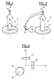
- Figures 1 and 2 correspond to two schematic representations respectively relating to a reaction wheel and to an actuator gyroscopic.
- Figure 3 shows a block diagram of an example compound floor of gyroscopic actuators for a satellite attitude control system in orbit according to the invention.
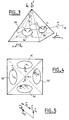
- Figure 4 is a diagram showing an example of distribution of projections in a plane of the kinetic moments created by a stage of actuators gyroscopic as illustrated in figure 3
- FIG. 5 is a vector diagram representative of the projections in a plan of the kinetic moments which are created by a stage of actuators gyroscopic, as illustrated in figure 3, and which correspond to the distribution shown in Figure 4.
- Figure 6 shows a block diagram of an example floor, composed by reaction wheels, for a satellite attitude control system in orbit according to the invention.
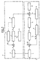
- FIG. 7 is a block diagram of an example control system attitude according to the invention.
- FIG. 1 A schematic representation of a reaction wheel 1, according to the known art, is shown in Figure 1, this wheel has a disc 2 rotated about an axis A, fixedly oriented, and this disc has a kinetic moment H which increases with the speed of rotation ⁇ imparted to it by an adjustable speed motor, not shown. Two different angular momentum values H 1 and H 2 are symbolized in the figure.
- the useful torque Tu produced by the disc 2 is an axial torque which increases with speed and which tends to rotate by reaction the structure at which the wheel 1 is mounted, this structure being that of a satellite in the application considered.
- the mass of a disc of reaction wheel on board a satellite must generally remain limited, consequently the torque obtained and the maximum angular momentum exchange do generally cannot be very high.
- the support mechanisms and wheel drive can easily be simple and robust and the control of the speed of the wheel, by action on the motor which drives it, can be achieved by implementation of effective and safe techniques, well controlled by the man of job.
- FIG. 2 A schematic representation of a gyroscopic actuator 3, according to the known art, is shown in Figure 2, such an actuator comprises a disc 4 rotated about an axis YY ', whose orientation in a fixed plane can be voluntarily modified due to the mounting of the disc 4 in a simple gimbal servo mechanism, not shown.
- the speed of rotation of the disc 4 is kept constant and results in a kinetic moment H 3 of determined constant absolute value.
- H 3 of determined constant absolute value.
- a significant transfer of energy takes place between the disc 4 and the structure where the gyroscopic actuator is mounted, when the orientation of the axis B and therefore that of the angular momentum H3 are modified. This is achieved by a tilting action which is controlled at the gimbal mechanism and which causes rotation of the axis B in a plane.
- Two orientations of the angular momentum H 3 and H ' 3 of the disc 4 are illustrated here, the orientation of the second is assumed to be obtained by tilting the axis B at right
- the number and position of the actuators of a satellite is determined with the objective of enabling it to achieve and maintain a maximum of different attitudes when it is in orbit, and to avoid that an unmodifiable attitude can be obtained.
- Figure 3 shows a schematic example of a group structure of known gyroscopic actuators, which is here assumed to be used for the constitution of a control stage by gyroscopic actuators for control of the attitude of a satellite in orbit according to the invention, it being understood that this stage may possibly be made up of gyroscopic actuators the number of which and / or the layout is or are different.
- actuators gyros are used to ensure the positioning of a satellite they equip, these actuators are distributed so that the plane in which the kinetic moment H specific to each of them is confused with that defined by one of the four side faces of a pyramid with a square base.
- the closed curve constituting the envelope where the angular momentum H of each of them is likely to move is shown on a corresponding face of the pyramid, under one of the references 3a, 3b, 3c, 3d.
- a kinetic moment h i and the corresponding output torque t i at an instant i are shown diagrammatically in FIG. 3 for the actuator whose angular moment curve is referenced 3a.
- each actuator makes it possible to rotate this satellite with respect to the axis of articulation of its own gimbal according to which tilts, on command, the disc 4 that this actuator comprises.
- This axis of rotation passes through the center of the angular momentum curve to the plane of which it is perpendicular, such as the axis referenced W for the actuator whose envelope curve is 3a.
- the change in angular momentum obtained with an actuator results in a torque which causes the satellite to rotate relative to the W axis with a rotation speed ⁇ ⁇ .
- This rotation can be considered as resulting in rotations along the three axes X, Y, Z of a fixed frame of reference with respective components of speed ⁇ ⁇ x , ⁇ ⁇ y , ⁇ ⁇ z .
- Each of these three components can be considered as obtained by combination of the components which are in the reference plane to which the component considered is perpendicular, such as the XY plane defined by the axes X and Y for the component ⁇ ⁇ z and which are due to the rotations simultaneously produced by the four gyroscopic actuators of the satellite, at this time.
- Obtaining a rotation of the satellite by a given angle by action of the gyroscopic actuators therefore results in obtaining an angular momentum resulting whose components projected in the three planes XY, XZ and YZ must be able to be obtained by vector addition of the projections of the angular moments then produced by the four actuators.
- the intervention of the gyroscopic actuators 3 of a satellite is more specifically geared towards making changes of attitude of the satellite on command and a stage of control by reaction wheels 2 is associated with the stage, formed by the gyroscopic actuators 3 in this satellite, to ensure pointing accuracy and satellite stabilization.
- gyroscopic actuators including the specifications are much less restrictive than those of the actuators known to the extent that essentially exploited to provide agility to satellite, they do not need to be very precise, since the precision of the positioning of the satellite is taken care of by the stage composed of wheels reaction. It is therefore possible to design them by favoring robustness and simplicity.
- the combination of a stage composed of gyroscopic actuators and of a stage composed of reaction wheels, within the framework of the same system of attitude control eliminates the risk of singularity likely to lead loss of control of the satellite that exists with a control system does comprising only gyroscopic actuators. It is thus possible to operate at maximum potential in angular momentum of the gyroscopic actuator stage.
- FIG. 6 A nonlimiting example of a stage composed of reaction wheels is shown schematically in Figure 6. It is made according to a known arrangement, here assumed included in the context of the invention.
- the stage presented consists of three reaction wheels 2a, 2b, 2c having their respective axes of rotation which correspond angularly to the 3 axes X, Y, Z of the fixed repository mentioned above.
- the angular momentum value of each of these wheels can be modified with precision by acting on the engine speed causing the rotation of this wheel.
- the floor reaction wheel combination allows obtaining a low value torque, finely modular and easily usable at the satellite level, to precisely finish a pointing or also attitude correction during stabilization.
- the attitude control system comprises a processing unit programmed to control the two control stages.
- This treatment set can be supervised from the ground. It acts according to a programming, recorded in an on-board storage unit and / or transmitted from the ground, which determines a profile to be respected.
- a block diagram of such processing assembly is illustrated in Figure 7, by way of non-limiting example.
- This processing set includes two sub-sets 5 and 6 taking respectively take into account the gyroscopic actuators and the reaction wheels.
- the sub-assembly 5 responsible for taking into account the gyroscopic actuators receives from the unit 7 an angular positioning instruction, known as a gimbal, referenced ⁇ in FIG. 7.
- This instruction defines here the angle of inclination to be given mechanically to each universal joint and therefore corresponds to the choice of an angle determined for the angular momentum specific to each actuator, from a reference position of mechanically determined gimbal.
- a setpoint is usually kept until the next setpoint given by the chosen profile is sent.
- the angle indication ⁇ is processed by an attitude corrector 9 in conjunction with a measured angle indication ⁇ m , supplied by a sensor 10 coupled to the stage of control 11 composed of gyroscopic actuators 3, and an estimate Cg of the gyroscopic torque produced by a unit 12.
- the corrector supplies a setpoint of engine torque C M from an angle indication which is obtained by adding the indications ⁇ and ⁇ m and the estimate Cg.
- This instruction results in a specific tilt command for the gimbal of each of the gyroscopic actuators of stage 11, it is operated by the motor which ensures the changes in orientation of the gimbal in each actuator 3.
- the setpoint in position is directly controlled by the motor which provides the universal joint with the desired orientation. In this case, it is an open loop that does not require a sensor.
- the torque produced by the gyroscopic actuator stage is taken into account by sub-assembly 5, relating to reaction wheels 2, where it is considered to be one of the disturbances which this subset ensures is taken into account.
- sub-assembly 5 relating to reaction wheels 2, where it is considered to be one of the disturbances which this subset ensures is taken into account.
- disturbances the various phenomena more particularly of external origin whose intervention is likely to modify in a parasitic way the attitude of the satellite in orbit in a way other than that imposed by the subset 5.
- a modification occurs for example when the satellite has a remote external structural element, such as a solar panel, which tends to impose an unwanted rotation to the satellite due to its drag.
- the sub-assembly 5 is also connected to the unit 7 from which it is capable of receiving specific data, according to the profile then chosen for the satellite.
- this unit 7 is assumed to be included in the sub-assembly 5 where it is connected to an attitude corrector 13. This acts on the stage 14 of reaction wheels 2 of the satellite so that these wheels dynamically change the attitude of the satellite. This attitude and this speed are a function of the torques applied to the satellite by the reaction wheels, the gyroscopic actuators and the disturbing torques which act on the satellite dynamically.
- the resulting torque C r applied to the satellite, causes a rotation of this satellite whose attitude ⁇ and speed ⁇ ⁇ are determined by a set of sensors 17, it is symbolized fictitiously in this stage under the reference 16 ,.
- the indications of attitude measurement ⁇ m and of rotation speed measurement ⁇ ⁇ m of satellite carried out by the set of sensors 17 are added to the indications provided by the unit 7 to constitute instructions for correction of position error.
- angular ⁇ and rotational speed ⁇ ⁇ which are used by the attitude corrector 13 to provide a torque setpoint Cc to the stage 14 of the satellite reaction wheels.
- This instruction results in a specific speed control for the drive motor, not shown, of each of the reaction wheels which produces the required torque by accelerating, decelerating or possibly maintaining its speed, depending on the value of torque then imposed.
- the torque likely to be produced by the reaction wheel stage is practically without effect, in the phase of attitude change under the action of gyroscopic actuators and as long as the torque produced by the stage formed by these actuators is not zero.
- the reaction wheels operate in a closed loop and they make it possible to ensure profile monitoring and the correction of position errors and speed of rotation of the satellite, these errors being notably due to imprecision relative of the torque supplied by the gyroscopic actuator stage reinjected in a loop before.
Landscapes
- Engineering & Computer Science (AREA)
- Remote Sensing (AREA)
- Chemical & Material Sciences (AREA)
- Combustion & Propulsion (AREA)
- Radar, Positioning & Navigation (AREA)
- Aviation & Aerospace Engineering (AREA)
- Automation & Control Theory (AREA)
- Control Of Position, Course, Altitude, Or Attitude Of Moving Bodies (AREA)
- Motorcycle And Bicycle Frame (AREA)
Abstract
Description
Claims (5)
- Système pour le contrôle d'un satellite en attitude caractérisé en ce qu'il comporte un premier étage de contrôle (11) composé d'actionneurs gyroscopiques et un second étage de contrôle (14) composé de roues à réaction respectivement exploités dans le cadre d'un ensemble de traitement programmé (5, 6), le premier étage pour assurer les changements d'attitude du satellite et le second pour assure la précision et la stabilité du pointage du satellite.
- Système selon la revendication 1, dans lequel le premier étage de contrôle comporte quatre actionneurs gyroscopiques (3) disposés selon une configuration pyramidale.
- Système selon l'une des revendications 1 et 2, dans lequel le second étage de contrôle (14) comporte au moins trois roues de réaction (1) dont les axes de rotation ont des orientations différentes.
- Procédé de contrôle d'attitude pour satellite équipé d'un premier étage de contrôle (11) composé d'actionneurs gyroscopiques et d'un second étage de contrôle (14) composé de roues à réaction, caractérisé en ce qu'il exploite le premier étage composé d'actionneurs pour la réalisation sur commande des changements d'attitude du satellite et en ce qu'il exploite le second étage composé de roues de réaction pour le pointage du satellite et sa stabilisation.
- Procédé, selon la revendication 4, dans lequel l'étage composé de roues de réaction est exploité pour accumuler les couples perturbateurs qui affectent le satellite.
Applications Claiming Priority (2)
| Application Number | Priority Date | Filing Date | Title |
|---|---|---|---|
| FR9908841A FR2796172B1 (fr) | 1999-07-08 | 1999-07-08 | Systeme pour le controle d'un satellite en attitude et procede corespondant |
| FR9908841 | 1999-07-08 |
Publications (2)
| Publication Number | Publication Date |
|---|---|
| EP1067446A1 true EP1067446A1 (fr) | 2001-01-10 |
| EP1067446B1 EP1067446B1 (fr) | 2007-12-12 |
Family
ID=9547861
Family Applications (1)
| Application Number | Title | Priority Date | Filing Date |
|---|---|---|---|
| EP00401784A Expired - Lifetime EP1067446B1 (fr) | 1999-07-08 | 2000-06-22 | Système pour le contrôle d'un satellite en attitude et procédé correspondant |
Country Status (4)
| Country | Link |
|---|---|
| US (1) | US6499699B1 (fr) |
| EP (1) | EP1067446B1 (fr) |
| DE (1) | DE60037366T2 (fr) |
| FR (1) | FR2796172B1 (fr) |
Families Citing this family (10)
| Publication number | Priority date | Publication date | Assignee | Title |
|---|---|---|---|---|
| FR2819597B1 (fr) * | 2001-01-15 | 2003-04-11 | Cit Alcatel | Procede de guidage d'un systeme d'actionneurs gyrospcopiques |
| US6772978B2 (en) * | 2002-02-22 | 2004-08-10 | Honeywell International Inc. | Dynamic unbalance compensation system and method |
| US6883757B2 (en) * | 2002-10-09 | 2005-04-26 | Lockheed Martin Corporation | System and method for increasing the roll offset operating range for a spacecraft |
| FR2846107B1 (fr) * | 2002-10-21 | 2005-06-24 | Cit Alcatel | Dispositif de controle d'attitude d'un satellite geostationnaire |
| US7364120B2 (en) | 2004-08-26 | 2008-04-29 | Honeywell International, Inc. | Quantized control-moment gyroscope array |
| KR100552583B1 (ko) | 2004-11-16 | 2006-02-15 | 한국과학기술원 | 특이점 문제를 개선한 제어 모멘트 자이로스코프 및 그구동 방법 |
| WO2010135421A2 (fr) * | 2009-05-19 | 2010-11-25 | University Of Florida Research Foundation, Inc. | Système de commande d'attitude pour petits satellites |
| US8014911B2 (en) * | 2009-11-03 | 2011-09-06 | Honeywell International Inc. | Methods and systems for imposing a momentum boundary while reorienting an agile vehicle with control moment gyroscopes |
| CN103439974A (zh) * | 2013-08-21 | 2013-12-11 | 南京航空航天大学 | 一种卫星姿态确定系统硬件可重构性度量方法 |
| FR3094479B1 (fr) * | 2019-03-25 | 2021-08-27 | Airbus Defence & Space Sas | Dispositif et procédé de détermination d’attitude d’un satellite équipé d’actionneurs gyroscopiques, et satellite embarquant un tel dispositif |
Citations (1)
| Publication number | Priority date | Publication date | Assignee | Title |
|---|---|---|---|---|
| EP0568209A1 (fr) * | 1992-04-28 | 1993-11-03 | Space Systems / Loral, Inc. | Contrôle d'attitude et réduction du moment cinétique d'un véhicule spatial utilisant des propulseurs à poussée réglable connectés par cardan |
Family Cites Families (7)
| Publication number | Priority date | Publication date | Assignee | Title |
|---|---|---|---|---|
| US3452948A (en) * | 1967-01-03 | 1969-07-01 | Garrett Corp | System and method for free body stabilization and orientation |
| US5826829A (en) * | 1996-07-15 | 1998-10-27 | Space Systems/Loral Inc. | Spacecraft control system with a trihedral momentum bias wheel configuration |
| US6076772A (en) * | 1997-12-15 | 2000-06-20 | Hughes Electronics Corporation | Methods for controlling spacecraft attitudes without exciting spacecraft resonances |
| US6089508A (en) * | 1998-03-02 | 2000-07-18 | Hughes Electronics Corporation | Autonomous spacecraft safing with reaction wheels |
| US6135392A (en) * | 1998-09-29 | 2000-10-24 | Hughes Electronics Corporation | Spacecraft attitude control actuator and method |
| US6113033A (en) * | 1999-02-04 | 2000-09-05 | Hughes Electronics Corporation | Combined flywheel energy storage and attitude control apparatus for spacecraft |
| US6241194B1 (en) * | 1999-06-28 | 2001-06-05 | Honeywell International Inc. | Momentum position control |
-
1999
- 1999-07-08 FR FR9908841A patent/FR2796172B1/fr not_active Expired - Fee Related
-
2000
- 2000-06-22 DE DE60037366T patent/DE60037366T2/de not_active Expired - Lifetime
- 2000-06-22 EP EP00401784A patent/EP1067446B1/fr not_active Expired - Lifetime
- 2000-06-30 US US09/607,956 patent/US6499699B1/en not_active Expired - Fee Related
Patent Citations (1)
| Publication number | Priority date | Publication date | Assignee | Title |
|---|---|---|---|---|
| EP0568209A1 (fr) * | 1992-04-28 | 1993-11-03 | Space Systems / Loral, Inc. | Contrôle d'attitude et réduction du moment cinétique d'un véhicule spatial utilisant des propulseurs à poussée réglable connectés par cardan |
Non-Patent Citations (2)
| Title |
|---|
| HARI B HABLANI: "SUN-TRACKING COMMANDS AND REACTION WHEEL SIZING WITH CONFIGURATION OPTIMIZATION", JOURNAL OF GUIDANCE AND CONTROL AND DYNAMICS,US,AIAA. NEW YORK, vol. 17, no. 4, 1 July 1994 (1994-07-01), pages 805 - 814, XP000494550, ISSN: 0731-5090 * |
| WERTZ N L: "Spacecraft Attitude Determination and Control", 1978, NL,DORDRECHT, KLUWER, PAGE(S) 200-203, XP002130913 * |
Also Published As
| Publication number | Publication date |
|---|---|
| US6499699B1 (en) | 2002-12-31 |
| EP1067446B1 (fr) | 2007-12-12 |
| FR2796172B1 (fr) | 2001-09-21 |
| FR2796172A1 (fr) | 2001-01-12 |
| DE60037366T2 (de) | 2008-12-04 |
| DE60037366D1 (de) | 2008-01-24 |
Similar Documents
| Publication | Publication Date | Title |
|---|---|---|
| EP1002716B1 (fr) | Procédé et dispositif de pilotage de l'attitude d'un satellite | |
| EP2758311B1 (fr) | Procede de controle d'attitude d'un satellite et satellite commande en attitude | |
| EP3381813B1 (fr) | Satellite comportant des moyens de propulsion electriques portes par des moyens de deplacement et des moyens de propulsion electriques additionnels d'orientation fixe | |
| EP0055720B1 (fr) | Dispositif d'orientation et de positionnement d'une charge utile | |
| EP1067446B1 (fr) | Système pour le contrôle d'un satellite en attitude et procédé correspondant | |
| EP3074309B1 (fr) | Procédé et dispositif de commande d'une phase d'acquisition du soleil par un engin spatial | |
| EP0435708A2 (fr) | Procédé de contrôle d'attitude en roulis et en lacet d'un satellite | |
| EP3201091B1 (fr) | Procédé de contrôle d'attitude d'un satellite en mode survie, satellite adapté et procédé de commande à distance d'un tel satellite | |
| WO2005045366A1 (fr) | Controle d'attitude de satellites en particulier agiles a nombre reduit de gyrodynes | |
| EP3956219B1 (fr) | Dispositif de propulsion pour aérodyne à voilure tournante et à décollage et atterrissage verticaux, et aérodyne comprenant au moins un tel dispositif de propulsion | |
| WO2016156487A1 (fr) | Procédé et dispositif de contrôle d'attitude d'un engin spatial | |
| EP4054804A1 (fr) | Articulation à trois degrés de liberté pour un robot et procédé de commande correspondant | |
| CA1267949A (fr) | Procedure de repointage rapide des satellites a pointage terrestre, et notamment des satellites geostationnaires de telecommunication a stabilisation par volant d'inertie | |
| WO2024126941A1 (fr) | Dispositif de veille optronique stabilisée par robot manipulateur | |
| FR2907616A1 (fr) | Tourelle d'orientation deux axes avec motorisation piezo electrique | |
| EP2552782B1 (fr) | Procédé de commande d'un système de contrôle d'attitude et système de contrôle d'attitude d'un véhicule spatial | |
| FR2924095A1 (fr) | Actionneur a transfert de moment cinetique pour le controle d'attitude d'un engin spatial | |
| EP1413940B1 (fr) | Dispositif de contrôle d'attitude d'un satellite géostationnaire | |
| EP1223104B1 (fr) | Procédé de guidage d'un système d'actionneurs gyroscopiques | |
| EP0796786A1 (fr) | Procédé et dispositif pour la manoeuvre rapide d'une charge utile embarquée sur une plate-forme spatiale | |
| EP2397882B1 (fr) | Dispositif de balayage rapide double étage pour système d'observation à distance | |
| EP2668100B1 (fr) | Procédé et système de pilotage d'un engin volant à propulseur arrière | |
| EP0930551A1 (fr) | Procédé de pilotage de déposé de mèches par enroulement ou au contact sur des structures de grandes dimensions et machine pour sa mise en oeuvre | |
| WO2002093283A1 (fr) | Dispositif de pilotage pour aeronef a decollage vertical | |
| FR3162042A1 (fr) | Véhicule propulsé omnidirectionnel comportant une unité de contrôle de l’orientation des propulseurs |
Legal Events
| Date | Code | Title | Description |
|---|---|---|---|
| PUAI | Public reference made under article 153(3) epc to a published international application that has entered the european phase |
Free format text: ORIGINAL CODE: 0009012 |
|
| AK | Designated contracting states |
Kind code of ref document: A1 Designated state(s): DE GB |
|
| AX | Request for extension of the european patent |
Free format text: AL;LT;LV;MK;RO;SI |
|
| 17P | Request for examination filed |
Effective date: 20010710 |
|
| AKX | Designation fees paid |
Free format text: DE GB |
|
| RAP1 | Party data changed (applicant data changed or rights of an application transferred) |
Owner name: ALCATEL LUCENT |
|
| GRAP | Despatch of communication of intention to grant a patent |
Free format text: ORIGINAL CODE: EPIDOSNIGR1 |
|
| GRAS | Grant fee paid |
Free format text: ORIGINAL CODE: EPIDOSNIGR3 |
|
| GRAA | (expected) grant |
Free format text: ORIGINAL CODE: 0009210 |
|
| AK | Designated contracting states |
Kind code of ref document: B1 Designated state(s): DE GB |
|
| REG | Reference to a national code |
Ref country code: GB Ref legal event code: FG4D Free format text: NOT ENGLISH |
|
| REF | Corresponds to: |
Ref document number: 60037366 Country of ref document: DE Date of ref document: 20080124 Kind code of ref document: P |
|
| GBT | Gb: translation of ep patent filed (gb section 77(6)(a)/1977) |
Effective date: 20080227 |
|
| PLBE | No opposition filed within time limit |
Free format text: ORIGINAL CODE: 0009261 |
|
| STAA | Information on the status of an ep patent application or granted ep patent |
Free format text: STATUS: NO OPPOSITION FILED WITHIN TIME LIMIT |
|
| 26N | No opposition filed |
Effective date: 20080915 |
|
| PGFP | Annual fee paid to national office [announced via postgrant information from national office to epo] |
Ref country code: GB Payment date: 20160526 Year of fee payment: 17 Ref country code: DE Payment date: 20160614 Year of fee payment: 17 |
|
| REG | Reference to a national code |
Ref country code: DE Ref legal event code: R119 Ref document number: 60037366 Country of ref document: DE |
|
| GBPC | Gb: european patent ceased through non-payment of renewal fee |
Effective date: 20170622 |
|
| PG25 | Lapsed in a contracting state [announced via postgrant information from national office to epo] |
Ref country code: GB Free format text: LAPSE BECAUSE OF NON-PAYMENT OF DUE FEES Effective date: 20170622 Ref country code: DE Free format text: LAPSE BECAUSE OF NON-PAYMENT OF DUE FEES Effective date: 20180103 |