EP1067003A2 - Hybrid vehicle drive apparatus - Google Patents
Hybrid vehicle drive apparatus Download PDFInfo
- Publication number
- EP1067003A2 EP1067003A2 EP00113790A EP00113790A EP1067003A2 EP 1067003 A2 EP1067003 A2 EP 1067003A2 EP 00113790 A EP00113790 A EP 00113790A EP 00113790 A EP00113790 A EP 00113790A EP 1067003 A2 EP1067003 A2 EP 1067003A2
- Authority
- EP
- European Patent Office
- Prior art keywords
- stator
- ring
- motor
- hybrid vehicle
- hold ring
- Prior art date
- Legal status (The legal status is an assumption and is not a legal conclusion. Google has not performed a legal analysis and makes no representation as to the accuracy of the status listed.)
- Granted
Links
Images


Classifications
-
- B—PERFORMING OPERATIONS; TRANSPORTING
- B60—VEHICLES IN GENERAL
- B60K—ARRANGEMENT OR MOUNTING OF PROPULSION UNITS OR OF TRANSMISSIONS IN VEHICLES; ARRANGEMENT OR MOUNTING OF PLURAL DIVERSE PRIME-MOVERS IN VEHICLES; AUXILIARY DRIVES FOR VEHICLES; INSTRUMENTATION OR DASHBOARDS FOR VEHICLES; ARRANGEMENTS IN CONNECTION WITH COOLING, AIR INTAKE, GAS EXHAUST OR FUEL SUPPLY OF PROPULSION UNITS IN VEHICLES
- B60K6/00—Arrangement or mounting of plural diverse prime-movers for mutual or common propulsion, e.g. hybrid propulsion systems comprising electric motors and internal combustion engines ; Control systems therefor, i.e. systems controlling two or more prime movers, or controlling one of these prime movers and any of the transmission, drive or drive units Informative references: mechanical gearings with secondary electric drive F16H3/72; arrangements for handling mechanical energy structurally associated with the dynamo-electric machine H02K7/00; machines comprising structurally interrelated motor and generator parts H02K51/00; dynamo-electric machines not otherwise provided for in H02K see H02K99/00
- B60K6/20—Arrangement or mounting of plural diverse prime-movers for mutual or common propulsion, e.g. hybrid propulsion systems comprising electric motors and internal combustion engines ; Control systems therefor, i.e. systems controlling two or more prime movers, or controlling one of these prime movers and any of the transmission, drive or drive units Informative references: mechanical gearings with secondary electric drive F16H3/72; arrangements for handling mechanical energy structurally associated with the dynamo-electric machine H02K7/00; machines comprising structurally interrelated motor and generator parts H02K51/00; dynamo-electric machines not otherwise provided for in H02K see H02K99/00 the prime-movers consisting of electric motors and internal combustion engines, e.g. HEVs
- B60K6/22—Arrangement or mounting of plural diverse prime-movers for mutual or common propulsion, e.g. hybrid propulsion systems comprising electric motors and internal combustion engines ; Control systems therefor, i.e. systems controlling two or more prime movers, or controlling one of these prime movers and any of the transmission, drive or drive units Informative references: mechanical gearings with secondary electric drive F16H3/72; arrangements for handling mechanical energy structurally associated with the dynamo-electric machine H02K7/00; machines comprising structurally interrelated motor and generator parts H02K51/00; dynamo-electric machines not otherwise provided for in H02K see H02K99/00 the prime-movers consisting of electric motors and internal combustion engines, e.g. HEVs characterised by apparatus, components or means specially adapted for HEVs
- B60K6/40—Arrangement or mounting of plural diverse prime-movers for mutual or common propulsion, e.g. hybrid propulsion systems comprising electric motors and internal combustion engines ; Control systems therefor, i.e. systems controlling two or more prime movers, or controlling one of these prime movers and any of the transmission, drive or drive units Informative references: mechanical gearings with secondary electric drive F16H3/72; arrangements for handling mechanical energy structurally associated with the dynamo-electric machine H02K7/00; machines comprising structurally interrelated motor and generator parts H02K51/00; dynamo-electric machines not otherwise provided for in H02K see H02K99/00 the prime-movers consisting of electric motors and internal combustion engines, e.g. HEVs characterised by apparatus, components or means specially adapted for HEVs characterised by the assembly or relative disposition of components
- B60K6/405—Housings
-
- B—PERFORMING OPERATIONS; TRANSPORTING
- B60—VEHICLES IN GENERAL
- B60K—ARRANGEMENT OR MOUNTING OF PROPULSION UNITS OR OF TRANSMISSIONS IN VEHICLES; ARRANGEMENT OR MOUNTING OF PLURAL DIVERSE PRIME-MOVERS IN VEHICLES; AUXILIARY DRIVES FOR VEHICLES; INSTRUMENTATION OR DASHBOARDS FOR VEHICLES; ARRANGEMENTS IN CONNECTION WITH COOLING, AIR INTAKE, GAS EXHAUST OR FUEL SUPPLY OF PROPULSION UNITS IN VEHICLES
- B60K6/00—Arrangement or mounting of plural diverse prime-movers for mutual or common propulsion, e.g. hybrid propulsion systems comprising electric motors and internal combustion engines ; Control systems therefor, i.e. systems controlling two or more prime movers, or controlling one of these prime movers and any of the transmission, drive or drive units Informative references: mechanical gearings with secondary electric drive F16H3/72; arrangements for handling mechanical energy structurally associated with the dynamo-electric machine H02K7/00; machines comprising structurally interrelated motor and generator parts H02K51/00; dynamo-electric machines not otherwise provided for in H02K see H02K99/00
- B60K6/20—Arrangement or mounting of plural diverse prime-movers for mutual or common propulsion, e.g. hybrid propulsion systems comprising electric motors and internal combustion engines ; Control systems therefor, i.e. systems controlling two or more prime movers, or controlling one of these prime movers and any of the transmission, drive or drive units Informative references: mechanical gearings with secondary electric drive F16H3/72; arrangements for handling mechanical energy structurally associated with the dynamo-electric machine H02K7/00; machines comprising structurally interrelated motor and generator parts H02K51/00; dynamo-electric machines not otherwise provided for in H02K see H02K99/00 the prime-movers consisting of electric motors and internal combustion engines, e.g. HEVs
- B60K6/42—Arrangement or mounting of plural diverse prime-movers for mutual or common propulsion, e.g. hybrid propulsion systems comprising electric motors and internal combustion engines ; Control systems therefor, i.e. systems controlling two or more prime movers, or controlling one of these prime movers and any of the transmission, drive or drive units Informative references: mechanical gearings with secondary electric drive F16H3/72; arrangements for handling mechanical energy structurally associated with the dynamo-electric machine H02K7/00; machines comprising structurally interrelated motor and generator parts H02K51/00; dynamo-electric machines not otherwise provided for in H02K see H02K99/00 the prime-movers consisting of electric motors and internal combustion engines, e.g. HEVs characterised by the architecture of the hybrid electric vehicle
- B60K6/48—Parallel type
- B60K6/485—Motor-assist type
-
- H—ELECTRICITY
- H02—GENERATION; CONVERSION OR DISTRIBUTION OF ELECTRIC POWER
- H02K—DYNAMO-ELECTRIC MACHINES
- H02K1/00—Details of the magnetic circuit
- H02K1/06—Details of the magnetic circuit characterised by the shape, form or construction
- H02K1/12—Stationary parts of the magnetic circuit
- H02K1/14—Stator cores with salient poles
- H02K1/146—Stator cores with salient poles consisting of a generally annular yoke with salient poles
- H02K1/148—Sectional cores
-
- H—ELECTRICITY
- H02—GENERATION; CONVERSION OR DISTRIBUTION OF ELECTRIC POWER
- H02K—DYNAMO-ELECTRIC MACHINES
- H02K3/00—Details of windings
- H02K3/46—Fastening of windings on the stator or rotor structure
- H02K3/52—Fastening salient pole windings or connections thereto
- H02K3/521—Fastening salient pole windings or connections thereto applicable to stators only
- H02K3/522—Fastening salient pole windings or connections thereto applicable to stators only for generally annular cores with salient poles
-
- H—ELECTRICITY
- H02—GENERATION; CONVERSION OR DISTRIBUTION OF ELECTRIC POWER
- H02K—DYNAMO-ELECTRIC MACHINES
- H02K5/00—Casings; Enclosures; Supports
- H02K5/04—Casings or enclosures characterised by the shape, form or construction thereof
- H02K5/22—Auxiliary parts of casings not covered by groups H02K5/06-H02K5/20, e.g. shaped to form connection boxes or terminal boxes
- H02K5/225—Terminal boxes or connection arrangements
-
- H—ELECTRICITY
- H02—GENERATION; CONVERSION OR DISTRIBUTION OF ELECTRIC POWER
- H02K—DYNAMO-ELECTRIC MACHINES
- H02K7/00—Arrangements for handling mechanical energy structurally associated with dynamo-electric machines, e.g. structural association with mechanical driving motors or auxiliary dynamo-electric machines
- H02K7/006—Structural association of a motor or generator with the drive train of a motor vehicle
-
- H—ELECTRICITY
- H02—GENERATION; CONVERSION OR DISTRIBUTION OF ELECTRIC POWER
- H02K—DYNAMO-ELECTRIC MACHINES
- H02K21/00—Synchronous motors having permanent magnets; Synchronous generators having permanent magnets
- H02K21/12—Synchronous motors having permanent magnets; Synchronous generators having permanent magnets with stationary armatures and rotating magnets
- H02K21/14—Synchronous motors having permanent magnets; Synchronous generators having permanent magnets with stationary armatures and rotating magnets with magnets rotating within the armatures
- H02K21/16—Synchronous motors having permanent magnets; Synchronous generators having permanent magnets with stationary armatures and rotating magnets with magnets rotating within the armatures having annular armature cores with salient poles
-
- H—ELECTRICITY
- H02—GENERATION; CONVERSION OR DISTRIBUTION OF ELECTRIC POWER
- H02K—DYNAMO-ELECTRIC MACHINES
- H02K2203/00—Specific aspects not provided for in the other groups of this subclass relating to the windings
- H02K2203/09—Machines characterised by wiring elements other than wires, e.g. bus rings, for connecting the winding terminations
-
- Y—GENERAL TAGGING OF NEW TECHNOLOGICAL DEVELOPMENTS; GENERAL TAGGING OF CROSS-SECTIONAL TECHNOLOGIES SPANNING OVER SEVERAL SECTIONS OF THE IPC; TECHNICAL SUBJECTS COVERED BY FORMER USPC CROSS-REFERENCE ART COLLECTIONS [XRACs] AND DIGESTS
- Y02—TECHNOLOGIES OR APPLICATIONS FOR MITIGATION OR ADAPTATION AGAINST CLIMATE CHANGE
- Y02T—CLIMATE CHANGE MITIGATION TECHNOLOGIES RELATED TO TRANSPORTATION
- Y02T10/00—Road transport of goods or passengers
- Y02T10/60—Other road transportation technologies with climate change mitigation effect
- Y02T10/62—Hybrid vehicles
-
- Y—GENERAL TAGGING OF NEW TECHNOLOGICAL DEVELOPMENTS; GENERAL TAGGING OF CROSS-SECTIONAL TECHNOLOGIES SPANNING OVER SEVERAL SECTIONS OF THE IPC; TECHNICAL SUBJECTS COVERED BY FORMER USPC CROSS-REFERENCE ART COLLECTIONS [XRACs] AND DIGESTS
- Y10—TECHNICAL SUBJECTS COVERED BY FORMER USPC
- Y10S—TECHNICAL SUBJECTS COVERED BY FORMER USPC CROSS-REFERENCE ART COLLECTIONS [XRACs] AND DIGESTS
- Y10S903/00—Hybrid electric vehicles, HEVS
- Y10S903/902—Prime movers comprising electrical and internal combustion motors
- Y10S903/903—Prime movers comprising electrical and internal combustion motors having energy storing means, e.g. battery, capacitor
- Y10S903/904—Component specially adapted for hev
- Y10S903/905—Combustion engine
-
- Y—GENERAL TAGGING OF NEW TECHNOLOGICAL DEVELOPMENTS; GENERAL TAGGING OF CROSS-SECTIONAL TECHNOLOGIES SPANNING OVER SEVERAL SECTIONS OF THE IPC; TECHNICAL SUBJECTS COVERED BY FORMER USPC CROSS-REFERENCE ART COLLECTIONS [XRACs] AND DIGESTS
- Y10—TECHNICAL SUBJECTS COVERED BY FORMER USPC
- Y10S—TECHNICAL SUBJECTS COVERED BY FORMER USPC CROSS-REFERENCE ART COLLECTIONS [XRACs] AND DIGESTS
- Y10S903/00—Hybrid electric vehicles, HEVS
- Y10S903/902—Prime movers comprising electrical and internal combustion motors
- Y10S903/903—Prime movers comprising electrical and internal combustion motors having energy storing means, e.g. battery, capacitor
- Y10S903/904—Component specially adapted for hev
- Y10S903/906—Motor or generator
-
- Y—GENERAL TAGGING OF NEW TECHNOLOGICAL DEVELOPMENTS; GENERAL TAGGING OF CROSS-SECTIONAL TECHNOLOGIES SPANNING OVER SEVERAL SECTIONS OF THE IPC; TECHNICAL SUBJECTS COVERED BY FORMER USPC CROSS-REFERENCE ART COLLECTIONS [XRACs] AND DIGESTS
- Y10—TECHNICAL SUBJECTS COVERED BY FORMER USPC
- Y10S—TECHNICAL SUBJECTS COVERED BY FORMER USPC CROSS-REFERENCE ART COLLECTIONS [XRACs] AND DIGESTS
- Y10S903/00—Hybrid electric vehicles, HEVS
- Y10S903/902—Prime movers comprising electrical and internal combustion motors
- Y10S903/903—Prime movers comprising electrical and internal combustion motors having energy storing means, e.g. battery, capacitor
- Y10S903/904—Component specially adapted for hev
- Y10S903/909—Gearing
-
- Y—GENERAL TAGGING OF NEW TECHNOLOGICAL DEVELOPMENTS; GENERAL TAGGING OF CROSS-SECTIONAL TECHNOLOGIES SPANNING OVER SEVERAL SECTIONS OF THE IPC; TECHNICAL SUBJECTS COVERED BY FORMER USPC CROSS-REFERENCE ART COLLECTIONS [XRACs] AND DIGESTS
- Y10—TECHNICAL SUBJECTS COVERED BY FORMER USPC
- Y10S—TECHNICAL SUBJECTS COVERED BY FORMER USPC CROSS-REFERENCE ART COLLECTIONS [XRACs] AND DIGESTS
- Y10S903/00—Hybrid electric vehicles, HEVS
- Y10S903/902—Prime movers comprising electrical and internal combustion motors
- Y10S903/903—Prime movers comprising electrical and internal combustion motors having energy storing means, e.g. battery, capacitor
- Y10S903/904—Component specially adapted for hev
- Y10S903/915—Specific drive or transmission adapted for hev
- Y10S903/917—Specific drive or transmission adapted for hev with transmission for changing gear ratio
-
- Y—GENERAL TAGGING OF NEW TECHNOLOGICAL DEVELOPMENTS; GENERAL TAGGING OF CROSS-SECTIONAL TECHNOLOGIES SPANNING OVER SEVERAL SECTIONS OF THE IPC; TECHNICAL SUBJECTS COVERED BY FORMER USPC CROSS-REFERENCE ART COLLECTIONS [XRACs] AND DIGESTS
- Y10—TECHNICAL SUBJECTS COVERED BY FORMER USPC
- Y10S—TECHNICAL SUBJECTS COVERED BY FORMER USPC CROSS-REFERENCE ART COLLECTIONS [XRACs] AND DIGESTS
- Y10S903/00—Hybrid electric vehicles, HEVS
- Y10S903/902—Prime movers comprising electrical and internal combustion motors
- Y10S903/903—Prime movers comprising electrical and internal combustion motors having energy storing means, e.g. battery, capacitor
- Y10S903/951—Assembly or relative location of components
-
- Y—GENERAL TAGGING OF NEW TECHNOLOGICAL DEVELOPMENTS; GENERAL TAGGING OF CROSS-SECTIONAL TECHNOLOGIES SPANNING OVER SEVERAL SECTIONS OF THE IPC; TECHNICAL SUBJECTS COVERED BY FORMER USPC CROSS-REFERENCE ART COLLECTIONS [XRACs] AND DIGESTS
- Y10—TECHNICAL SUBJECTS COVERED BY FORMER USPC
- Y10S—TECHNICAL SUBJECTS COVERED BY FORMER USPC CROSS-REFERENCE ART COLLECTIONS [XRACs] AND DIGESTS
- Y10S903/00—Hybrid electric vehicles, HEVS
- Y10S903/902—Prime movers comprising electrical and internal combustion motors
- Y10S903/903—Prime movers comprising electrical and internal combustion motors having energy storing means, e.g. battery, capacitor
- Y10S903/952—Housing details
Definitions
- the present invention relates to a hybrid vehicle drive apparatus for driving a vehicle by both or any one of a driving force of an internal combustion engine and a drive force of an alternating current motor, and more particularly to a hybrid vehicle drive apparatus in which the alternating current motor is connected to a crank shaft between the internal combustion engine and a transmission.
- a stator employed in the alternating current motor for the hybrid vehicle is generally structured such that a multiplicity of ring-like silicone steel plates each has a plurality of stator teeth protruding from an inner peripheral end portion of a ring-like stator core toward a center along a circumference are laminated so as to constitute a stator core, and each stator coil is wound around the laminated portion of each stator tooth.
- stator coil In order to improve a space factor of the stator coil wound around the stator tooth, it is desirable that the stator coil is closely wound each of the stator teeth, and it is desirable that the stator coil is independently wound around each of the stator teeth.
- stator teeth since the stator teeth are fixedly arranged adjacent to each other, it is impossible to closely wind the stator coil around each of the stator teeth with passing through a gap in each of the stator teeth, so that a high space factor can not be obtained.
- a stator core is constituted by arranging independent stator pieces corresponding to a predetermined angle (for example, corresponding to one slot) so as to form a ring shape and a stator coil is previously wound around each of the stator pieces.
- a fixing method utilizing the fact that a coefficient of thermal expansion of the aluminum is greater than a coefficient of thermal expansion of the steel. That is, an opening having an inner diameter slightly smaller than an outer peripheral size of the stator is previously formed at the aluminum motor housing, and the stator is press-fitted to the opening after the inner diameter of the opening is expanded by heating the motor housing.
- the fixing method mentioned above can not be employed.
- An object of the present invention is to provide a hybrid vehicle drive apparatus in which a stator of a motor used under a high temperature environment can be simply and securely fixed to a motor housing.
- a hybrid vehicle drive apparatus in which an alternating current motor is connected to a crank shaft between an internal combustion engine and a transmission, wherein the alternating current motor is provided with a motor housing connected between an internal combustion engine housing and a transmission housing, a stator constituted by arranging a plurality of stator pieces so as to form a ring shape, a stator hold ring having an opening portion corresponding to an outer peripheral shape of the stator and structured such that the stator is press-fitted to the opening portion, and fixing means for fixing the stator hold ring to the motor housing, and wherein a coefficient of thermal expansion of the stator substantially coincides with a coefficient of thermal expansion of the stator hold ring.
- stator hold ring and the motor housing are fixed by the suitable fixing means utilizing no thermal expansion and compression, it is possible to easily and securely fix the stator of the motor used under a high temperature environment to the motor housing.
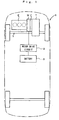
- Fig. 1 is a schematic diagram showing a hybrid vehicle V to which a hybrid vehicle drive apparatus in accordance with the present invention is applied.
- the hybrid vehicle V in accordance with the present embodiment is provided with an internal combustion engine E generating a drive force by burning a gasoline, a motor M assisting an output of the internal combustion engine E, a clutch mechanism C including a flywheel, and a transmission T transmitting a drive force generated by the internal combustion engine E and/or the motor M to a drive shaft 1.
- a transmission T a well-known manual transmission, automatic transmission and the other type of transmission can be employed.
- the motor M is a three-phase alternating current type synchronous motor and is structured such as to assist an output of the engine at a time of accelerating or the like and charge a battery 3 due to a regenerative braking function at a time of reducing a speed of a vehicle.
- the motor drive circuit 2 converts an output voltage (a direct current) of the battery 3 into an alternating current voltage so as to supply to each of the phases of the alternating current motor M.
- the engine E is controlled by engine control means (not shown).
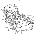
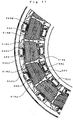
- Fig. 2 is a perspective view of the hybrid vehicle drive apparatus.
- the internal combustion engine E comprising three cylinders is constituted by an oil pan 25, a cylinder block 24 and a cylinder head 26.
- a head cover 27 is mounted to an upper portion of the cylinder head 26.
- Fig. 3 is a perspective view of only the motor M as seen from the engine side
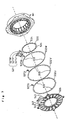
- Fig. 4 is an exploded view of the motor M
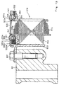
- Fig. 5 is a cross sectional view of a main portion of the motor M.
- the motor M is constituted by a stator assembly 50, a motor housing 60 receiving the stator assembly 50 and connected to the engine E, a rotor 70 directly connected to a crank shaft of the engine, a transmission side stator cover 80, a rotary sensor 10 for detecting a rotational position of the rotor 70 with respect to the stator assembly 50, a terminal holder 30, a terminal cover 90, a grommet cover 40 and the like.
- a drain hole 61 for discharging water entering within the motor M to an external portion is opened in a bottom portion of the motor housing 60.
- a drain chamber 62 for enabling the discharge while preventing the water from entering from the external portion is formed outside the bottom portion of the motor housing 60 where the drain hole 61 passes through.
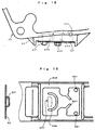
- Fig. 15 is a cross sectional view of the drain chamber 62 and Fig. 16 is a plan view of the drain chamber 62 as seen from a lower portion of the motor housing 60.
- Fig. 16 in order to easily understand the description, a state that a drain cover 63 mentioned below is taken out is shown and only a drain port 631 is shown by a broken line.
- a side elevational view of the drain cover 63 is described in a left side of Fig. 16.
- the drain cover 63 is provided with the horizontal drain port 631 formed by cutting upward a part of a plate-like member.
- the drain cover 63 mentioned above is received along an edge portion 632 formed on an inner side surface of the drain chamber 62 and is fixed so as to closely seal the inner portion of the drain chamber 62 by a bolt 622.
- Two drain holes 651 communicating with the drain hole 61 are opened in a top surface of the drain chamber 62, and a U-shaped protection wall 656 for protecting a water flooding having the same height as that of the edge portion 632 is formed so as to surround a projected area of the drain port 631 formed in the drain cover 63.
- the U-shaped protection wall 656 prevents the water from flooding into the drain chamber 62 from the drain port 631.
- a pair of protection walls 657 obliquely opposing to each other at a predetermined angle are further provided between the U-shaped protection wall 656 and the drain hole 651 in such a manner as to have the same height as that of the edge portion 632 and the protection wall 656.
- the water flooding into the motor M is discharged from the drain chamber 62 via the drain holes 61 and 651, and further discharged to the outside from the drain port 631 of the drain cover 63.
- the water flooding into the drain chamber 62 from the drain port 631 is at first prevented by the U-shaped protection wall 656 and secondly prevented by a pair of water protection walls 657. Accordingly, it is possible to discharge the water from the motor M while preventing the water from flooding into the motor M from the outside.
- the rotor 70 is, as shown in Fig. 6, constituted by a rotor main body 71, a plurality of N-pole and S-pole magnets 72 (72N and 72S) alternately arranged in an outer peripheral portion of the rotor main body 71 and a resin rotor cover 73 arranged so as to cover the magnets 72.
- a plurality of cooling fins 71a are provided on both of side surfaces of the rotor main body 71.
- Fig. 7 is an exploded view of the stator assembly 50.
- Fig. 8 is a perspective view showing an assembling method and a structure of a stator portion 501 corresponding to a main element of the stator assembly 50.
- the stator portion 501 is, as shown in Fig. 8, constituted by arranging a plurality of (18 in the present embodiment) stator pieces 510 so as to form a ring shape and press-fitting and fixing them to an opening portion of a stator hold ring 520.
- Each of the stator pieces 510 is constituted by stator core teeth 512 formed by laminating substantially T-shaped silicone steel plates, a pair of bobbin-like insulators 511 and 513 oppositely arranged in such as manner as to grip a tooth portion of each stator core teeth 512 and fitted to each other, and a stator coil 514 wound around the tooth portion of each stator core teeth 512 via the bobbin-like insulators 511 and 513.
- the stator hold ring 520 and each stator core teeth 512 are formed by the same material or materials having substantially the same coefficient of thermal expansion so that the fitting state between the both elements is not loosened due to the heat generated by the engine E during the drive operation.
- the stator core teeth 512 act as a stator core at a time of arranging the stator piece 510 so as to form a ring.
- a semicircular convex portion 512a and a semicircular recess portion 512b are respectively formed on both of end surfaces in an outer peripheral portion of the teeth 512 along a rotational axis.
- the convex portion 512a and the recess portion 512b of each of the T-shaped stator core teeth 512 arranged adjacent to each other are engaged with each other (refer to Fig. 10), thereby preventing each of the stator pieces 510 from being shifted toward the axial center.
- stator pieces 510 and the stator hold rings 520 are not proper at a time of arranging the stator pieces 510 so as to form a ring shape and press-fitting and fixing the stator pieces 510 to the opening portions of the stator hold rings 520, a magnetizing timing of each of the stator pieces 510 is shifted.
- a convex-like engaging portion 520c for restricting a relative positional relation between a line of the stator pieces (18 pieces of stator pieces, that is, the stator) arranged so as to form a ring shape and the stator hold ring 520 is formed at least one position of the end surface of the opening portion of the stator hold ring 520, as shown in Fig. 9, in such a manner as to form a longitudinal shape along an axial direction (a direction perpendicular to a paper surface).
- a recess-like engaging portion 512c engaging with the convex-like engaging portion 520c is formed on a curved surface corresponding to an outer peripheral end surface when the stator core teeth 512 are arranged so as to form a ring shape, as shown in Fig. 10, in such a manner as to form a longitudinal shape along an axial direction.
- the bobbin-like insulators 511 and 513 and the stator coil 514 of the stator piece 510 and the like are omitted.
- stator pieces 510 (the stator) previously arranged so as to form a ring shape is positioned and press-fitted to the stator hold ring 520 so that the recess-like engaging portion 512c formed on the outer peripheral end portion of any one of the stator pieces 510 is engaged with the convex-like engaging portion 520c formed on the end surface of the opening portion of the stator hold ring 520.
- both elements can be easily and accurately positioned.
- a middle point connecting bus ring 530 (a second ring-like bus) for connecting other ends 514b mentioned below of the stator coils 514 to each other
- a bus ring (a first ring-like bus) 532U for supplying a magnetizing current to all of stator coils 514U wound around U-phase stator pieces
- a bus ring 532V for supplying a magnetizing current to all of stator coils 514V wound around V-phase stator pieces
- a bus ring 532W for supplying a magnetizing current to all of stator coils 514W wound around W-phase stator pieces
- a plurality of partition walls 513a are stood on the engine side end surface of the bobbin-like insulator 513, as shown in Figs. 5 and 13.
- the bus rings 532U, 532V and 532W are respectively piled up and set at a predetermined position sectioned by the partition plate 513a.
- a current supplying terminal 537 (537U, 537V and 537W) is formed at one portion in each of the bus rings 532U, 532V and 532W, as shown in Figs. 5 and 7.
- Each of the current supplying terminals 537 is introduced to the terminal holder 30 via a bus bar 531 (531U, 531V and 531W) for supplying a drive current to each of the bus rings 532U, 532V and 532W.
- Each of the current supplying terminals 537 and each of the bus bars 531 are commonly fastened to a stator cover 535 mentioned below by a bolt 602.
- a terminal 121 of a current supply line 122 and one end of the bus bar 531 are commonly fastened by a bolt 123 within the terminal holder 30.
- An opening portion of the terminal holder 30 is covered by the terminal cover 90.
- a plurality of projection-like terminals 533U, 533V and 533W are formed in the respective inner peripheral end portions of the bus rings 532U, 532V and 532W toward a center as shown in Fig. 7, and a plurality of projection-like terminals 534 are formed in a radial direction from the outer peripheral end portion of the middle point connecting bus ring 530.
- An insulating resin is uniformly coated on an exposing surface except a main portion of each of the projection-like terminals 533 and 534 of each of the bus rings 532 and 530.
- the insulating resin material a fluorocarbon resin is preferable for the reason that a friction resistance is small and a film strength is strong in addition to a function of the insulating film.
- Each of the projection-like terminal 533U of the bus ring 532U is gripped in one end of a terminal 550 corresponding to a connecting terminal, as shown in Fig. 11.
- One end 514a of the stator coil 514U wound around the U-phase stator piece is gripped in another end of the terminal 550. Accordingly, one end 514a of the stator coil 514U wound around each of the U-phase stator pieces arranged so as to be two pieces apart from each other is commonly connected to the adjacent one end 514a thereof via the bus ring 532U.
- One end 514a of the stator coil 514V wound around each of the V-phase stator pieces is commonly connected to the adjacent one end 514a thereof via the bus ring 532V (and the terminal 550).
- One end 514a of the stator coil 514W wound around each of the W-phase stator pieces is commonly connected to the adjacent one end 514a thereof via the bus ring 532W (and the terminal 550).
- each of the projection-like terminal 534 of the middle point connecting bus ring 530 is gripped in one end of the terminal 550, in the same manner as shown in Fig. 11.
- Another end 514b of the stator coil wound around each phase of stator pieces is gripped in another end of the terminal 550.
- other ends 514b of the stator coil 514 wound around all of the stator pieces are commonly connected to each other via the bus ring 530 (and the terminal 550). That is, the bus ring 530 corresponds to a neutral point of a star connection.
- the stator is constituted by arranging the stator pieces 510 so as to form a ring, the stator coils 514 wound around the respective stator pieces 510 are respectively independent from each other, and the stator coils wound around the same-phase stator piece are connected to each other by the first bus ring 532. Accordingly, each of the stator pieces 510 can be singly treated including the stator coil 514, and a treating performance and a productivity for completely assembling the stator can be improved.
- the bus ring 532 corresponding to the current supply line to each of the phases is arranged outside and the second bus ring corresponding to the neutral point of each of the phases is arranged inside, the current supply line and the neutral point do not cross to each other and it is easy to arrange the wiring.
- stator cover 535 When the connection of the stator coil is completed as mentioned above, the coil is covered by the stator cover 535 and screwed to the stator assembly 50.
- the stator assembly 50 is screwed to the motor housing 60 by the bolt 601 as shown in Fig. 5.
- the stator and the stator hold ring 520 fitted by the press-fit have substantially the same coefficient of thermal expansion. Accordingly, even when the motor is heated due to the heat generated by the internal combustion engine during the drive of the vehicle, no looseness is generated in the connection portion between the stator and the stator hold ring. Further, since the stator hold ring 520 and the motor housing 60 are screwed and fixed to each other, it is possible to easily and securely fix the stator of the motor used under a high temperature environment to the housing 60.
- a plurality of first long holes 541 arranged along a circumferential direction, a plurality of round holes 542 arranged along a circumferential direction inside the first long hole and a plurality of second long holes 543 arranged along a circumferential direction inside the round hole are provided on the stator cover 535 in this order from the outer peripheral portion, as shown in Fig. 7.
- Fig. 12 is a view showing a relative positional relation between each of the long holes 541 and 543 and the round holes 542 on the stator cover 535 and the stator piece 510.
- the connecting portions between the terminal 550 and the projection-like terminal 533 of each of the bus rings 532 and stator coil one end 514a are exposed from the first long hole 541, and the connecting portions between the terminal 550 and the projection-like terminal 534 of each of the bus rings 530 and stator coil another end 514b are exposed from the second long hole 543.
- a seal agent 201 is charged into the stator from each of the long holes 541 and 543 and each of the connected portion (the gripped portion) is sealed.
- a thermosetting silicone resin can be employed for the seal agent 201, and the seal agent 201 is hardened by being heated in an electric furnace or the like after being charged.
- projections 241 and 242 are respectively stood from back surfaces of both end portions along a circumferential direction of the respective long holes 541 and 543 of the stator cover 535. Accordingly, the seal agent 201 charged from each of the long holes 541 and 543 is prevented from being flowed out in a circumferential direction by each of the projections 241 and 242. The seal agent is prevented from being flowed out in a radial direction and toward the center by a plurality of partition plates 513a stood from the engine side end surface of the insulator 513 and the end surface of the laminated bus ring 532, as shown in Fig. 13.
- the partition plate 513a stood from the bobbin-like insulator 513 is utilized as a flow stopper for the seal agent 201, it is possible to efficiently prevent the seal agent 201 from being flowed out without increasing the number of parts.
- the invention provides a hybrid vehicle drive apparatus in which a stator of a motor used under a high temperature environment can be simply and securely fixed to a motor housing.
- a hybrid vehicle drive apparatus in which an alternating current motor (M) is connected to a crank shaft (1) between an internal combustion engine (E) and a transmission (T), the alternating current motor is provided with a motor housing (60) connected to each of an internal combustion engine and a transmission, a stator constituted by arranging a plurality of stator pieces (510) so as to form a ring shape, a stator hold ring (520) having an opening portion corresponding to an outer peripheral shape of the stator and structured such that the stator is press-fitted to the opening portion, and the stator hold ring (520) is fixed to the motor housing (60).
- a coefficient of thermal expansion of the stator substantially coincides with a coefficient of thermal expansion of the stator hold ring (520).
Abstract
Description
- The present invention relates to a hybrid vehicle drive apparatus for driving a vehicle by both or any one of a driving force of an internal combustion engine and a drive force of an alternating current motor, and more particularly to a hybrid vehicle drive apparatus in which the alternating current motor is connected to a crank shaft between the internal combustion engine and a transmission.
- As a drive system for a hybrid vehicle, a system for driving a vehicle by both or any one of a drive force of an internal combustion engine and a drive force of an alternating current motor has been disclosed in Japanese Patent Application Laid-Open (JP-A) No. 9-156388. A stator employed in the alternating current motor for the hybrid vehicle is generally structured such that a multiplicity of ring-like silicone steel plates each has a plurality of stator teeth protruding from an inner peripheral end portion of a ring-like stator core toward a center along a circumference are laminated so as to constitute a stator core, and each stator coil is wound around the laminated portion of each stator tooth.
- In order to improve a space factor of the stator coil wound around the stator tooth, it is desirable that the stator coil is closely wound each of the stator teeth, and it is desirable that the stator coil is independently wound around each of the stator teeth. However, in the conventional stator shape, since the stator teeth are fixedly arranged adjacent to each other, it is impossible to closely wind the stator coil around each of the stator teeth with passing through a gap in each of the stator teeth, so that a high space factor can not be obtained.
- In order to solve the problem mentioned above, there can be considered a structure in which a stator core is constituted by arranging independent stator pieces corresponding to a predetermined angle (for example, corresponding to one slot) so as to form a ring shape and a stator coil is previously wound around each of the stator pieces.
- In general, in the case of fixing a steel stator to an aluminum motor housing, there is employed a fixing method utilizing the fact that a coefficient of thermal expansion of the aluminum is greater than a coefficient of thermal expansion of the steel. That is, an opening having an inner diameter slightly smaller than an outer peripheral size of the stator is previously formed at the aluminum motor housing, and the stator is press-fitted to the opening after the inner diameter of the opening is expanded by heating the motor housing.
- However, in the structure in which the alternating current motor is arranged between the internal combustion engine and the transmission so as to be connected to the crank shaft as in the hybrid vehicle drive apparatus mentioned above, since the aluminum housing is heated in the same manner as the case of fixing due to the heat generated by the internal combustion engine during a driving operation of the vehicle and a fitting state between both elements is loosened, the fixing method mentioned above can not be employed.
- An object of the present invention is to provide a hybrid vehicle drive apparatus in which a stator of a motor used under a high temperature environment can be simply and securely fixed to a motor housing.
- In order to achieve the object mentioned above, in accordance with the present invention, there is provided a hybrid vehicle drive apparatus in which an alternating current motor is connected to a crank shaft between an internal combustion engine and a transmission, wherein the alternating current motor is provided with a motor housing connected between an internal combustion engine housing and a transmission housing, a stator constituted by arranging a plurality of stator pieces so as to form a ring shape, a stator hold ring having an opening portion corresponding to an outer peripheral shape of the stator and structured such that the stator is press-fitted to the opening portion, and fixing means for fixing the stator hold ring to the motor housing, and wherein a coefficient of thermal expansion of the stator substantially coincides with a coefficient of thermal expansion of the stator hold ring.
- In accordance with the feature mentioned above, since the coefficients of thermal expansion of the stator and the stator hold ring substantially coincide with each other, a looseness is not generated in the connecting portion between the stator and the stator hold ring even when the motor is heated due to the heat generated by the internal combustion engine during the driving operation of the vehicle. Since the stator hold ring and the motor housing are fixed by the suitable fixing means utilizing no thermal expansion and compression, it is possible to easily and securely fix the stator of the motor used under a high temperature environment to the motor housing.
-
- Fig. 1 is a schematic diagram showing a hybrid vehicle V to which a hybrid vehicle drive apparatus in accordance with the present invention is applied;
- Fig. 2 is a perspective view of a hybrid vehicle drive apparatus;
- Fig. 3 is a perspective view of only a motor M as seen from an engine side;
- Fig. 4 is an exploded view of the motor M;
- Fig. 5 is a cross sectional view of a main portion of the motor M;
- Fig. 6 is a perspective view showing a structure of a rotor;
- Fig. 7 is an exploded view of a stator assembly;
- Fig. 8 is a perspective view showing an assembling method and a structure of a stator portion;
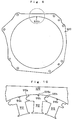
- Fig. 9 is a plan view of a stator hold ring;
- Fig. 10 is a view showing a method of positioning stator pieces to the stator hold ring;
- Fig. 11 is a plan view of the stator assembly;
- Fig. 12 is a view showing a method of connecting stator coils to a bus ring;
- Fig. 13 is a cross sectional view of a main portion of the stator assembly;
- Fig. 14 is a partly broken plan view of the stator assembly;
- Fig. 15 is a cross sectional view of a drain chamber; and
- Fig. 16 is a plan view of an inner portion of the drain chamber.
-
- Fig. 1 is a schematic diagram showing a hybrid vehicle V to which a hybrid vehicle drive apparatus in accordance with the present invention is applied.
- The hybrid vehicle V in accordance with the present embodiment is provided with an internal combustion engine E generating a drive force by burning a gasoline, a motor M assisting an output of the internal combustion engine E, a clutch mechanism C including a flywheel, and a transmission T transmitting a drive force generated by the internal combustion engine E and/or the motor M to a
drive shaft 1. As the transmission T, a well-known manual transmission, automatic transmission and the other type of transmission can be employed. - The motor M is a three-phase alternating current type synchronous motor and is structured such as to assist an output of the engine at a time of accelerating or the like and charge a
battery 3 due to a regenerative braking function at a time of reducing a speed of a vehicle. Themotor drive circuit 2 converts an output voltage (a direct current) of thebattery 3 into an alternating current voltage so as to supply to each of the phases of the alternating current motor M. The engine E is controlled by engine control means (not shown). - Fig. 2 is a perspective view of the hybrid vehicle drive apparatus. The internal combustion engine E comprising three cylinders is constituted by an
oil pan 25, acylinder block 24 and acylinder head 26. Ahead cover 27 is mounted to an upper portion of thecylinder head 26. - Fig. 3 is a perspective view of only the motor M as seen from the engine side, Fig. 4 is an exploded view of the motor M and Fig. 5 is a cross sectional view of a main portion of the motor M.
- The motor M is constituted by a
stator assembly 50, amotor housing 60 receiving thestator assembly 50 and connected to the engine E, arotor 70 directly connected to a crank shaft of the engine, a transmissionside stator cover 80, arotary sensor 10 for detecting a rotational position of therotor 70 with respect to thestator assembly 50, aterminal holder 30, aterminal cover 90, agrommet cover 40 and the like. - A
drain hole 61 for discharging water entering within the motor M to an external portion is opened in a bottom portion of themotor housing 60. Adrain chamber 62 for enabling the discharge while preventing the water from entering from the external portion is formed outside the bottom portion of themotor housing 60 where thedrain hole 61 passes through. - Fig. 15 is a cross sectional view of the
drain chamber 62 and Fig. 16 is a plan view of thedrain chamber 62 as seen from a lower portion of themotor housing 60. In Fig. 16, in order to easily understand the description, a state that adrain cover 63 mentioned below is taken out is shown and only adrain port 631 is shown by a broken line. A side elevational view of thedrain cover 63 is described in a left side of Fig. 16. - The
drain cover 63 is provided with thehorizontal drain port 631 formed by cutting upward a part of a plate-like member. Thedrain cover 63 mentioned above is received along anedge portion 632 formed on an inner side surface of thedrain chamber 62 and is fixed so as to closely seal the inner portion of thedrain chamber 62 by abolt 622. - Two
drain holes 651 communicating with thedrain hole 61 are opened in a top surface of thedrain chamber 62, and a U-shapedprotection wall 656 for protecting a water flooding having the same height as that of theedge portion 632 is formed so as to surround a projected area of thedrain port 631 formed in thedrain cover 63. The U-shapedprotection wall 656 prevents the water from flooding into thedrain chamber 62 from thedrain port 631. A pair ofprotection walls 657 obliquely opposing to each other at a predetermined angle are further provided between the U-shapedprotection wall 656 and thedrain hole 651 in such a manner as to have the same height as that of theedge portion 632 and theprotection wall 656. - In accordance with the
drain chamber 62 having the structure mentioned above, the water flooding into the motor M is discharged from thedrain chamber 62 via thedrain holes drain port 631 of thedrain cover 63. On the contrary, the water flooding into thedrain chamber 62 from thedrain port 631 is at first prevented by the U-shapedprotection wall 656 and secondly prevented by a pair ofwater protection walls 657. Accordingly, it is possible to discharge the water from the motor M while preventing the water from flooding into the motor M from the outside. - The
rotor 70 is, as shown in Fig. 6, constituted by a rotormain body 71, a plurality of N-pole and S-pole magnets 72 (72N and 72S) alternately arranged in an outer peripheral portion of the rotormain body 71 and aresin rotor cover 73 arranged so as to cover themagnets 72. A plurality ofcooling fins 71a are provided on both of side surfaces of the rotormain body 71. - Fig. 7 is an exploded view of the
stator assembly 50. Fig. 8 is a perspective view showing an assembling method and a structure of astator portion 501 corresponding to a main element of thestator assembly 50. - The
stator portion 501 is, as shown in Fig. 8, constituted by arranging a plurality of (18 in the present embodiment)stator pieces 510 so as to form a ring shape and press-fitting and fixing them to an opening portion of astator hold ring 520. - Each of the
stator pieces 510 is constituted bystator core teeth 512 formed by laminating substantially T-shaped silicone steel plates, a pair of bobbin-like insulators stator core teeth 512 and fitted to each other, and astator coil 514 wound around the tooth portion of eachstator core teeth 512 via the bobbin-like insulators ring 520 and eachstator core teeth 512 are formed by the same material or materials having substantially the same coefficient of thermal expansion so that the fitting state between the both elements is not loosened due to the heat generated by the engine E during the drive operation. - The
stator core teeth 512 act as a stator core at a time of arranging thestator piece 510 so as to form a ring. Asemicircular convex portion 512a and asemicircular recess portion 512b are respectively formed on both of end surfaces in an outer peripheral portion of theteeth 512 along a rotational axis. Theconvex portion 512a and therecess portion 512b of each of the T-shapedstator core teeth 512 arranged adjacent to each other are engaged with each other (refer to Fig. 10), thereby preventing each of thestator pieces 510 from being shifted toward the axial center. - If a relative positional relation between the
stator pieces 510 and thestator hold rings 520 is not proper at a time of arranging thestator pieces 510 so as to form a ring shape and press-fitting and fixing thestator pieces 510 to the opening portions of thestator hold rings 520, a magnetizing timing of each of thestator pieces 510 is shifted. In accordance with the present embodiment, a convex-likeengaging portion 520c for restricting a relative positional relation between a line of the stator pieces (18 pieces of stator pieces, that is, the stator) arranged so as to form a ring shape and thestator hold ring 520 is formed at least one position of the end surface of the opening portion of the stator holdring 520, as shown in Fig. 9, in such a manner as to form a longitudinal shape along an axial direction (a direction perpendicular to a paper surface). - A recess-like
engaging portion 512c engaging with the convex-likeengaging portion 520c is formed on a curved surface corresponding to an outer peripheral end surface when thestator core teeth 512 are arranged so as to form a ring shape, as shown in Fig. 10, in such a manner as to form a longitudinal shape along an axial direction. In Fig. 10, in order to easily understand the description, the bobbin-like insulators stator coil 514 of thestator piece 510 and the like are omitted. - The stator pieces 510 (the stator) previously arranged so as to form a ring shape is positioned and press-fitted to the
stator hold ring 520 so that the recess-likeengaging portion 512c formed on the outer peripheral end portion of any one of thestator pieces 510 is engaged with the convex-likeengaging portion 520c formed on the end surface of the opening portion of thestator hold ring 520. - In accordance with the present embodiment, since the engaging means 512c and 520c engaging with each other are provided in both of the stator side and the
stator hold ring 520, both elements can be easily and accurately positioned. - When the press-fit of the
stator pieces 510 to thestator hold ring 520 is completed and thestator portion 501 is completely assembled, a middle point connecting bus ring 530 (a second ring-like bus) for connecting other ends 514b mentioned below of the stator coils 514 to each other, a bus ring (a first ring-like bus) 532U for supplying a magnetizing current to all of stator coils 514U wound around U-phase stator pieces, abus ring 532V for supplying a magnetizing current to all of stator coils 514V wound around V-phase stator pieces, and abus ring 532W for supplying a magnetizing current to all of stator coils 514W wound around W-phase stator pieces, as shown in Fig. 7, are set to the end surface of the bobbin-like insulator 513 as shown in Fig. 13. - A plurality of
partition walls 513a are stood on the engine side end surface of the bobbin-like insulator 513, as shown in Figs. 5 and 13. The bus rings 532U, 532V and 532W are respectively piled up and set at a predetermined position sectioned by thepartition plate 513a. A current supplying terminal 537 (537U, 537V and 537W) is formed at one portion in each of the bus rings 532U, 532V and 532W, as shown in Figs. 5 and 7. Each of the current supplyingterminals 537 is introduced to theterminal holder 30 via a bus bar 531 (531U, 531V and 531W) for supplying a drive current to each of the bus rings 532U, 532V and 532W. Each of the current supplyingterminals 537 and each of the bus bars 531 are commonly fastened to astator cover 535 mentioned below by abolt 602. - A
terminal 121 of acurrent supply line 122 and one end of thebus bar 531 are commonly fastened by abolt 123 within theterminal holder 30. An opening portion of theterminal holder 30 is covered by theterminal cover 90. - A plurality of projection-
like terminals 533U, 533V and 533W are formed in the respective inner peripheral end portions of the bus rings 532U, 532V and 532W toward a center as shown in Fig. 7, and a plurality of projection-like terminals 534 are formed in a radial direction from the outer peripheral end portion of the middle point connectingbus ring 530. An insulating resin is uniformly coated on an exposing surface except a main portion of each of the projection-like terminals - Each of the projection-like terminal 533U of the
bus ring 532U is gripped in one end of a terminal 550 corresponding to a connecting terminal, as shown in Fig. 11. One end 514a of the stator coil 514U wound around the U-phase stator piece is gripped in another end of the terminal 550. Accordingly, one end 514a of the stator coil 514U wound around each of the U-phase stator pieces arranged so as to be two pieces apart from each other is commonly connected to the adjacent one end 514a thereof via thebus ring 532U. - One end 514a of the stator coil 514V wound around each of the V-phase stator pieces is commonly connected to the adjacent one end 514a thereof via the
bus ring 532V (and the terminal 550). One end 514a of the stator coil 514W wound around each of the W-phase stator pieces is commonly connected to the adjacent one end 514a thereof via thebus ring 532W (and the terminal 550). - On the contrary, each of the projection-
like terminal 534 of the middle point connectingbus ring 530 is gripped in one end of the terminal 550, in the same manner as shown in Fig. 11. Another end 514b of the stator coil wound around each phase of stator pieces is gripped in another end of the terminal 550. Accordingly, other ends 514b of thestator coil 514 wound around all of the stator pieces are commonly connected to each other via the bus ring 530 (and the terminal 550). That is, thebus ring 530 corresponds to a neutral point of a star connection. - As mentioned above, in accordance with the present embodiment, the stator is constituted by arranging the
stator pieces 510 so as to form a ring, the stator coils 514 wound around therespective stator pieces 510 are respectively independent from each other, and the stator coils wound around the same-phase stator piece are connected to each other by thefirst bus ring 532. Accordingly, each of thestator pieces 510 can be singly treated including thestator coil 514, and a treating performance and a productivity for completely assembling the stator can be improved. - Further, in accordance with the present embodiment, since the
bus ring 532 corresponding to the current supply line to each of the phases is arranged outside and the second bus ring corresponding to the neutral point of each of the phases is arranged inside, the current supply line and the neutral point do not cross to each other and it is easy to arrange the wiring. - When the connection of the stator coil is completed as mentioned above, the coil is covered by the
stator cover 535 and screwed to thestator assembly 50. Thestator assembly 50 is screwed to themotor housing 60 by thebolt 601 as shown in Fig. 5. - As mentioned above, in accordance with the present embodiment, the stator and the
stator hold ring 520 fitted by the press-fit have substantially the same coefficient of thermal expansion. Accordingly, even when the motor is heated due to the heat generated by the internal combustion engine during the drive of the vehicle, no looseness is generated in the connection portion between the stator and the stator hold ring. Further, since thestator hold ring 520 and themotor housing 60 are screwed and fixed to each other, it is possible to easily and securely fix the stator of the motor used under a high temperature environment to thehousing 60. - A plurality of first
long holes 541 arranged along a circumferential direction, a plurality ofround holes 542 arranged along a circumferential direction inside the first long hole and a plurality of secondlong holes 543 arranged along a circumferential direction inside the round hole are provided on thestator cover 535 in this order from the outer peripheral portion, as shown in Fig. 7. - Fig. 12 is a view showing a relative positional relation between each of the
long holes stator cover 535 and thestator piece 510. The connecting portions between the terminal 550 and the projection-like terminal 533 of each of the bus rings 532 and stator coil one end 514a are exposed from the firstlong hole 541, and the connecting portions between the terminal 550 and the projection-like terminal 534 of each of the bus rings 530 and stator coil another end 514b are exposed from the secondlong hole 543. - In accordance with the present embodiment, as shown in a cross sectional view in Fig. 13 and a partly broken plan view in Fig. 14, a
seal agent 201 is charged into the stator from each of thelong holes seal agent 201, and theseal agent 201 is hardened by being heated in an electric furnace or the like after being charged. - In accordance with the present embodiment, as shown in Fig. 12,
projections long holes stator cover 535. Accordingly, theseal agent 201 charged from each of thelong holes projections partition plates 513a stood from the engine side end surface of theinsulator 513 and the end surface of thelaminated bus ring 532, as shown in Fig. 13. - In accordance with the present invention, since the
partition plate 513a stood from the bobbin-like insulator 513 is utilized as a flow stopper for theseal agent 201, it is possible to efficiently prevent theseal agent 201 from being flowed out without increasing the number of parts. - In accordance with the present invention, the following effects can be achieved.
- (1) Since the coefficients of thermal expansion of the stator and the stator hold ring substantially coincide with each other, a looseness is not generated in the connecting portion between the stator and the stator hold ring even when the motor is heated due to the heat generated by the internal combustion engine during the driving operation of the vehicle. Since the stator hold ring and the motor housing are fixed by the suitable fixing means utilizing no thermal expansion and compression, it is possible to easily and securely fix the stator of the motor used under a high temperature environment to the housing.
- (2) Since the engaging means engaging with each other are provided in both of the stator piece and the stator hold ring, it is possible to easily and accurately position both of the elements.
-
- The invention provides a hybrid vehicle drive apparatus in which a stator of a motor used under a high temperature environment can be simply and securely fixed to a motor housing. In a hybrid vehicle drive apparatus in which an alternating current motor (M) is connected to a crank shaft (1) between an internal combustion engine (E) and a transmission (T), the alternating current motor is provided with a motor housing (60) connected to each of an internal combustion engine and a transmission, a stator constituted by arranging a plurality of stator pieces (510) so as to form a ring shape, a stator hold ring (520) having an opening portion corresponding to an outer peripheral shape of the stator and structured such that the stator is press-fitted to the opening portion, and the stator hold ring (520) is fixed to the motor housing (60). A coefficient of thermal expansion of the stator substantially coincides with a coefficient of thermal expansion of the stator hold ring (520).
Claims (2)
- A hybrid vehicle drive apparatus in which an alternating current motor (M) is connected to a crank shaft (1) between an internal combustion engine (E) and a transmission (T),
wherein said alternating current motor (M) comprises:a motor housing (60) connected between the internal combustion engine (E) and the transmission (T);a stator (501) constituted by arranging a plurality of stator pieces (510) so as to form a ring shape;a stator hold ring (520) having an opening portion corresponding to an outer peripheral shape of said stator and structured such that said stator is press-fitted to said opening portion; andfixing means (601) for fixing said stator hold ring (520) to said motor housing (60), and
wherein a coefficient of thermal expansion of said stator substantially coincides with a coefficient of thermal expansion of said stator hold ring. - A hybrid vehicle drive apparatus according to claim 1, wherein each of said stator pieces (510) is provided with one of recess-shaped and convex-shaped engaging means (512c) on a surface constituting an outer peripheral end surface when being arranged so as to form a ring shape, and said stator hold ring (512c) is provided with another of said recess-shaped and convex-shaped engaging means on at least one of said opening portion end surfaces, and
wherein said ring-like arranged stator pieces are positioned in said opening portion of said stator hold ring so that one of said engaging means formed on any outer peripheral end surface is engaged with another of the engaging means formed in said stator hold ring.
Applications Claiming Priority (2)
| Application Number | Priority Date | Filing Date | Title |
|---|---|---|---|
| JP19109199 | 1999-07-05 | ||
| JP19109199A JP3666727B2 (en) | 1999-07-05 | 1999-07-05 | Hybrid vehicle drive device |
Publications (3)
| Publication Number | Publication Date |
|---|---|
| EP1067003A2 true EP1067003A2 (en) | 2001-01-10 |
| EP1067003A3 EP1067003A3 (en) | 2003-10-29 |
| EP1067003B1 EP1067003B1 (en) | 2006-06-21 |
Family
ID=16268714
Family Applications (1)
| Application Number | Title | Priority Date | Filing Date |
|---|---|---|---|
| EP00113790A Expired - Lifetime EP1067003B1 (en) | 1999-07-05 | 2000-06-29 | Hybrid vehicle drive apparatus |
Country Status (4)
| Country | Link |
|---|---|
| US (1) | US6470984B1 (en) |
| EP (1) | EP1067003B1 (en) |
| JP (1) | JP3666727B2 (en) |
| DE (1) | DE60028873T2 (en) |
Cited By (8)
| Publication number | Priority date | Publication date | Assignee | Title |
|---|---|---|---|---|
| WO2003021747A1 (en) * | 2001-09-03 | 2003-03-13 | Honda Giken Kogyo Kabushiki Kaisha | Wiring structure of hybrid vehicle motor |
| US7074157B2 (en) * | 2003-07-04 | 2006-07-11 | Honda Motor Co., Ltd. | Control apparatus for hybrid vehicle |
| WO2009153148A1 (en) | 2008-06-16 | 2009-12-23 | Zf Friedrichshafen Ag | Electric machine comprising a stator support for a hybrid drive train |
| US8604654B2 (en) | 2010-03-17 | 2013-12-10 | Zf Friedrichshafen Ag | Drive unit for a motor vehicle with an electric machine |
| EP2874277A3 (en) * | 2013-11-15 | 2016-06-15 | Aisin Seiki Kabushiki Kaisha | Modular electric machine |
| EP2234244A3 (en) * | 2009-03-27 | 2016-11-30 | Aisin Seiki Kabushiki Kaisha | Stator of electrical machine |
| FR3058282A1 (en) * | 2016-11-03 | 2018-05-04 | Valeo Equipements Electriques Moteur | ROTATING ELECTRIC MACHINE STATOR WITH COIL CONTROL WINDING COILS |
| FR3082580A1 (en) * | 2018-06-15 | 2019-12-20 | Renault S.A.S | CRANKCASE ELEMENT FOR A FLYWHEEL OF A MOTOR VEHICLE |
Families Citing this family (22)
| Publication number | Priority date | Publication date | Assignee | Title |
|---|---|---|---|---|
| FR2819117B1 (en) * | 2000-12-21 | 2004-10-29 | Valeo Equip Electr Moteur | ALTERNATOR WITH CONDUCTIVE ELEMENTS FOR A MOTOR VEHICLE |
| JP2002199644A (en) * | 2000-12-28 | 2002-07-12 | Aisin Aw Co Ltd | Three-phase motor |
| DE60226272T2 (en) | 2001-12-26 | 2009-05-20 | Toyota Jidosha Kabushiki Kaisha, Toyota-shi | DRIVE DEVICE OF A HYBRID VEHICLE |
| US6914357B2 (en) * | 2002-06-10 | 2005-07-05 | Visteon Global Technologies, Inc. | Electric machine with integrated power electronics |
| JP2004153891A (en) * | 2002-10-29 | 2004-05-27 | Mitsubishi Electric Corp | Rotary electric machine |
| SE524541C2 (en) * | 2002-11-18 | 2004-08-24 | Uppsala Power Man Consultants | Power storage systems and vehicles fitted with such |
| US7586225B2 (en) * | 2004-03-22 | 2009-09-08 | Gm Global Technology Operations, Inc. | Hybrid transmission motor module with integral wire connections |
| CN1738155B (en) * | 2004-03-22 | 2012-05-23 | 通用汽车公司 | Hybrid transmission motor module with integral wire connector |
| JP4483480B2 (en) * | 2004-08-27 | 2010-06-16 | アイシン精機株式会社 | Stator and motor |
| US7342334B2 (en) * | 2004-10-29 | 2008-03-11 | Emerson Electric Co. | Insulated stator with wire routing element |
| JP5176283B2 (en) * | 2006-03-30 | 2013-04-03 | 日産自動車株式会社 | Rotating electrical machine bus bar insulation structure |
| JP4907300B2 (en) * | 2006-11-06 | 2012-03-28 | 富士重工業株式会社 | Hybrid vehicle motor rotor |
| JP5499899B2 (en) | 2010-05-20 | 2014-05-21 | アイシン精機株式会社 | Method for manufacturing retaining ring of rotating electric machine |
| CN102893498A (en) | 2010-06-02 | 2013-01-23 | 爱信精机株式会社 | Electrical rotary machine |
| JP2011254623A (en) | 2010-06-02 | 2011-12-15 | Aisin Seiki Co Ltd | Rotary electric machine and stator of rotary electric machine |
| JP5247848B2 (en) * | 2011-03-31 | 2013-07-24 | 株式会社小松製作所 | Construction machinery |
| JP6221476B2 (en) * | 2013-08-01 | 2017-11-01 | 日産自動車株式会社 | Stator fixing structure of rotating electric machine |
| US20160137047A1 (en) * | 2014-11-17 | 2016-05-19 | Lg Electronics Inc. | Driving apparatus of vehicle |
| US11336145B2 (en) * | 2017-03-31 | 2022-05-17 | Nidec Corporation | Motor |
| JP7310531B2 (en) * | 2019-10-16 | 2023-07-19 | マツダ株式会社 | vehicle motor |
| US11811287B2 (en) | 2020-06-05 | 2023-11-07 | Milwaukee Electric Tool Corporation | Brushless motor for a power tool |
| CN116056928A (en) * | 2020-07-31 | 2023-05-02 | 康明斯公司 | Multi-wheel drive hybrid vehicle with multi-mode function |
Citations (1)
| Publication number | Priority date | Publication date | Assignee | Title |
|---|---|---|---|---|
| JPH09156388A (en) | 1995-12-06 | 1997-06-17 | Toyota Motor Corp | Hybrid driving unit |
Family Cites Families (18)
| Publication number | Priority date | Publication date | Assignee | Title |
|---|---|---|---|---|
| US3260875A (en) * | 1963-08-30 | 1966-07-12 | Allis Chalmers Mfg Co | Dynamoelectric machine core and method of making same |
| US3652889A (en) * | 1971-01-18 | 1972-03-28 | Gen Electric | Laminated dynamoelectric machine core and method of stacking |
| FR2184602B1 (en) * | 1972-05-18 | 1976-11-05 | Siemens Ag | |
| GB2172444B (en) * | 1985-03-09 | 1988-08-17 | Asmo Co Ltd | Stator for an electric motor |
| US4712035A (en) * | 1985-11-12 | 1987-12-08 | General Electric Company | Salient pole core and salient pole electronically commutated motor |
| JPH066689Y2 (en) * | 1987-10-21 | 1994-02-16 | 三菱電機株式会社 | Small electric motor |
| JP2602797B2 (en) * | 1987-12-08 | 1997-04-23 | マツダ株式会社 | Engine torque fluctuation control device |
| US4961016A (en) * | 1989-08-09 | 1990-10-02 | General Motors Corporation | Dual-face cooling fan for a dynamoelectric machine |
| WO1995012912A1 (en) * | 1993-11-01 | 1995-05-11 | Stridsberg Innovation Ab | An electric motor and its fabrication |
| JP3362967B2 (en) * | 1994-07-08 | 2003-01-07 | 日野自動車株式会社 | Terminal structure of AC motor |
| US5842534A (en) * | 1995-05-31 | 1998-12-01 | Frank; Andrew A. | Charge depletion control method and apparatus for hybrid powered vehicles |
| JPH09215270A (en) * | 1996-02-02 | 1997-08-15 | Honda Motor Co Ltd | Cooling construction for motor |
| GB2310545B (en) * | 1996-02-22 | 2000-04-19 | Honda Motor Co Ltd | Stator core and method and apparatus for assembling same |
| JP2843883B2 (en) * | 1996-05-22 | 1999-01-06 | 本田技研工業株式会社 | Control device for hybrid vehicle |
| US6066905A (en) * | 1997-11-05 | 2000-05-23 | General Electric Company | Dynamoelectric machine: quadrature winding retention apparatus |
| JP3409701B2 (en) * | 1998-07-03 | 2003-05-26 | 日産自動車株式会社 | Control device for hybrid vehicle |
| US6209672B1 (en) * | 1998-09-14 | 2001-04-03 | Paice Corporation | Hybrid vehicle |
| GB2344224A (en) * | 1998-11-30 | 2000-05-31 | Huang Shu Chen | Two part laminated stator of motor |
-
1999
- 1999-07-05 JP JP19109199A patent/JP3666727B2/en not_active Expired - Fee Related
-
2000
- 2000-06-29 DE DE60028873T patent/DE60028873T2/en not_active Expired - Lifetime
- 2000-06-29 EP EP00113790A patent/EP1067003B1/en not_active Expired - Lifetime
- 2000-07-03 US US09/609,873 patent/US6470984B1/en not_active Expired - Lifetime
Patent Citations (1)
| Publication number | Priority date | Publication date | Assignee | Title |
|---|---|---|---|---|
| JPH09156388A (en) | 1995-12-06 | 1997-06-17 | Toyota Motor Corp | Hybrid driving unit |
Cited By (14)
| Publication number | Priority date | Publication date | Assignee | Title |
|---|---|---|---|---|
| AU2002332237B2 (en) * | 2001-09-03 | 2005-06-09 | Honda Giken Kogyo Kabushiki Kaisha | Wiring structure of hybrid vehicle motor |
| AU2002332237B9 (en) * | 2001-09-03 | 2005-07-14 | Honda Giken Kogyo Kabushiki Kaisha | Wiring structure of hybrid vehicle motor |
| US7193344B2 (en) | 2001-09-03 | 2007-03-20 | Honda Motor Co., Ltd. | Wiring structure of hybrid vehicle motor |
| WO2003021747A1 (en) * | 2001-09-03 | 2003-03-13 | Honda Giken Kogyo Kabushiki Kaisha | Wiring structure of hybrid vehicle motor |
| US7074157B2 (en) * | 2003-07-04 | 2006-07-11 | Honda Motor Co., Ltd. | Control apparatus for hybrid vehicle |
| WO2009153148A1 (en) | 2008-06-16 | 2009-12-23 | Zf Friedrichshafen Ag | Electric machine comprising a stator support for a hybrid drive train |
| EP2234244A3 (en) * | 2009-03-27 | 2016-11-30 | Aisin Seiki Kabushiki Kaisha | Stator of electrical machine |
| US8604654B2 (en) | 2010-03-17 | 2013-12-10 | Zf Friedrichshafen Ag | Drive unit for a motor vehicle with an electric machine |
| EP2874277A3 (en) * | 2013-11-15 | 2016-06-15 | Aisin Seiki Kabushiki Kaisha | Modular electric machine |
| FR3058282A1 (en) * | 2016-11-03 | 2018-05-04 | Valeo Equipements Electriques Moteur | ROTATING ELECTRIC MACHINE STATOR WITH COIL CONTROL WINDING COILS |
| WO2018083406A1 (en) * | 2016-11-03 | 2018-05-11 | Valeo Equipements Electriques Moteur | Rotary electric machine stator provided with orthocyclically wound coils |
| CN109906541A (en) * | 2016-11-03 | 2019-06-18 | 法雷奥电机设备公司 | It is provided with the rotary electric machine of controllable convolute coil |
| CN109906541B (en) * | 2016-11-03 | 2022-05-13 | 法雷奥电机设备公司 | Assembly, stator for a rotating electrical machine of a motor vehicle, and rotating electrical machine |
| FR3082580A1 (en) * | 2018-06-15 | 2019-12-20 | Renault S.A.S | CRANKCASE ELEMENT FOR A FLYWHEEL OF A MOTOR VEHICLE |
Also Published As
| Publication number | Publication date |
|---|---|
| JP3666727B2 (en) | 2005-06-29 |
| DE60028873T2 (en) | 2006-11-16 |
| EP1067003A3 (en) | 2003-10-29 |
| US6470984B1 (en) | 2002-10-29 |
| DE60028873D1 (en) | 2006-08-03 |
| JP2001018668A (en) | 2001-01-23 |
| EP1067003B1 (en) | 2006-06-21 |
Similar Documents
| Publication | Publication Date | Title |
|---|---|---|
| EP1067003B1 (en) | Hybrid vehicle drive apparatus | |
| JP3646856B2 (en) | Hybrid vehicle drive device | |
| JP3556530B2 (en) | Hybrid vehicle drive | |
| KR101759073B1 (en) | Electric machine cooling system and method | |
| US7851953B2 (en) | Generator for vehicle | |
| EP2061133A2 (en) | Rotating electric machine and vehicle-mounted electric machine system equipped with the same | |
| KR101373392B1 (en) | Electrical machine | |
| US20050012427A1 (en) | Claw pole motor stator | |
| JP2000262013A (en) | Vehicle ac generator | |
| KR20020076319A (en) | Motor vehicle alternator | |
| JP3117019B2 (en) | Rotor of rotating electric machine for vehicles | |
| WO2010058278A2 (en) | Rotating electrical machine | |
| JPH09215270A (en) | Cooling construction for motor | |
| JP2005531271A (en) | Method and configuration for assembling a power generation unit | |
| KR100537806B1 (en) | Rotary motor of permanent magnet type | |
| JP5495945B2 (en) | Rotating electric machine | |
| JP2002153034A (en) | Generator in outboard motor | |
| JPH0345141A (en) | Electric machine for automobile | |
| JPH02266854A (en) | Starter and generator for engine | |
| JP2005057932A (en) | Motor | |
| JP4407035B2 (en) | Method for manufacturing vehicle alternator | |
| JP2010136480A (en) | Stator | |
| JPH02266855A (en) | Arrangement structure of drive circuit for three-phase motor | |
| JP2007110899A (en) | Alternator for vehicle | |
| JP2008029152A (en) | Stator |
Legal Events
| Date | Code | Title | Description |
|---|---|---|---|
| PUAI | Public reference made under article 153(3) epc to a published international application that has entered the european phase |
Free format text: ORIGINAL CODE: 0009012 |
|
| 17P | Request for examination filed |
Effective date: 20000629 |
|
| AK | Designated contracting states |
Kind code of ref document: A2 Designated state(s): AT BE CH CY DE DK ES FI FR GB GR IE IT LI LU MC NL PT SE |
|
| AX | Request for extension of the european patent |
Free format text: AL;LT;LV;MK;RO;SI |
|
| PUAL | Search report despatched |
Free format text: ORIGINAL CODE: 0009013 |
|
| AK | Designated contracting states |
Kind code of ref document: A3 Designated state(s): AT BE CH CY DE DK ES FI FR GB GR IE IT LI LU MC NL PT SE |
|
| AX | Request for extension of the european patent |
Extension state: AL LT LV MK RO SI |
|
| RIC1 | Information provided on ipc code assigned before grant |
Ipc: 7H 02K 1/14 B Ipc: 7H 02K 15/02 B Ipc: 7B 60K 6/04 A Ipc: 7B 23P 11/02 B |
|
| 17Q | First examination report despatched |
Effective date: 20040504 |
|
| AKX | Designation fees paid |
Designated state(s): DE GB |
|
| GRAP | Despatch of communication of intention to grant a patent |
Free format text: ORIGINAL CODE: EPIDOSNIGR1 |
|
| GRAS | Grant fee paid |
Free format text: ORIGINAL CODE: EPIDOSNIGR3 |
|
| GRAA | (expected) grant |
Free format text: ORIGINAL CODE: 0009210 |
|
| AK | Designated contracting states |
Kind code of ref document: B1 Designated state(s): DE GB |
|
| REG | Reference to a national code |
Ref country code: GB Ref legal event code: FG4D |
|
| REF | Corresponds to: |
Ref document number: 60028873 Country of ref document: DE Date of ref document: 20060803 Kind code of ref document: P |
|
| PLBI | Opposition filed |
Free format text: ORIGINAL CODE: 0009260 |
|
| PLAZ | Examination of admissibility of opposition: despatch of communication + time limit |
Free format text: ORIGINAL CODE: EPIDOSNOPE2 |
|
| PLAX | Notice of opposition and request to file observation + time limit sent |
Free format text: ORIGINAL CODE: EPIDOSNOBS2 |
|
| PLBA | Examination of admissibility of opposition: reply received |
Free format text: ORIGINAL CODE: EPIDOSNOPE4 |
|
| 26 | Opposition filed |
Opponent name: ZF SACHS AG Effective date: 20070320 |
|
| PLBB | Reply of patent proprietor to notice(s) of opposition received |
Free format text: ORIGINAL CODE: EPIDOSNOBS3 |
|
| PLCK | Communication despatched that opposition was rejected |
Free format text: ORIGINAL CODE: EPIDOSNREJ1 |
|
| PLBN | Opposition rejected |
Free format text: ORIGINAL CODE: 0009273 |
|
| STAA | Information on the status of an ep patent application or granted ep patent |
Free format text: STATUS: OPPOSITION REJECTED |
|
| 27O | Opposition rejected |
Effective date: 20100710 |
|
| PGFP | Annual fee paid to national office [announced via postgrant information from national office to epo] |
Ref country code: GB Payment date: 20120627 Year of fee payment: 13 |
|
| REG | Reference to a national code |
Ref country code: DE Ref legal event code: R084 Ref document number: 60028873 Country of ref document: DE |
|
| GBPC | Gb: european patent ceased through non-payment of renewal fee |
Effective date: 20130629 |
|
| PG25 | Lapsed in a contracting state [announced via postgrant information from national office to epo] |
Ref country code: GB Free format text: LAPSE BECAUSE OF NON-PAYMENT OF DUE FEES Effective date: 20130629 |
|
| REG | Reference to a national code |
Ref country code: DE Ref legal event code: R079 Ref document number: 60028873 Country of ref document: DE Free format text: PREVIOUS MAIN CLASS: B60K0006040000 Ipc: B60K0006000000 |
|
| REG | Reference to a national code |
Ref country code: DE Ref legal event code: R079 Ref document number: 60028873 Country of ref document: DE Free format text: PREVIOUS MAIN CLASS: B60K0006040000 Ipc: B60K0006000000 Effective date: 20140523 Ref country code: DE Ref legal event code: R084 Ref document number: 60028873 Country of ref document: DE Effective date: 20140204 |
|
| PGFP | Annual fee paid to national office [announced via postgrant information from national office to epo] |
Ref country code: DE Payment date: 20180619 Year of fee payment: 19 |
|
| REG | Reference to a national code |
Ref country code: DE Ref legal event code: R119 Ref document number: 60028873 Country of ref document: DE |
|
| PG25 | Lapsed in a contracting state [announced via postgrant information from national office to epo] |
Ref country code: DE Free format text: LAPSE BECAUSE OF NON-PAYMENT OF DUE FEES Effective date: 20200101 |