EP1066966A2 - Ink-jet head and fabrication method of the same - Google Patents
Ink-jet head and fabrication method of the same Download PDFInfo
- Publication number
- EP1066966A2 EP1066966A2 EP00305062A EP00305062A EP1066966A2 EP 1066966 A2 EP1066966 A2 EP 1066966A2 EP 00305062 A EP00305062 A EP 00305062A EP 00305062 A EP00305062 A EP 00305062A EP 1066966 A2 EP1066966 A2 EP 1066966A2
- Authority
- EP
- European Patent Office
- Prior art keywords
- ink
- heating element
- substrate
- jet head
- void
- Prior art date
- Legal status (The legal status is an assumption and is not a legal conclusion. Google has not performed a legal analysis and makes no representation as to the accuracy of the status listed.)
- Granted
Links
- 238000000034 method Methods 0.000 title claims description 32
- 238000004519 manufacturing process Methods 0.000 title claims description 19
- 238000010438 heat treatment Methods 0.000 claims abstract description 488
- 239000000758 substrate Substances 0.000 claims abstract description 210
- 239000011800 void material Substances 0.000 claims abstract description 106
- 230000005587 bubbling Effects 0.000 claims abstract description 36
- 230000008646 thermal stress Effects 0.000 claims abstract description 20
- 230000035882 stress Effects 0.000 claims description 67
- 238000009413 insulation Methods 0.000 claims description 31
- 239000000463 material Substances 0.000 claims description 29
- 230000001681 protective effect Effects 0.000 claims description 20
- 230000005489 elastic deformation Effects 0.000 claims description 18
- 238000009713 electroplating Methods 0.000 claims description 18
- 238000004891 communication Methods 0.000 claims description 17
- 229910052751 metal Inorganic materials 0.000 claims description 15
- 239000002184 metal Substances 0.000 claims description 15
- 230000006835 compression Effects 0.000 claims description 12
- 238000007906 compression Methods 0.000 claims description 12
- 238000001816 cooling Methods 0.000 claims description 8
- 230000015572 biosynthetic process Effects 0.000 claims description 7
- 229910001285 shape-memory alloy Inorganic materials 0.000 claims description 6
- 150000002739 metals Chemical class 0.000 claims description 4
- 230000004913 activation Effects 0.000 claims description 2
- 239000010408 film Substances 0.000 description 77
- PXHVJJICTQNCMI-UHFFFAOYSA-N Nickel Chemical compound [Ni] PXHVJJICTQNCMI-UHFFFAOYSA-N 0.000 description 33
- 238000006073 displacement reaction Methods 0.000 description 17
- 230000004044 response Effects 0.000 description 14
- 229920002120 photoresistant polymer Polymers 0.000 description 13
- VYPSYNLAJGMNEJ-UHFFFAOYSA-N Silicium dioxide Chemical compound O=[Si]=O VYPSYNLAJGMNEJ-UHFFFAOYSA-N 0.000 description 12
- 230000008569 process Effects 0.000 description 12
- 230000005855 radiation Effects 0.000 description 10
- 239000004642 Polyimide Substances 0.000 description 7
- 238000007747 plating Methods 0.000 description 7
- 229920001721 polyimide Polymers 0.000 description 7
- HEMHJVSKTPXQMS-UHFFFAOYSA-M Sodium hydroxide Chemical compound [OH-].[Na+] HEMHJVSKTPXQMS-UHFFFAOYSA-M 0.000 description 6
- 238000009792 diffusion process Methods 0.000 description 6
- 229910052681 coesite Inorganic materials 0.000 description 5
- 229910052906 cristobalite Inorganic materials 0.000 description 5
- 230000006870 function Effects 0.000 description 5
- 229910052759 nickel Inorganic materials 0.000 description 5
- 239000000377 silicon dioxide Substances 0.000 description 5
- 125000006850 spacer group Chemical group 0.000 description 5
- 229910052682 stishovite Inorganic materials 0.000 description 5
- 229910052905 tridymite Inorganic materials 0.000 description 5
- KRHYYFGTRYWZRS-UHFFFAOYSA-N Fluorane Chemical compound F KRHYYFGTRYWZRS-UHFFFAOYSA-N 0.000 description 4
- 230000009286 beneficial effect Effects 0.000 description 4
- 230000000694 effects Effects 0.000 description 4
- KERTUBUCQCSNJU-UHFFFAOYSA-L nickel(2+);disulfamate Chemical compound [Ni+2].NS([O-])(=O)=O.NS([O-])(=O)=O KERTUBUCQCSNJU-UHFFFAOYSA-L 0.000 description 4
- 230000003647 oxidation Effects 0.000 description 4
- 238000007254 oxidation reaction Methods 0.000 description 4
- 230000009467 reduction Effects 0.000 description 4
- 238000004544 sputter deposition Methods 0.000 description 4
- 239000010409 thin film Substances 0.000 description 4
- 238000009835 boiling Methods 0.000 description 3
- 238000005530 etching Methods 0.000 description 3
- 239000011521 glass Substances 0.000 description 3
- 230000006872 improvement Effects 0.000 description 3
- 238000013021 overheating Methods 0.000 description 3
- 239000007787 solid Substances 0.000 description 3
- 239000010935 stainless steel Substances 0.000 description 3
- 229910001220 stainless steel Inorganic materials 0.000 description 3
- CSCPPACGZOOCGX-UHFFFAOYSA-N Acetone Chemical compound CC(C)=O CSCPPACGZOOCGX-UHFFFAOYSA-N 0.000 description 2
- XEEYBQQBJWHFJM-UHFFFAOYSA-N Iron Chemical compound [Fe] XEEYBQQBJWHFJM-UHFFFAOYSA-N 0.000 description 2
- 229910052581 Si3N4 Inorganic materials 0.000 description 2
- 229910052782 aluminium Inorganic materials 0.000 description 2
- 230000008859 change Effects 0.000 description 2
- 230000000994 depressogenic effect Effects 0.000 description 2
- 238000003475 lamination Methods 0.000 description 2
- HFGPZNIAWCZYJU-UHFFFAOYSA-N lead zirconate titanate Chemical compound [O-2].[O-2].[O-2].[O-2].[O-2].[Ti+4].[Zr+4].[Pb+2] HFGPZNIAWCZYJU-UHFFFAOYSA-N 0.000 description 2
- 239000012528 membrane Substances 0.000 description 2
- QPJSUIGXIBEQAC-UHFFFAOYSA-N n-(2,4-dichloro-5-propan-2-yloxyphenyl)acetamide Chemical compound CC(C)OC1=CC(NC(C)=O)=C(Cl)C=C1Cl QPJSUIGXIBEQAC-UHFFFAOYSA-N 0.000 description 2
- 238000001020 plasma etching Methods 0.000 description 2
- HQVNEWCFYHHQES-UHFFFAOYSA-N silicon nitride Chemical compound N12[Si]34N5[Si]62N3[Si]51N64 HQVNEWCFYHHQES-UHFFFAOYSA-N 0.000 description 2
- 229910052814 silicon oxide Inorganic materials 0.000 description 2
- 229910003862 HfB2 Inorganic materials 0.000 description 1
- XAGFODPZIPBFFR-UHFFFAOYSA-N aluminium Chemical compound [Al] XAGFODPZIPBFFR-UHFFFAOYSA-N 0.000 description 1
- 239000000919 ceramic Substances 0.000 description 1
- 230000007423 decrease Effects 0.000 description 1
- 230000007812 deficiency Effects 0.000 description 1
- 238000001312 dry etching Methods 0.000 description 1
- 230000003028 elevating effect Effects 0.000 description 1
- 229910052737 gold Inorganic materials 0.000 description 1
- 229910052742 iron Inorganic materials 0.000 description 1
- 239000007788 liquid Substances 0.000 description 1
- 239000002991 molded plastic Substances 0.000 description 1
- LNOPIUAQISRISI-UHFFFAOYSA-N n'-hydroxy-2-propan-2-ylsulfonylethanimidamide Chemical compound CC(C)S(=O)(=O)CC(N)=NO LNOPIUAQISRISI-UHFFFAOYSA-N 0.000 description 1
- 229910000623 nickel–chromium alloy Inorganic materials 0.000 description 1
- 239000006089 photosensitive glass Substances 0.000 description 1
- 238000002360 preparation method Methods 0.000 description 1
- 230000000191 radiation effect Effects 0.000 description 1
- 229910052710 silicon Inorganic materials 0.000 description 1
- 239000010703 silicon Substances 0.000 description 1
- 229920002545 silicone oil Polymers 0.000 description 1
- 230000002269 spontaneous effect Effects 0.000 description 1
- 238000007740 vapor deposition Methods 0.000 description 1
Images










Classifications
-
- B—PERFORMING OPERATIONS; TRANSPORTING
- B41—PRINTING; LINING MACHINES; TYPEWRITERS; STAMPS
- B41J—TYPEWRITERS; SELECTIVE PRINTING MECHANISMS, i.e. MECHANISMS PRINTING OTHERWISE THAN FROM A FORME; CORRECTION OF TYPOGRAPHICAL ERRORS
- B41J2/00—Typewriters or selective printing mechanisms characterised by the printing or marking process for which they are designed
- B41J2/005—Typewriters or selective printing mechanisms characterised by the printing or marking process for which they are designed characterised by bringing liquid or particles selectively into contact with a printing material
- B41J2/01—Ink jet
- B41J2/135—Nozzles
- B41J2/16—Production of nozzles
- B41J2/1621—Manufacturing processes
- B41J2/1631—Manufacturing processes photolithography
-
- B—PERFORMING OPERATIONS; TRANSPORTING
- B41—PRINTING; LINING MACHINES; TYPEWRITERS; STAMPS
- B41J—TYPEWRITERS; SELECTIVE PRINTING MECHANISMS, i.e. MECHANISMS PRINTING OTHERWISE THAN FROM A FORME; CORRECTION OF TYPOGRAPHICAL ERRORS
- B41J2/00—Typewriters or selective printing mechanisms characterised by the printing or marking process for which they are designed
- B41J2/005—Typewriters or selective printing mechanisms characterised by the printing or marking process for which they are designed characterised by bringing liquid or particles selectively into contact with a printing material
- B41J2/01—Ink jet
- B41J2/135—Nozzles
- B41J2/14—Structure thereof only for on-demand ink jet heads
-
- B—PERFORMING OPERATIONS; TRANSPORTING
- B41—PRINTING; LINING MACHINES; TYPEWRITERS; STAMPS
- B41J—TYPEWRITERS; SELECTIVE PRINTING MECHANISMS, i.e. MECHANISMS PRINTING OTHERWISE THAN FROM A FORME; CORRECTION OF TYPOGRAPHICAL ERRORS
- B41J2/00—Typewriters or selective printing mechanisms characterised by the printing or marking process for which they are designed
- B41J2/005—Typewriters or selective printing mechanisms characterised by the printing or marking process for which they are designed characterised by bringing liquid or particles selectively into contact with a printing material
- B41J2/01—Ink jet
- B41J2/135—Nozzles
- B41J2/16—Production of nozzles
-
- B—PERFORMING OPERATIONS; TRANSPORTING
- B41—PRINTING; LINING MACHINES; TYPEWRITERS; STAMPS
- B41J—TYPEWRITERS; SELECTIVE PRINTING MECHANISMS, i.e. MECHANISMS PRINTING OTHERWISE THAN FROM A FORME; CORRECTION OF TYPOGRAPHICAL ERRORS
- B41J2/00—Typewriters or selective printing mechanisms characterised by the printing or marking process for which they are designed
- B41J2/005—Typewriters or selective printing mechanisms characterised by the printing or marking process for which they are designed characterised by bringing liquid or particles selectively into contact with a printing material
- B41J2/01—Ink jet
- B41J2/135—Nozzles
- B41J2/16—Production of nozzles
- B41J2/1621—Manufacturing processes
- B41J2/1625—Manufacturing processes electroforming
-
- B—PERFORMING OPERATIONS; TRANSPORTING
- B41—PRINTING; LINING MACHINES; TYPEWRITERS; STAMPS
- B41J—TYPEWRITERS; SELECTIVE PRINTING MECHANISMS, i.e. MECHANISMS PRINTING OTHERWISE THAN FROM A FORME; CORRECTION OF TYPOGRAPHICAL ERRORS
- B41J2/00—Typewriters or selective printing mechanisms characterised by the printing or marking process for which they are designed
- B41J2/005—Typewriters or selective printing mechanisms characterised by the printing or marking process for which they are designed characterised by bringing liquid or particles selectively into contact with a printing material
- B41J2/01—Ink jet
- B41J2/135—Nozzles
- B41J2/16—Production of nozzles
- B41J2/1621—Manufacturing processes
- B41J2/1626—Manufacturing processes etching
- B41J2/1628—Manufacturing processes etching dry etching
-
- B—PERFORMING OPERATIONS; TRANSPORTING
- B41—PRINTING; LINING MACHINES; TYPEWRITERS; STAMPS
- B41J—TYPEWRITERS; SELECTIVE PRINTING MECHANISMS, i.e. MECHANISMS PRINTING OTHERWISE THAN FROM A FORME; CORRECTION OF TYPOGRAPHICAL ERRORS
- B41J2/00—Typewriters or selective printing mechanisms characterised by the printing or marking process for which they are designed
- B41J2/005—Typewriters or selective printing mechanisms characterised by the printing or marking process for which they are designed characterised by bringing liquid or particles selectively into contact with a printing material
- B41J2/01—Ink jet
- B41J2/135—Nozzles
- B41J2/16—Production of nozzles
- B41J2/1621—Manufacturing processes
- B41J2/164—Manufacturing processes thin film formation
- B41J2/1642—Manufacturing processes thin film formation thin film formation by CVD [chemical vapor deposition]
-
- B—PERFORMING OPERATIONS; TRANSPORTING
- B41—PRINTING; LINING MACHINES; TYPEWRITERS; STAMPS
- B41J—TYPEWRITERS; SELECTIVE PRINTING MECHANISMS, i.e. MECHANISMS PRINTING OTHERWISE THAN FROM A FORME; CORRECTION OF TYPOGRAPHICAL ERRORS
- B41J2/00—Typewriters or selective printing mechanisms characterised by the printing or marking process for which they are designed
- B41J2/005—Typewriters or selective printing mechanisms characterised by the printing or marking process for which they are designed characterised by bringing liquid or particles selectively into contact with a printing material
- B41J2/01—Ink jet
- B41J2/135—Nozzles
- B41J2/16—Production of nozzles
- B41J2/1621—Manufacturing processes
- B41J2/164—Manufacturing processes thin film formation
- B41J2/1643—Manufacturing processes thin film formation thin film formation by plating
-
- B—PERFORMING OPERATIONS; TRANSPORTING
- B41—PRINTING; LINING MACHINES; TYPEWRITERS; STAMPS
- B41J—TYPEWRITERS; SELECTIVE PRINTING MECHANISMS, i.e. MECHANISMS PRINTING OTHERWISE THAN FROM A FORME; CORRECTION OF TYPOGRAPHICAL ERRORS
- B41J2/00—Typewriters or selective printing mechanisms characterised by the printing or marking process for which they are designed
- B41J2/005—Typewriters or selective printing mechanisms characterised by the printing or marking process for which they are designed characterised by bringing liquid or particles selectively into contact with a printing material
- B41J2/01—Ink jet
- B41J2/135—Nozzles
- B41J2/16—Production of nozzles
- B41J2/1621—Manufacturing processes
- B41J2/164—Manufacturing processes thin film formation
- B41J2/1645—Manufacturing processes thin film formation thin film formation by spincoating
-
- B—PERFORMING OPERATIONS; TRANSPORTING
- B41—PRINTING; LINING MACHINES; TYPEWRITERS; STAMPS
- B41J—TYPEWRITERS; SELECTIVE PRINTING MECHANISMS, i.e. MECHANISMS PRINTING OTHERWISE THAN FROM A FORME; CORRECTION OF TYPOGRAPHICAL ERRORS
- B41J2/00—Typewriters or selective printing mechanisms characterised by the printing or marking process for which they are designed
- B41J2/005—Typewriters or selective printing mechanisms characterised by the printing or marking process for which they are designed characterised by bringing liquid or particles selectively into contact with a printing material
- B41J2/01—Ink jet
- B41J2/135—Nozzles
- B41J2/16—Production of nozzles
- B41J2/1621—Manufacturing processes
- B41J2/164—Manufacturing processes thin film formation
- B41J2/1646—Manufacturing processes thin film formation thin film formation by sputtering
-
- B—PERFORMING OPERATIONS; TRANSPORTING
- B41—PRINTING; LINING MACHINES; TYPEWRITERS; STAMPS
- B41J—TYPEWRITERS; SELECTIVE PRINTING MECHANISMS, i.e. MECHANISMS PRINTING OTHERWISE THAN FROM A FORME; CORRECTION OF TYPOGRAPHICAL ERRORS
- B41J2/00—Typewriters or selective printing mechanisms characterised by the printing or marking process for which they are designed
- B41J2/005—Typewriters or selective printing mechanisms characterised by the printing or marking process for which they are designed characterised by bringing liquid or particles selectively into contact with a printing material
- B41J2/01—Ink jet
- B41J2/135—Nozzles
- B41J2/14—Structure thereof only for on-demand ink jet heads
- B41J2002/14346—Ejection by pressure produced by thermal deformation of ink chamber, e.g. buckling
-
- B—PERFORMING OPERATIONS; TRANSPORTING
- B41—PRINTING; LINING MACHINES; TYPEWRITERS; STAMPS
- B41J—TYPEWRITERS; SELECTIVE PRINTING MECHANISMS, i.e. MECHANISMS PRINTING OTHERWISE THAN FROM A FORME; CORRECTION OF TYPOGRAPHICAL ERRORS
- B41J2/00—Typewriters or selective printing mechanisms characterised by the printing or marking process for which they are designed
- B41J2/005—Typewriters or selective printing mechanisms characterised by the printing or marking process for which they are designed characterised by bringing liquid or particles selectively into contact with a printing material
- B41J2/01—Ink jet
- B41J2/135—Nozzles
- B41J2/14—Structure thereof only for on-demand ink jet heads
- B41J2002/14387—Front shooter
Definitions
- the present invention relates to a thermal type ink-jet head for recording an image on a recording medium by ejecting ink droplets from an ejection nozzle by the pressure rise occurring when bubbles arise in the ink which is heated by a heating element.
- thermal type ink-jet heads As the recording head used in a printer for forming an image on a recording medium, thermal type ink-jet heads have been used which eject ink droplets from an ejection nozzle by the pressure rise occurring when bubbles arise in the ink which is heated by a heating element.
- a pulse current is supplied to a heating element arranged on the substrate in accordance with the image data, the heating element heats so that the ink being in contact with the heating element is heated giving off bubbles.
- Generation and expansion of the bubbles causes pressure rise, whereby ink in the ejection nozzle is ejected out as ink droplets. This ink droplet jumps to the recording medium placed in proximity to the ejection nozzle, creating a recording dot in an image as a recording pattern.
- part of the heat generated from the heating element dissipates by way of the substrate. Therefore, in order to eject a sufficient amount of ink for image forming on the recording medium, a large amount of current needs to be supplied to the heating element, giving rise to a drawback of the electric power consumption being increased.
- Japanese Patent Application Laid-Open Hei 7 No.227968 discloses a configuration in which a space as a thermally insulating layer is formed between a heating element (heater) and a substrate so that heat arising from the heating element will not transfer to the substrate.
- Japanese Patent Application Laid-Open Hei 2 No.3054 discloses a configuration in which a pressure generating means composed of a vibration plate and a heating layer is provided in the form of a cantilever structure or a simple beam supported at both ends and an electric current is supplied to the heating layer so as to cause a heat distortion within the pressure generating means and thereby deform and displace the pressure generating means in the nozzle plate direction, thus causing ink droplets to jump outside.
- Registered Japanese Patent publication No.2769447 discloses a configuration in which two layers having different thermal conductivities are formed between a heating element and a substrate so as to inhibit thermal transfer from the heating element to the substrate.
- the ink-jet head since, with the above ink-jet head, heat arising from the heating element is hard to be released to the exterior, the heat generated while the heat element is energized remains in the heating element after removal of the electric supply. Therefore, even if the current is supplied in pulses to the heating element, the heat builds up in the heating element, elevating the temperature of the heating element, thus causing an overheated state. In this way, the ink-jet head has the drawback of overheating which will lower the response of the heating element, resulting in deficiency in the exact control of the ejected amount of ink.
- the present invention is configured as follows:
- an ink-jet head for ejecting ink by heating and bubbling ink, includes: a heating element to which electric current is supplied so as to heat and bubble the ink; and a head substrate having a void formed between the heating element and the head substrate, and is characterized in that the heating element will buckle into the void by thermal expansion accompanying the temperature rise thereof.
- the ink-jet head having the above first feature is characterized in that the heating element comprises: a heater; a protective film for protecting the heater; and an insulation film for insulating the heater and the above components are formed of materials having approximately equal coefficients of linear expansion to each other.
- the ink-jet head having the above first feature is characterized in that the heating element is arranged with its movement constrained at both ends with respect to the direction of the thickness and the direction perpendicular to the thickness.
- the ink-jet head having the above first feature is characterized in that the heating element is configured so as to come into contact with the head substrate when buckled into the void.
- the ink-jet head having the above first feature is characterized in that the void is arranged so as to communicate with a cavity that stores ink.
- the ink-jet head having the above first feature is characterized in that the head substrate has a communication hole for establishing communication between the void and the exterior.
- an ink-jet head for ejecting ink by heating and bubbling ink, includes: a heating element to which electric current is supplied so as to heat and bubble the ink; and a head substrate having a void formed between the heating element and the head substrate, and is characterized in that the heating element is provided in a bimetal configuration made up of multiple kinds of metals so as to cause the heating element to deform into the void by the temperature rise thereof.
- an ink-jet head for ejecting ink by heating and bubbling ink, includes: a heating element to which electric current is supplied so as to heat and bubble the ink; and a head substrate having a void formed between the heating element and the head substrate, and is characterized in that the heating element is formed with a shape memory alloy layer which will deform into the void when the heating element exceeds a predetermined temperature.
- an ink-jet head for ejecting ink by heating and bubbling ink, includes: a heating element to which electric current is supplied so as to heat and bubble the ink; a head substrate having a void formed between the heating element and the head substrate; and a piezoelectric actuator which pushes and deforms the heating element toward the void.
- an ink-jet head for ejecting ink from a nozzle by heating and bubbling ink, includes: a first substrate; a second substrate arranged opposing the first substrate, defining a space to be filled with ink in corporation with the first substrate; and a heating element disposed between the first and second substrates and having a voltage selectively applied thereto so that the ink inside the space is heated and bubbled, and is characterized in that the heating element is arranged between the first and second substrates with clearances from both, and the heating element comes closer to or in contact with the first or second substrate by elastic deformation occurring from thermal stress during heating.
- the ink-jet head having the above tenth feature is characterized in that the elastic deformation is elastic buckling that occurs when the temperature of the heating element reaches the predetermined temperature.
- the ink-jet head having the above tenth feature is characterized in that the first or second substrate has an opposing surface which allows area contact with the heating element when it is elastically deformed.
- the ink-jet head having the above tenth feature is characterized in that the heating element is provided in the form of a plate that is fixed at both ends with respect to at least one direction within the surface thereof opposing the first or second substrate.
- the ink-jet head having the above thirteenth feature is characterized in that the heating element is provided in the form of a plate that is fixed at the entire periphery of the surface thereof opposing the first or second substrate and held between the first and second substrates.
- the ink-jet head having the above tenth feature is characterized In that the heating element elastically deforms by thermal stress arising at a temperature approximately equal to the bubbling temperature of the ink.
- the ink-jet head having the above tenth feature is characterized in that the heating element has been previously given an internal stress causing compression with respect to one direction within the surface thereof opposing the first or second substrate.
- the ink-jet head having the above tenth feature is characterized in that the heating element is provided in the form of a plate having a multi-layered configuration in which an internal stress has been previously given so as to determine the direction of elastic deformation when the heating element heats.
- an ink-jet head for ejecting ink includes: an ejection nozzle for ejecting ink; an ink chamber arranged in communication with the ejection nozzle; and a heating element disposed in the ink chamber, which gives off bubbles by heating the ink in contact with the heating element by selective activation and causes ink ejection from the ejection nozzle making use of the pressure arising when the bubbles expand, and is characterized in that the heating element elastically deforms toward the ink chamber when it reaches the predetermined temperature.
- the ink-jet head having the above eighteenth feature is characterized in that a void is formed below the heating element.
- the ink-jet head having the above nineteenth feature is characterized in that the void is made in communication with the exterior.
- the ink-jet head having the above eighteenth feature is characterized in that the heating element abuts the surface of the ink chamber opposing the heating element when the heating element reaches the predetermined temperature.
- the ink-jet head having the above twenty-first feature is characterized in that the ink chamber has an opposing surface which opposes the heating element so as to allow area contact with the heating element when the heating element is elastically deformed.
- the ink-jet head having the above eighteenth feature is characterized in that the heating element has a multi-layered configuration in which the outermost layer facing the interior of the ink chamber has been previously given an internal stress causing compression.
- the ink-jet head having the above eighteenth feature is characterized in that the heating element is fixed at the entire periphery thereof to the bottom face of the ink chamber.
- the ink-jet head having the above eighteenth feature is characterized in that the heating element is of an approximately circular shape.
- a fabrication method of an ink-jet head includes the steps of: forming an void-forming material and a heating element on the top of a first substrate, in this sequential order; removing the void-forming material; and arranging a second substrate a predetermined distance away from the top surface of the heating element.
- the fabrication method of an ink-jet head having the above twenty-sixth feature is characterized in that the formation of the heating element includes an electrolytic plating step with such a current density that the plated layer will have an internal stress causing compression.
- the fabrication method of an ink-jet head having the above twenty-sixth feature is characterized in that the formation of the heating element includes electrolytic plating steps using different current densities.
- heat diffusion from the heating element is prevented by the insulating effect of the void when ink is heated, enabling its sharp temperature rise.
- the heating element buckles so that heat from the heating element is released through the head substrate to lower the temperature of the heating element rapidly.
- heat from the heating element can be well dissipated through thermal conduction via its contact with the head substrate.
- the ink functions as the heat transfer medium when the heating element release heat thus improving the heat transfer to the head substrate and hence enabling beneficial heat radiation.
- the heating element arranged out of contact with the first and second substrates elastically deform by thermal stress during heating into contact with the first or second substrate. Therefore, the heat generated in the heating element will not dissipate through the substrate while the heating element heats, thus making it possible to efficiently heat the ink in contact with the heating element. On the other hand, heat remaining in the heating element after the completion of heating of the heating element will be dissipated through the first or second substrate in contact, thus making it possible to cool down the heating element quickly.
- the heating element quickly deforms by elastic buckling when the heating element reaches the predetermined temperature. Therefore, the heating element can be set quickly closer to or brought into contact with the first or second substrate in response to the temperature change.
- the heating element which has elastically deformed by its own heat comes into area contact with the first or second substrate. Therefore, a large amount of heat can be released from the heating element through the first or second substrate in contact, thus making it possible to cool down the heating element quickly.
- the heating element is fixed at both ends with respect to at least one direction within its surface opposing the first or second substrate so that the heating element will not be moved at both ends by thermal deformation during heating. Therefore, the mid part of the heating element moves closer to or into contact with the first or second substrate by the elastic deformation arising during heating.
- the heating element is fixed at the entire periphery of its surface opposing the first or second substrate and held between the first and second substrates so that the heating element will not move at the periphery thereof by thermal deformation during heating. Therefore, the central part of the heating element moves closer to or into contact with the first or second substrate by the elastic deformation arising during heating.
- the heating element moves closer to or brought into contact with the first or second substrate by elastic deformation when the ink has been heated approximately close to the bubbling temperature. Therefore, the heating element cools down by the heat radiation of the first or second substrate immediately after the ejection of bubbling ink from the nozzle.
- the heating element before heating has been previously given a residual stress causing compression with respect to one direction within the surface thereof opposing the first or second substrate. Therefore, the heating element elastically deforms in a reliable manner by the thermal stress arising in the compressing direction during heating.
- the heating element is provided in the form of a plate having a multi-layered configuration in which an internal stress has been given previously in its unheated state so as to determine the direction of elastic deformation when the heating element heats. Therefore, the heating element will positively deform in the predetermined direction when it is heated.
- the heating element for heating the ink and giving off bubbles in order to eject the ink from the ejection nozzle will elastically deform toward the interior of the ink chamber when it is activated and reaches the predetermined temperature. Therefore, the pressure arising when bubbles expand and the pressure arising when the heating element elastically deforms act on the ink and hence the ink droplets can be ejected outside the ink-jet head by the combined pressure.
- This configuration contributes to reduce the current to be supplied to the heating element to bubble the ink, thus making it possible to reduce the power consumption.
- the void is formed below the heating element provided in the in chamber.
- This void functions as the insulation layer when the heating element heat by supplying a pulse of current. Therefore, heat diffusion from the heating element to the substrate can be inhibited, thus enabling sharp temperature rise of the heating element.
- the void provided below the heating element is put in communication with the exterior. Therefore, it is possible to prevent reduction in the pressure in the void, which enables smooth elastic deformation of the heating element.
- the heating element when the heating element is heated and reaches the predetermined temperature by supplying electric current, the heating element elastically deforms by thermal stress and comes into contact with the surface of the ink chamber opposing the heating element. Therefore, heat arising in the heating element is released through the abutment of the heating element with the surface of the ink chamber opposing the heating element, thus making it possible to cool the heating element quickly after the generation of bubbles. As a result, an improved heating and cooling response to the selectively activated pulse current can be achieved, thus making it possible to control the ejected amount of ink with high precision.
- the heating element having been elastically deformed by heating comes into area contact with the opposing surface which opposes the heating element. Therefore, the heating element can be brought into contact with the surface opposing the heating element through an enlarged area, thus improving the heat radiation efficiency and enabling rapid cooling of the heating element.
- the surface of the ink chamber opposing the heating element is made of metal. That is, the heating element which has been elastically deformed by its heating abuts or comes closer to the metal-made opposing surface of the ink chamber, the heat arising in the heating element can be released quickly.
- the heating element having a multi-layered configuration in the heating element having a multi-layered configuration, the outermost layer facing the interior of the ink chamber has been previously given an internal stress causing compression. Therefore, the heating element will always deforms elastically in the fixed direction when the heating element is heated by supplying current and reaches the elastically deforming temperature.
- the heating element provided in the ink chamber is fixed at the entire periphery thereof to the bottom face of the ink chamber. Therefore, it is possible to positively deform the heating chamber towards the interior of the ink chamber when it elastically deforms from heating. No leakage of ink from the periphery of the heating element will occur when the elastic element elastically deforms.
- the heating element arranged in the ink chamber is formed in an approximately circular shape. This configuration provides large displacement of the heating element when it is elastically deformed, compared to other shapes having the same area. Therefore, it is possible to apply a greater pressure on the ink in the ink chamber.
- a void can be formed between the heating element and the first substrate by removing the void-forming material from the top surface of the first substrate after the formation of the heating element. Therefore, it is possible to easily fabricate an ink-jet head having a void between the first substrate, and the second substrate and the heating element.
- the heating element is formed as a plated layer by electrolytic plating so as to previously give an internal stress causing compression to the heating element. That is, the heating element during heating receives internal stress acting in the compressive direction, in addition to the thermal stress due to heating. Accordingly, the temperature for causing the heating element to deform into the predetermined shape when heated can be lowered.
- the heating element is formed by electrolytic plating using different current densities which affect the internal stresses to be given to the plated layers. That is, multiple layers having different internal stress states can be formed. Therefore, it is possible to provide an ink-jet head having a heating element which deforms in a univocal direction determined by the stress states of the individual layers inside the heating element when thermal stresses arise due to heating.
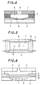
- Figs.1 and 2 are top and sectional views showing an ink-jet head of the first embodiment.
- a heating element 4 is arranged between a nozzle plate 1 and a substrate 2 with spacers 3, 3 disposed between the nozzle plate and heating element 4.
- a cavity 5 Formed between spacers 3 and 3 is a cavity 5 to be filled with ink while a nozzle 6 through which the ink is ejected is formed at the center of nozzle plate 1.
- a void 7 is formed as a thermally insulating layer under heating element 4. This void 7 is a space which is defined by a depressed portion formed in substrate 2 and between substrate 2 and heating element 4. This void 7 has the function of reducing the heat conduction between heating element 4 and substrate 2.
- the ink-jet head having the above configuration is constructed so that, upon ink ejection, a pulse of current is supplied from an unillustrated pulse generating power source so as to give off a pulse of heat from heating element 4. This heat vaporizes the ink within cavity 5 in an instant and forms bubbles therein to thereby eject ink from nozzle 6.
- heating element 4 of this ink-jet head will be described.
- heating element 4 is fixed with both ends fixed between spacer 3 and substrate 2 and is composed of a protective film 11, a heater 12 and an insulating film 13.
- This protective film 11 is to prevent adherence of ink in cavity 5 to heater 12.
- Insulation film 13 is to prevent electric leakage of the pulse current applied to heater 12 toward substrate 2.
- Heater 12 is configured of a metal thin-film having a high coefficient of thermal expansion and a high electric resistance.
- Heater 12 is adapted to give off heat by the application of a pulse current from the pulse generating power source so that the entire heating element 4 will be heated to a temperature (to be referred to hereinbelow as the bubbling temperature) which will permit the ink in cavity 5 to bubble by film boiling.
- interconnections 14 Arranged at both ends of heater 12 are interconnections 14 for supplying the pulse current from the pulse generating power source to heater 12.
- heating element 4 when the temperature of heating element 4 exceeds the bubbling temperature, heater 12 buckles due to heat energy (thermal expansion) so that the entire shape of heating element 4 deforms with its part put into contact with substrate 2.
- heating element 4 is kept horizontal (i.e., thermally insulated) with respect to substrate 2 at a temperature below the bubbling temperature. With its temperature exceeding the bubbling temperature, heater 12 will buckle, as shown in Fig. 4, and heating element 4 will be set flexed to the void 7 side until it comes into contact with substrate 2. That is, this flexure brings part of heating element 4 (heater 12) into contact with substrate 2 (into its heat radiating state). Thus, the heat from heating element 4 (heater 12) is dissipated to substrate 2 and discharged, so that heating element 4 will return to the thermally insulated state shown in Fig.3.
- Heater 12 is composed of nickel of 6.5 ⁇ m thick and 150 ⁇ m long, and heats to about 500°C providing the buckling start temperature of 370°C, to perform ink ejection.
- Nozzle plate 1 may be formed of a stainless steel etching plate, nickel-electroformed plate, photosensitive glass, precision molded plastic, etc.
- spacer 3 polyimide, nickel plating, dry film, etc. may be used.
- protective film 11 polyimide, SiO 2 , SiN, etc. may be used.
- interconnection 14 Ta, Ni, Au, Al, etc. may be used.
- heater 12 Ta, Ni, HfB 2 , etc. may be used.
- insulation film 13 polyimide, SiO 2 , SiN, etc. may be used.
- substrate 2 glass, ceramic, stainless steel, nickel, silicon, etc. can be used.
- the ink-jet head has void 7 between heating element 4 and substrate 2 so as to be able prevent heat conduction between heating element 4 and substrate 2. Therefore, it is possible to raise the temperature of heating element 4 in an instant to the bubbling temperature.
- heating element 4 buckles together with buckling of heater 12 so that part of the heating element comes into contact with substrate 2 to radiate heat. Therefore, heat from heating element 4 is discharged in a short time and hence the temperature of heating element 4 lowers quickly whereby the heating element returns to the thermally insulated state.
- the response frequency of heater 12 can be set approximately equal to the frequency of the applied pulse current. Therefore, it is possible to markedly precisely control the ejected amount of ink.
- heating element 4 is composed of protective film 11, heater 12 and insulation film 13, it is preferred that their materials should have approximately equal coefficients of thermal expansion. This is to prevent occurrence of cracks due to repeated heat cycles.
- a silicone oil should be applied over the contact area between heating element 4 and substrate 2. This will promote heat diffusion from heating element 4 to substrate 2.
- heating element 4 is fixed at both ends with spacer 3 and substrate 2.
- setting method of heating element 4 should not be limited to this. That is, heating element 4 may be set in any manner as long as heating element 4 is inhibited from moving in directions perpendicular to the thickness thereof (in the direction perpendicular to the document and the direction left and right direction in Fig.2).
- heater 12 is adapted to buckle and bring heating element 4 into contact with substrate 2 when the temperature of heating element 4 exceeds the buckling temperature.
- heater 12 should not occur necessarily with a large deformation. In other wards, heater 12 may and should warp in a degree to reduce the distance between heating element 4 and substrate 2 when the temperature of heating element 4 exceeds the buckling temperature. That is, the reduced distance between heating element 4 and substrate 2 will be able to cool heating element 4 (heater 12) from thermal diffusion to substrate 2.
- void 7 is formed by a depressed portion in substrate 2
- the configuration of void 7 should not be limited to this.
- communication holes 8 may be provided in substrate 2 so that void 7 and external air communicate with each other.
- This configuration can avoid the pressure rise in void 7 which would occur due to the deformation of heating element 4 so that heating element 4 will easily buckle. Further, since the air in void 7 can be ventilated through communication holes 8, cooling of heating element 4 (heater 12) can be promoted.
- void 7 communicates with cavity 5.
- void 7 will also be filled up with ink.
- heater 12 is composed of a metal membrane having a high coefficient of thermal expansion and a high electric resistance
- heater 12 may be formed of a laminated film made up of multiple number of metal membranes.
- a lamination of two different kinds of metals A and B, having different rates of thermal expansion may be used as heater 12 (insulation film 13 is omitted in Fig.7).
- heater 12 With a bimetallic configuration, it is possible to regulate the deforming direction of heater 12, in a controlled manner.
- heater 12 should buckle when the temperature of heater 12 exceeds the buckling temperature.
- this will not limit the configuration of heating element 4.
- a thin film of a shape memory alloy (SMP) 15 may be provided in the lowermost layer of heating element 4.
- shape memory alloy 15 when shape memory alloy 15 is set so that it takes a parallel state with respect to substrate 2 at lower temperature (see Fig.8A) and takes a deformed state when exceeding the deforming temperature (see Fig.8B), it is possible to realize deformation and cooling of heating element 4 in a beneficial manner. Thus, when such a shape memory alloy 15 is used, there is no need to select a material having a high rate of thermal expansion for heater 12.
- spontaneous shape deformation of heating element 4 is made use of in order to cool heater 12 when placing heating element 4 into contact with substrate 2. That is, the contact between heater 12 and substrate 2 can be attained by selecting a material for heater 12 or shape memory allow 15 so that it deforms into void 7 above the deforming temperature.
- the ink-jet head of the first embodiment should not be limited to this.
- the ink-jet head may employ a forcible thrusting method by using a piezoelectric actuator which forcibly pushes heating element 4 into void 7.
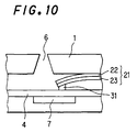
- Fig.9 is an illustrative view showing the fifth embodiment of an ink-jet head using this method. As shown in Fig.9, in this configuration, a piezoelectric actuator 21 is arranged on nozzle plate 1 so that it is directed to heating element 4.
- This piezoelectric actuator 21 is set so that it expand toward heating element 4 when a voltage from an unillustrated power source is applied thereto. Thus, heating element 4 is thrust into void 7 so as to come into contact with substrate 2.
- This configuration enables contact between heating element 4 and substrate 2 without depending upon the material of heater 12 or without using SMP 15. Since the amount of displacement of heating element 4 and its contact time with substrate 2 can be selected at will, it is possible to control the response frequency of heater 12 at a markedly high accuracy, thus making it possible to adjust the ejected amount of ink with precision.
- piezoelectric actuator 21 a laminated piezoelectric actuator having multiple number of layered piezoelectric elements is preferably used. In this case, it is preferred that the displacement of the piezoelectric elements in the direction of their thickness is used to thrust heating element 4.
- piezoelectric actuator 21 thin-film piezoelectric elements can be used.
- piezoelectric actuator 21 is provided in a laminated configuration (bimorph configuration) consisting of first and second piezoelectric films 22 and 23.
- This piezoelectric actuator 21 is set so that first piezoelectric film 22 expands along the film surface thereof while second piezoelectric film 23 contracts in the same direction when the voltage is applied.
- an abutment point 31 formed at the end of piezoelectric actuator 21 presses down heating element 4 so as to achieve contact between heating element 4 and substrate 2.
- first and second piezoelectric films 22 and 23 PZT (lead zirconium titanate) can be used.
- a metal thin-film such as of stainless steel may be used (uni-morph configuration). Also in this configuration, it is possible to realize beneficial deformation or displacement of piezoelectric actuator 21 while simplifying the configuration of piezoelectric actuator 21 and hence reducing the manufacturing cost.
- Figs. 11A and 11B are plan and sectional side views, respectively, showing a configuration of an ink-jet head in accordance with the seventh embodiment of the present invention.
- This ink-jet head 101 is configured so that a heater portion 104 is arranged between a first substrate 102 and a second substrate 103 with a nozzle plate 105 fixed to and along the one end face of substrates 102 and 103.
- a cavity 106 Formed between substrates 102 and 103 is a cavity 106 which will be filled with liquid ink.
- a nozzle 105a which allows cavity 106 to communicate with the exterior is formed in nozzle plate 105.
- Heater portion 104 is disposed in cavity 106.
- Heater portion 104 is composed of a heating element 104a, interconnections 104b, an insulation film 104c and a protective film 104d.
- Heating element 104a is formed of a thin plate made up of a metal such as Ni, etc., having a high coefficient of thermal expansion and a high electric resistance, and will heat by the electric supply of pulse current from an unillustrated drive circuit via interconnections 104b and bubbles the ink within cavity 106 by film boiling.
- Insulation film 104c provides electric insulation of heating element 104a and interconnections 104b from substrate 102.
- Protective film 104d provides watertightness of heating element 104a and interconnections 104b from and against the ink filling cavity 106.
- a spacing wall 107 is arranged between the top surface of heater portion 104 and substrate 103. This spacing wall 107 forms the space constituting cavity 106 between heater portion 104 and substrate 103.
- a void 108 is defined by the upper surface of substrate 102 which is disposed below, and opposing, heating element 104a of heater portion 104. This void 108 is formed so as to reduce the contact area of the undersurface of heater portion 104 with substrate 102.
- heater portion 104 One end in one direction within the surface, opposing substrates 102 and 103, of heater portion 104 abuts the inner surface of nozzle plate 105 while the other end is held between substrates 102 and 103 with spacing wall 107 interposed between substrate 103 and heater portion 104. Accordingly, movement of heater portion 104 is constrained at both ends with respect to the aforementioned one direction within the surface, opposing substrates 102 and 103, of heater portion 104.
- Figs. 12A and 12B are sectional side views schematically showing the deformation of a heater portion in the above ink-jet head. From heat generated from heating element 104a, heater 104 tries to expand in the directions indicated by the arrows in Fig.12A. However, since the displacement at both ends in the aforementioned one direction within the surface opposing substrates 102 and 103, a thermal stress occurs in the directions (contracting direction) shown by the arrows in Fig.12A. This thermal stress increases with the temperature rise of heating element 104a, and when the temperature of heating element 104a reaches the predetermined buckling temperature Tc, heater portion 104 will elastically deform (elastically buckle) due to thermal stress. Therefore, the buckling temperature Tc is a temperature at which elastic buckling of heater portion 104 starts.
- heating element 104a when the temperature of heating element 104a is below the buckling temperature Tc, heater portion 104 remains between substrates 102 and 103 and in parallel thereto, as shown in Fig.12A.
- Tc When the temperature of heating element 104a reaches the buckling temperature Tc, heater portion 104 buckles with its central part projected to the substrate 102 side.
- Tc When the temperature of heating element 104a has reached the heating temperature T which is higher than the buckling temperature Tc, heater portion 104 comes in contact with the upper surface of substrate 102 at its middle part as shown in Fig.12B. Therefore, this heating temperature T is the temperature when heater portion 104 comes into contact with substrate 102 and heating element 104a receives electric supply of pulse current until it reaches the heating temperature T.
- heating element 104a When the temperature of heating element 104a has reached the heating temperature T and its middle part comes into contact with the upper surface of substrate 102, heat arising in heating element 104a of heater portion 104 is discharged and conducted through substrate 102. If the supply of pulse current to heating element 104a is stopped at this moment, the temperature of heater portion 104 rapidly lowers. With this temperature drop, the thermal stress in heater portion 104 reduces whereby the heater portion 104 reverts back to its original state shown in Fig.12A by its own elasticity.
- heater portion 104 having reached at heating temperature T will be able to come into area contact with the upper surface of substrate 102, thus making it possible to efficiently discharge heat from heater portion 104.
- heating element 104a is formed of nickel of 6.5 ⁇ m thick, 10 ⁇ m wide and 150 ⁇ m long.
- Insulation film 104c is formed of SiO 2 of 0.1 ⁇ m thick.
- Protective film 104d is formed of polyimide of 0.1 ⁇ m thick.
- the depth of void 108 is set at 5 ⁇ m.
- L(q) 0 ⁇ 2 q 2 sin 2 ⁇ 1-q 2 sin 2 ⁇ d ⁇
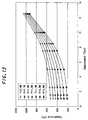
- Fig.13 shows the relationship between the temperature t of heater portion 104 and the amount of displacement Y for a heating element 104a of Ni with a coefficient of linear expansion ⁇ of 1.8 x 10 -5 and of 150 ⁇ m long(L) and 10 ⁇ m wide(D) when electric power consumption P is changed stepwise through 0.6 W, 0.9 W, 1.2 W, 1.5 W, 1.8 W, 2.1 W to 2.4 W and the thickness H is changed from 1.16 ⁇ m to 8.04 ⁇ m.
- heater portion 104 In order to provide an amount of displacement equal to or greater than 10 ⁇ m, heater portion 104 should be kept at an extremely high temperature, at 600 °C or higher. In order to save electric energy by reducing the power consumption P when heater portion 104 is moved within the void 8 into contact with substrate 102 by virtue of elastic deformation accompanying the temperature rise, the depth of void 8 should be 10 ⁇ m or smaller. When the depth of void 8 is set at 4 ⁇ m or smaller, the heating temperature T for causing heater portion 104 to come into contact with substrate 102 will not vary too much even if the depth of void 8 fluctuates when manufactured. Therefore, with this condition, it is possible to improve the production yield.
- Fig.14 shows the relationship between the ratio (L/H: thinness) of the length of heater portion 104 to the thickness and power consumption P for a heater portion 104 of Ni with a coefficient of linear expansion a of 1.8 x 10 -5 and of 150 ⁇ m long (L) and 10 ⁇ m wide (D) when the amount of displacement Y is changed stepwise as 1.0 ⁇ m, 1.5 ⁇ m, 2.5 ⁇ m, 5.0 ⁇ m, 7.5 ⁇ m, 8.5 ⁇ m, 10.0 ⁇ m and 12.5 ⁇ m while the heating temperature T is changed from 212°C to 1054°C at each displacement.
- Fig.15 shows relationships between the thinness L/H, and heating temperature T, and buckling temperature Tc when the displacement Y of heater portion 104 is at 2.5 ⁇ m.
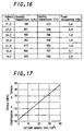
- Fig. 16 shows a relationship between the thinness L/H, heating temperature T, buckling temperature Tc, and power consumption P.
- heating temperature T and buckling temperature Tc become lower and hence the power consumption P becomes smaller.
- the depth of void 108 the amount of displacement Y of heater portion 104 set at 2.5 ⁇ m
- buckling temperature Tc is equal to 505°C
- heating temperature T is equal to 542°C
- power consumption P 2.4 W.
- buckling temperature Tc is equal to 212°C
- heating temperature T is equal to 835°C
- power consumption P 2.4 W.
- the ink when a type of ink having a bubbling temperature Tb of 212°C is used, the ink will be ejected when the temperature of the heater portion 104 reaches 212°C and then the heater portion 104 should be heated by 623°C higher to bring heater portion 104 into contact with substrate 102 to cool it down.
- the depth of void 108 should be determined so that the thinness L/H value will be equal to 15 or more, preferably 20 or more. This setting makes for reduction in the power consumption P and the temperature variation of heater portion 104, thus improving the durability.
- heater portion 104 has a lower buckling temperature Tc.
- a heater portion 104 is formed of a material having a coefficient of linear expansion ⁇ of 1x10 -5 /°C or greater, elastic buckling occurs at a lower temperature, making it possible to provide an ink-jet head configuration which has a small power consumption P and hence can provide an excellent durability.
- heater portion 104 When a type of ink having its bubbling temperature Tb equal to the heating temperature T of heater portion 104 is used, heater portion 104 will come into contact with substrate 102 almost at the same time as the ink is ejected. Accordingly, it is possible to provide an ink-jet head configuration which has the heating temperature T lowered and hence can provide an excellent durability.
- heater portion 104 When a type of ink having its bubbling temperature Tb equal to the buckling temperature Tc of heater portion 104 is used, heater portion 104 will start deformation when the ink is ejected. That is, at that moment, the heater portion 104 has not yet come into contact with substrate 102. So, heater portion 104 will radiate a lowered amount of heat so that it is possible to reduce the power consumption for heating heater portion 104.
- an internal stress in the direction parallel to the top surfaces of substrate 101 and 102 may be previously given to heater portion 104 so that it is possible to lower the buckling temperature Tc of heater portion 104.
- the formed heater portion 104 has an internal stress depending upon the current density as shown in Fig.17.
- the resultant heater 104 has a compressive stress of about 55 MPa acting in the surface direction. This compressive stress corresponds to the stress that would arise by a temperature rise of 14.6°C in the following formula (4).
- S E ⁇ T/(1 + ⁇ T)
- Figs.18A and 18B are sectional side views showing the essential components of ink-jet heads according to the eighth embodiment of the present invention.
- the heater portion is composed of two or three layers.
- heater portion 114 is configured of two layers, i.e., an upper layer 114a and a bottom layer 114b, which have been previously given tensile and compressive stresses, respectively.
- heater portion 124 is configured of three layers, i.e., an upper layer 124a, and a middle layer 124b and a bottom layer 124c, which have been previously given tensile stresses and compressive stresses, respectively.
- heater portion 114 or 124 has a multi-layered structure with each layer given a different internal stress as shown in Figs.18A and 18B
- the heater will buckle with its center projected to the side on which the layer, among the multiple layers in heater portion 114 or 124, receiving a stronger compressive stress is disposed.
- the layer which has a stronger compressive stress acting thereon compared to the other layers should expand greater and hence the heater portion 114 or 124 will curve with the layer having the greater expansion outside.
- heater portion 114 or 124 always buckles with its lower layer 114b or 124c, which has a greater compressive stress acting thereon compared to that on the upper layer 114a or 124a, projected so that heater portion 114 or 124 will positively come into contact with the upper surface of substrate 112 or 122 having void 128 or 128 formed therein.
- FIGs.19A and 19B are a plan view and a sectional side view cut along a plane 401-402, showing an ink-jet head according to the ninth embodiment of the present invention.
- An ink-jet head 201 has a substrate 206, a spacing wall member 205 and a top plate 204 arranged in layers from the bottom to the top in this order.
- a nozzle plate 203 Provided on one of the end faces defined by substrate 206, spacing wall member 205 and top plate 204, which has an opening communicating with an ink chamber (also referred to as cavity) formed in spacing wall member 205, is a nozzle plate 203. This nozzle plate is attached to the end face as it is oriented perpendicular to the direction of lamination of substrate 206, spacing wall member 205 and top plate 204.
- top plate 204 is a flat plate made up of a metal such as aluminum, iron, or the like.
- Nozzle plate 203 has an ejection nozzle 207 through which the ink inside ink chamber 202 is ejected. Ejection nozzle 207 provides communication between ink chamber 202 and ink-jet head 201.
- Heater portion 209 is composed of a heating element 209a, a protective film 209b and an insulation film 209c.
- Heating element 209a is a thin plate having an approximately circular shape made up of a metal such as nickel, nickel-chromium alloy, or the like, which has a high coefficient of thermal expansion and a high electric resistance.
- Heating element 209a is connected with electrodes 208a and 208b and heats when an unillustrated drive circuit supplies pulses of current thereto via electrodes 208a and 208b.
- an unillustrated drive circuit supplies pulses of current thereto via electrodes 208a and 208b.
- Heating element 209a elastically deforms at a temperature approximately equal to the bubbling temperature of the ink so that it slightly projects into ink chamber 202.
- the ink gives off bubbles.
- heater portion 209 including heating element 209a elastically deforms.
- Protective film 209b is to prevent adherence of ink in ink chamber 202 to heating element 209a and electrodes 208a and 208b.
- Protective film 209b is preferably formed of polyimide, silicon oxide, silicon nitride, or the like.
- Insulation film 209c provides electric insulation of heating element 209a and electrodes 208a and 208b from substrate 206.
- Insulation film 209c is preferably formed of silicon oxide, silicon nitride or the like.
- void 210 Formed in substrate 206 at the position under and opposing heater portion 209 is a void 210.
- This void 210 communicates with the exterior of ink-jet head 201 via a hole 211 formed in substrate 206 at a position opposing heater portion 209. Provision of void 210 reduces the contact area of the undersurface of heater portion 209 with substrate 206. Accordingly, heat transfer of the heat generated from heater element 209a of heater portion 209 toward substrate 206 is reduced, while the ink inside ink chamber 202 is quickly heated as the temperature of heater portion 209 increases rapidly.
- hole 11 equalizes the pressure inside void 210 to that outside ink-jet head 201. Therefore, when heater portion 209 elastically deforms, pressure inside void 210 will not lower, so as to permit heater portion 209 to elastically deform smoothly.
- Heater portion 209 is fixed at the entire periphery of void 210 formed in substrate 206. Therefore, when heater portion 209 is elastically deformed, the ink inside ink chamber 202 will not leak to void 210 or other parts.
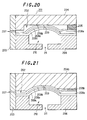
- Fig.20 is a sectional view showing the state where heater portion 209 has been elastically deformed.
- a pulse current is supplied to heating element 209a
- the ink inside ink chamber 202 heats in an instant.
- the temperature of heating element 209a reaches the bubbling temperature of the ink
- ink gives off bubbles therein.
- heating element 209a reaches its buckling temperature
- heater portion 209 flexes into ink chamber 202 in an instant by thermal stress, and comes into contact with top plate 204, as shown in Fig.20.
- top plate 204 As heater portion 209 abuts top plate 204, heat arising from heating element 209a of heater portion 209 is dissipated and directly conducted through top plate 204.
- top plate 204 is of metal and hence has a good heat radiation performance, so that it discharges heat quickly.
- heater portion 209 When the current supplied to heating element 209a is stopped, the temperature of heater portion 209 sharply lowers. With the reduction in temperature, the thermal stress acting on heater portion 209 decreases, so that heater portion 209 reverts back to its original state shown in Fig.19B by its own elasticity.
- heating element 209a has a substantially circular shape as stated already, so that with the same area, the heating element 209a of this embodiment is more liable to elastically deform than one having a rectangular shape, for example. Therefore, the configuration of this embodiment provides efficient ejection of ink droplets from ejection nozzle 207.
- heater portion 209 has a so-called diaphragm configuration which is fixed around the entire periphery of void 210, all the pressure arising in ink chamber 202 will act on the ink so as to eject ink droplets out.
- heating element 209a may be made compact compared to the conventional one and can reduce the power consumption required for heating element 209a to give off bubbles from the ink.
- heater portion 209 is cooled down quickly as the heat arising therefrom is released through top plate 204, this configuration provides a good response to the pulse current supplied to heating element 209a. Therefore, it is possible to control the ejected amount of ink at a high accuracy.
- Fig.21 is a sectional view showing another configuration of an ink-jet head according to the ninth embodiment of the present invention.
- a top plate 204b opposing heater portion 209 having heating element 209a is shaped in a form similar to the deformed shape of heating portion 209 and arranged so that heater portion 209 will come into area contact with top plate 204b when heating portion 209 has elastically deformed by thermal stress.
- heater portion 209 When a pulse current is supplied to heater portion 209 and the temperature reaches the temperature causing elastic deformation, heater portion 209 elastically deforms so that the face opposing top plate 204b comes into area contact with top plate 204b. As a result, heat from heater portion 209 transfers to top plate 204b of metal, and is quickly dissipated through top plate 204b. Accordingly, when the current supplied to heater portion 209 is stopped, the heater portion immediately reverts back to its original state shown in Fig.19B.
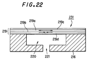
- Fig.22 is a sectional view showing another configuration of a heater portion 209 in an ink-jet head according to the ninth embodiment of the present invention. Since the configurations other than the heater portion are the same as in the ink-jet head 201 shown in Figs.19A and 19B, only the heater portion will be explained.
- heater portion 219 in order to regulate the direction of deformation of heater portion 219, the heating element is provided in a multi-layered configuration to adjust the stress therein.
- heater portion 219 has a two layered structure of a heating element 219a (upper layer) and a heating element 219b (lower layer), which have been previously given compressive stress and tensile stress, respectively.
- a protective film 219c is formed on the upper side of heating element 219a while an insulation film 219d is formed on the lower side of heating element 219b.
- Protective film 219c is to prevent adherence of ink in an unillustrated ink chamber to heating element 219a and unillustrated electrodes.
- Insulation film 219c provides electric insulation of heating element 219b and the unillustrated electrodes from a substrate 216.
- heater portion 219 has a multi-layered structure with each layer given a different internal stress
- heater portion 219 will buckle with its center projected to the side on which the layer, among the multiple layers in heater portion 219, receiving a stronger compressive stress is disposed.
- the layer which has a stronger compressive stress acting thereon compared to the other layers should expand greater and hence the heater portion 219 will curve with the layer having the greater expansion outside.
- heater portion 219 always elastically deforms with heating element 219a, which has a greater compressive stress acting thereon compared to that on the heating element 219b, projected so that heater portion 219 will positively come into contact with or come closer to top plate 204.
- heater portion 219 shown in Fig.22 for example, electrolytic plating in a nickel amidosulfonate bath for plating with the current density of 40 mA/cm 2 is effected over heating element 219b of 3 ⁇ m thick, to form a lower layer. Then, electrolytic plating with the current density of 1 mA/cm 2 is effected over heating element 219a of 3 ⁇ m thick, to form an upper layer.
- a tensile stress of about 55 MPa is given to the lower layer of heating element 219b, while a compressive stress of about 55 MPa is given to the upper layer of heating element 219a. Therefore, when heating to a temperature nearly equal to the bubbling temperature, heater portion 219 deforms toward top plate 204.
- heater portion 219 is formed in a multi-layered configuration with compressive and tensile stresses given to heating elements 219a and 219b, respectively. Also in ink-jet head 201 shown in Figs.19 and 20, when protective film 209b and insulation film 209c are given compressive and tensile stresses respectively while heating element 209a is adjusted to be free from stress, it is possible to cause heater portion 209 to elastically deform when the heater reaches a temperature nearly equal to the bubbling temperature.
- heater portion 219 is formed in a two-layered structure, it is also possible to have the same effects if the heater portion is formed in three or more layers, by adjusting the internal stress to be previously given to each layer.
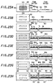
- Figs.23A to 23H are views showing a fabrication method of an ink-jet head of the seventh embodiment of the present invention.
- the plan view, the sectional view taken along a plane 303-304 in the plan view and the sectional view taken along a plane 301-302 in each step are shown from the left to the right.
- a void-forming material 108a of polyimide, Al or the like is formed with a thickness (e.g., 5 ⁇ m) corresponding to the depth of void 108 to be formed, over the top surface of first substrate 102 of glass or metal by a spinner, sputtering or other means.
- a photoresist corresponding to the plan shape of void 108 is patterned over the top surface.
- Void-forming material 108a is etched by a 1N NaOH solution or the like leaving the flat shape of void 108.
- the photoresist remaining on the top of the plan shape of void 108 is removed.
- a solid shape of void 108 is formed on the top surface of substrate 102 by void-forming material 108a (Fig.23A).
- SiO 2 or the like is film formed by sputtering or other means so as to provide an insulation film 104c having a predetermined thickness (e.g., 0.1 ⁇ m) over the top of substrate 102 having the solid shape of void-forming material 108a for void 108. Then, dry etching such as RIE (reactive ion etching) with CF 4 gas is performed using a photoresist. Then the photoresist is removed. By this process, insulation film 104c is formed over the top surface of substrate 102 except part of the top surface of void-forming material 108a (Fig.23B).
- RIE reactive ion etching
- Ta of 100 ⁇ thick and Ni of 200 ⁇ thick are film formed by sputtering or other means in this order on the top surface of substrtae 102 including void-forming material 108a and insulation film 104c. Then, etching is performed using a photoresist and then the photoresist is removed. By this process, Ta film for improving the adhesion between insulation film 104a and Ni forming heating element 104a and an Ni film for the surface backing of Ni plating forming heating element 104a are formed over top surface of substrte 102 except part of the top surface of void-forming material 108a (Fig.23C).
- insulation film 104c, Ta film and Ni film are formed on the top of the void-forming material in such a manner that the area of each layer in the plan view becomes marginally smaller than the area of the lower layer, whereby heating element 104a to be formed on the top of the Ni film will be positively coated by insulation film 104c.
- a negative type photoresist is applied with the same thickness (e.g., 6.5 ⁇ m) as the film thickness of heating element 104a over the top surface of substrate 102 having the void-forming material, insulation film 104c, the Ta film, the Ni film formed thereon, and then the shape correspoidng to the solid shape of heating element 104a to be formed is patterned.
- a negative type photoresist is by reason of its suitablity of forming tapering shapes for heating element 104a.
- the Ni film is formed by electroytically plating in a nickel amidosulfonate bath having a pH of 4.4 with the current density set at 20 mA/cm 2 at a temperature of 50°C so as to form an Ni layer having the thikness of heating element 104a in the area other than a photoresist 131 patterned over the top surface of substrate 102 (Fig.23D).
- a nickel amidosulfonate bath having a pH of 4.4 with the current density set at 20 mA/cm 2 at a temperature of 50°C so as to form an Ni layer having the thikness of heating element 104a in the area other than a photoresist 131 patterned over the top surface of substrate 102 (Fig.23D).
- Fig.17 no internal stress will occur in the Ni layer formed by the electroytically plating under the above-mentioned conditions.
- a photoresist pattern for interconnections are formed on the top surface of the Ni layer. Then, electroytic plating in a nickel amidosulfonate bath is peformed under predetermined conditions with the Ni layer used as the electrode, so as to form interconnections 104b for heating element 104a with a predetermined thickness (e.g., 10 ⁇ m) over the top surface of the Ni layer (Fig.23E).
- a predetermined thickness e.g. 10 ⁇ m
- the substrate 102 having heating element 104a and interconnections 104b formed thereon by the above process is immersed in a 1N NaOH solution so as to remove photoresist 131 and void-forming material 108a.
- void 108 having the depth corresponding to the film thickness of void-forming material 108a is formed in the portion opposing the bottom face of heating element 104a on the top surface of substrate 102 (Fig.23F).
- a film of SiO 2 , SiN or the like having a predetermined thickness is formed as protective film 104d by sputtering, vapor deposition or other methods, over the top surface of the Ni layer with photoresist 131 and void-forming material 108a removed, except on the top surface of interconnections 104b. Then the photoresist over interconnections 104b is removed by the lift-off method using acetone etc., or other methods. This completes the formation of heater portion 104 on substrate 102 (Fig.23G).
- polyimide, dry film etc. are formed with a predetermined shape having a predetermined thickness (e.g., 10 ⁇ m) over the top of part of interconnections 104b and part of protective film 104d to form spacing wall 107.
- second substrate 103 of glass etc. is bonded to the top surface of spacing wall 107.
- nozzle plate 105 having a nozzle 105a formed therein is bonded to the end face of substrates 102 and 103.
- Figs.24A and 24B are views showing another fabrication method of an ink-jet head of the seventh embodiment of the present invention.
- the plan view, the sectional view taken along a plane 303-304 in the plan view and the sectional view taken along a plane 301-302 in each step are shown from the left to the right.
- insulation film 104c is formed (Fig. 24A) on a first substrate 102 made up of Si, of which the top surface is entirely covered with a thermal oxidation film 102a, in the same manner as shown in Fig.23B.
- thermal oxidation film 102a on the surface of substrate 102 in the lower part of heater portion 104 is removed by etching with hydrofluoric acid (HF) so as to form void 108 between substrate 102 and heater portion 104 (Fig.24B).
- insulation film 104c and protective film 104d needs to be composed of SiN so as not to be etched by HF.
- void 108 can be formed without providing void-forming material 108a, thus making it possible to simplfy the production process of ink-jet head 101 and hence reduce the cost. Since the film thickness of thermal oxidation film 102a formed on the top surface of substrate 102 can be controlled to be 1 ⁇ m or below, it is possible to set the depth of void 108 to be relatively shallow, thus making it possible to impove the heat radiation efficiency. Further, since it is easy to uniformly form thermal oxidation film 102a over the top surface of substrate 102, improved production yiled can be obtained.
- Figs.25A, 25B and 25C are views showing a fabrication method of an ink-jet head of the eighth embodiment of the present invention.
- the electrolytic plating process for the Ni layer constituting heating element 104a shown in Fig.23D is effected by multiple steps using different current densities from one another, which are controlled based on the relationship shown in Fig.17.
- heater portion 114 is formed with the first layer 141 located on the lower part given with a compressive stress of about 55 MPa and the second layer 142 located on the upper part given with no internal stress.
- heater portion 114 is formed with the second layer 142 located on the upper part given with a compressive stress of about 55 MPa and the first layer 141 located on the lower part given with no internal stress.
- the heater portion 114 may be adapted to deform toward the upper substrate. That is, by controlling the current density during the electrolytic plating process for preparation of heating portion 114, it is possible to make heater portion 114 deform toward either substrate 112 or the upper substrate, taking into account the efficiency of heat radiation.
- heater portion 114 is formed with the first layer 141 located on the lower part given with a compressive stress of about 55 MPa and the second layer 142 located on the upper part given with a tensile stress of about 55 MPa.
- the compressive stress acting on first layer 141 in the heated, heater portion 114 becomes markedly greater than the compressive stress acting on second layer 142, the middle part of heater portion 114 will positively come into contact with the top surface of substrate 112.
- the present invention provides the effects as follows:-
- a void is arranged between the heating element and the head substrate so that the heating element will buckle into the void by thermal expansion accompanying the temperature rise thereof. Therefore, heat diffusion from the heating element is prevented by the insulating effect of the void when ink is heated, enabling its sharp temperature rise. After ink ejection, the heating element buckles so that heat from the heating element is released through the head substrate to lower the temperature of the heating element rapidly, thus providing reliable ink ejection control.
- the heating element is composed of a heater, a protective film for protecting the heater, and an insulation film for insulating the heater and the above components are formed of materials having approximately equal coefficients of linear expansion to each other. Therefore, it is possible to prevent occurrence of cracks due to repeated heat cycles.
- the heating element is arranged with its movement constrained at both ends with respect to the direction of the thickness and the direction perpendicular to the thickness, it is possible to positively cause the heating element to buckle toward the void.
- the heating element is configured so as to come into contact with the head substrate when buckled into the void, heat from the heating element can be well dissipated through thermal conduction via its contact with the head substrate, whereby it is possible to achieve high accuracy control of the ejected amount of ink.
- the ink since the void is arranged so as to communicate with a cavity that stores ink, the ink functions as the heat transfer medium when the heating element release heat thus improving the heat transfer to the head substrate and hence enabling beneficial heat radiation.
- the head substrate since the head substrate has a communication hole for establishing communication between the void and the exterior, heat inside the void can be released outside through the communication hole, thus improving the heat radiation efficiency of the heating element.
- a void is arranged between the heating element and the head substrate, and the heating element is provided in a bimetal configuration made up of multiple kinds of metals so as to cause the heating element to deform into the void by the temperature rise thereof. Therefore, the direction of deformation of the heating element can be determined simply with the achievement of reliable deformation into the void, thus providing high accuracy control of the ejected amount of ink.
- a void is arranged between the heating element and the head substrate, and the heating element is formed with a shape memory alloy layer which will deform into the void when the heating element exceeds a predetermined temperature. Therefore, the direction of deformation of the heating element can be determined simply with the achievement of reliable deformation into the void, thus providing high accuracy control of the ejected amount of ink.
- a void is arranged between the heating element and the head substrate, and the ink-jet head further includes a piezoelectric actuator which pushes and deforms the heating element toward the void. Therefore, the direction of deformation of the heating element can be determined simply with the achievement of reliable deformation into the void, thus providing high accuracy control of the ejected amount of ink.
- the heating element arranged out of contact with the first and second substrates can be elastically deformed by thermal stress during heating into contact with the first or second substrate.
- the heat generated in the heating element will not dissipate through the substrate while the heating element heats, thus making it possible to efficiently heat the ink in contact with the heating element.
- heat remaining in the heating element after the completion of heating of the heating element will be dissipated through the first or second substrate in contact, thus making it possible to cool down the heating element quickly, which results in improvement of the ink ejection response to the print data.
- the heating element since the heating element is quickly deformed by elastic buckling when the heating element reaches the predetermined temperature, the heating element can be set quickly closer to or brought into contact with the first or second substrate in response to the temperature change, thus making it possible to cool down the heating element rapidly.
- the heating element which has elastically deformed by its own heat comes into area contact with the first or second substrate, a large amount of heat can be released from the heating element through the first or second substrate in contact, thus making it possible to cool down the heating element quickly, which leads to improvement of the ink ejection response to the print data.
- the heating element is fixed at both ends with respect to at least one direction within its surface opposing the first or second substrate so that the heating element will not be moved at both ends by thermal deformation during heating.
- the mid part of the heating element can be moved closer to or into contact with the first or second substrate by the elastic deformation arising during heating, thus making it possible to positively release heat remaining in the heating element by way of the substrate.
- the heating element is fixed at the entire periphery of its surface opposing the first or second substrate and held between the first and second substrates so that the heating element will not be moved at the periphery thereof by thermal deformation during heating.
- the central part of the heating element can be moved closer to or into contact with the first or second substrate by the elastic deformation arising during heating, thus making it possible to positively release heat remaining in the heating element by way of the substrate.
- the heating element is brought closer to or brought into contact with the first or second substrate by elastic deformation when the ink has been heated approximately close to the bubbling temperature. Therefore, it is possible to cool down the heating element by the heat radiation of the first or second substrate immediately after the ejection of bubbling ink from the nozzle. Therefore, it is possible to prevent the temperature of the heating element from lowering before completion of the ink ejection, which leads to improvement of the ink ejection response to the print data.
- the heating element before heating has been previously given a residual stress causing compression with respect to one direction within the surface thereof opposing the first or second substrate.
- the heating element can be elastically deformed in a reliable manner by the thermal stress arising in the compressing direction during heating.
- this configuration also contributes to lowering the temperature of the heating element to cause the heating element itself to be elastically deformed into the predetermined shape, thus making it possible to reduce the power consumption.
- the heating element is provided in the form of a plate having a multi-layered configuration in which an internal stress has been given previously in its unheated state so as to determine the direction of elastic deformation when the heating element heats. Therefore, the heating element will positively deform in the predetermined direction when it is heated.
- the heating element for heating the ink and giving off bubbles in order to eject the ink from the ejection will elastically deform toward the interior of the ink chamber when it is activated and reaches the predetermined temperature. Therefore, the pressure arising when bubbles expand and the pressure arising when the heating element elastically deforms act on the ink and hence the ink droplets can be ejected outside the ink-jet head by the combined pressure.
- This configuration contributes to reduce the current to be supplied to the heating element to bubble the ink, thus making it possible to reduce the power consumption.
- the void which is formed below the heating element provided in the ink chamber functions as the insulation layer when the heating element heat by supplying a pulse of current. Therefore, heat diffusion from the heating element to the substrate can be inhibited, thus enabling sharp temperature rise of the heating element, which leads to improved efficiency of ink ejection.
- the void provided below the heating element is made in communication with the exterior of the ink-jet head, it is possible to prevent reduction in the pressure in the void, which enables smooth elastic deformation of the heating element.
- the heating element when the heating element is heated and reaches the predetermined temperature by supplying electric current, the heating element elastically deforms by thermal stress and comes into contact with the surface of the ink chamber opposing the heating element. Therefore, heat arising in the heating element is released through the abutment of the heating element with the surface of the in chamber opposing the heating element, thus making it possible to cool the heating element quickly after the generation of bubbles. As a result, an improved heating and cooling response to the selectively activated pulse current can be achieved, thus making it possible to control the ejected amount of ink with high precision.
- the heating element having been elastically deformed by heating is brought into area contact with the opposing surface which opposes the heating element. Therefore, the heating element can be brought into contact with the surface opposing the heating element through an enlarged area, thus improving the heat radiation efficiency and enabling rapid cooling of the heating element.
- the heating element since in the heating element having a multi-layered configuration, the outermost layer facing the interior of the ink chamber has been previously given an internal stress causing compression, the heating element can be always deformed elastically in the fixed direction when the heating element is heated by supplying current and reaches the elastically deforming temperature.
- the heating element provided in the ink chamber is fixed at the entire periphery thereof to the bottom face of the ink chamber, it is possible to positively deform the heating chamber towards the interior of the ink chamber when it elastically deforms from heating. It is also possible to eject ink without any leakage of ink from the periphery of the heating element when the elastic element elastically deforms.
- the heating element arranged in the ink chamber is formed in an approximately circular shape, this configuration provides large displacement of the heating element when it is elastically deformed, compared to other shapes having the same area. Therefore, it is possible to apply a greater pressure on the ink in the ink chamber.
- a void can be formed between the heating element and the first substrate by removing the void-forming material from the top surface of the first substrate after the formation of the heating element, it is possible to easily fabricate an ink-jet head having a void between the first substrate, and the second substrate and the heating element.
- the heating element is formed as a plated layer by electrolytic plating so as to previously give an internal stress causing compression to the heating element, it is possible to easily fabricate an ink-jet head having a heating element which can be elastically deformed in a reliable manner.
- the heating element is formed by electrolytic plating using different current densities which affect the internal stresses to be given to the plated layers, it is possible to easily fabricate an ink-jet head having a heating element which can elastically deform in the predetermined direction in a reliable manner when it is heated.
Landscapes
- Engineering & Computer Science (AREA)
- Manufacturing & Machinery (AREA)
- Particle Formation And Scattering Control In Inkjet Printers (AREA)
Abstract
Description
- S:
- the stress in the plated layer (N/m2)
- E:
- Young's modulus (2.1 x 10¹¹ N/m2 for Ni)
- α:
- coefficient of linear expansion ((1.8 x 10⁻⁵ /°C for Ni)
- T:
- temperature (°C).
Claims (30)
- An ink-jet head for ejecting ink by heating and bubbling ink, comprising:a heating element to which electric current is supplied so as to heat and bubble the ink; anda head substrate having a void formed between the heating element and the head substrate,
characterized in that the heating element will buckle into the void by thermal expansion accompanying the temperature rise thereof. - The ink-jet head according to Claim 1, wherein the heating element comprises: a heater; a protective film for protecting the heater; and an insulation film for insulating the heater and the above components are formed of materials having approximately equal coefficients of linear expansion to each other.
- The ink-jet head according to Claim 1, wherein the heating element is arranged with its movement constrained at both ends with respect to the direction of the thickness and the direction perpendicular to the thickness.
- The ink-jet head according to Claim 1, wherein the heating element is configured so as to come into contact with the head substrate when buckled into the void.
- The ink-jet head according to Claim 1, wherein the void is arranged so as to communicate with a cavity that stores ink.
- The ink-jet head according to Claim 1, wherein the head substrate has a communication hole for establishing communication between the void and the exterior.
- An ink-jet head for ejecting ink by heating and bubbling ink, comprising:a heating element to which electric current is supplied so as to heat and bubble the ink; anda head substrate having a void formed between the heating element and the head substrate,
characterized in that the heating element is provided in a bimetal configuration made up of multiple kinds of metals so as to cause the heating element to deform into the void by the temperature rise thereof. - An ink-jet head for ejecting ink by heating and bubbling ink, comprising:a heating element to which electric current is supplied so as to heat and bubble the ink; anda head substrate having a void formed between the heating element and the head substrate,
characterized in that the heating element is formed with a shape memory alloy layer which will deform into the void when the heating element exceeds a predetermined temperature. - An ink-jet head for ejecting ink by heating and bubbling ink, comprising:a heating element to which electric current is supplied so as to heat and bubble the ink;a head substrate having a void formed between the heating element and the head substrate; anda piezoelectric actuator which pushes and deforms the heating element toward the void.
- An ink-jet head for ejecting ink from a nozzle by heating and bubbling ink, comprising:a first substrate;a second substrate arranged opposing the first substrate, defining a space to be filled with ink in corporation with the first substrate; anda heating element disposed between the first and second substrates and having a voltage selectively applied thereto so that the ink inside the space is heated and bubbled, characterized in that the heating element is arranged between the first and second substrates with clearances from both, and the heating element comes closer to or in contact with the first or second substrate by elastic deformation occurring from thermal stress during heating.
- The ink-jet head according to Claim 10, wherein the elastic deformation is elastic buckling that occurs when the temperature of the heating element reaches the predetermined temperature.
- The ink-jet head according to Claim 10, wherein the first or second substrate has an opposing surface which allows area contact with the heating element when it is elastically deformed.
- The ink-jet head according to Claim 10, wherein the heating element is provided in the form of a plate that is fixed at both ends with respect to at least one direction within the surface thereof opposing the first or second substrate.
- The ink-jet head according to Claim 13, wherein the heating element is provided in the form of a plate that is fixed at the entire periphery of the surface thereof opposing the first or second substrate and held between the first and second substrates.
- The ink-jet head according to Claim 10, wherein the heating element elastically deforms by thermal stress arising at a temperature approximately equal to the bubbling temperature of the ink.
- The ink-jet head according to Claim 10, wherein the heating element has been previously given an internal stress causing compression with respect to one direction within the surface thereof opposing the first or second substrate.
- The ink-jet head according to Claim 10, wherein the heating element is provided in the form of a plate having a multi-layered configuration in which an internal stress has been previously given so as to determine the direction of elastic deformation when the heating element heats.
- An ink-jet head for ejecting ink comprising:an ejection nozzle for ejecting ink;an ink chamber arranged in communication with the ejection nozzle; anda heating element disposed in the ink chamber, which gives off bubbles by heating the ink in contact with the heating element by selective activation and causes ink ejection from the ejection nozzle making use of the pressure arising when the bubbles expand,
characterized in that the heating element elastically deforms toward the ink chamber when it reaches the predetermined temperature. - The ink-jet head according to Claim 18, wherein a void is formed below the heating element.
- The ink-jet head according to Claim 19, wherein the void is made in communication with the exterior.
- The ink-jet head according to Claim 18, wherein the heating element abuts the surface of the ink chamber opposing the heating element when the heating element reaches the predetermined temperature.
- The ink-jet head according to Claim 21, wherein the ink chamber has an opposing surface which opposes the heating element so as to allow area contact with the heating element when the heating element is elastically deformed.
- The ink-jet head according to Claim 18, wherein the heating element has a multi-layered configuration in which the outermost layer facing the interior of the ink chamber has been previously given an internal stress causing compression.
- The ink-jet head according to Claim 18, wherein the heating element is fixed at the entire periphery thereof to the bottom face of the ink chamber.
- The ink-jet head according to Claim 18, wherein the heating element is of an approximately circular shape.
- A fabrication method of an ink-jet head, comprising the steps of:forming an void-forming material and a heating element on the top of a first substrate, in this sequential order;removing the void-forming material; andarranging a second substrate a predetermined distance away from the top surface of the heating element.
- The fabrication method of an ink-jet head according to Claim 26, wherein the formation of the heating element includes an electrolytic plating step with such a current density that the plated layer will have an internal stress causing compression.
- The fabrication method of an ink-jet head according to Claim 26, wherein the formation of the heating element includes electrolytic plating steps using different current densities.
- An ink jet head having a heating element, a portion of which is disposed for heating the ink in an ink chamber when energized so that it bubbles and causes ink to eject from the head, said portion being spaced, at the start of energization, from the ink chamber walls and from a support member which supports said heating element relative to the chamber, the arrangement being such that after said start of energization said portion of the heating element moves toward said support member or chamber wall so as to hasten the cooling of the heating element.
- An ink jet head in which a heating element moves toward or into cooling contact with an internal surface of a head substrate or ink chamber following initial energization for ink ejection.
Applications Claiming Priority (6)
| Application Number | Priority Date | Filing Date | Title |
|---|---|---|---|
| JP18103899A JP3495649B2 (en) | 1999-06-28 | 1999-06-28 | Inkjet head |
| JP18103899 | 1999-06-28 | ||
| JP27670599 | 1999-09-29 | ||
| JP27670599A JP2001096749A (en) | 1999-09-29 | 1999-09-29 | Ink jet head and method of manufacturing the same |
| JP30042499A JP2001113704A (en) | 1999-10-22 | 1999-10-22 | Inkjet head |
| JP30042499 | 1999-10-22 |
Publications (3)
| Publication Number | Publication Date |
|---|---|
| EP1066966A2 true EP1066966A2 (en) | 2001-01-10 |
| EP1066966A3 EP1066966A3 (en) | 2001-07-04 |
| EP1066966B1 EP1066966B1 (en) | 2005-12-21 |
Family
ID=27324948
Family Applications (1)
| Application Number | Title | Priority Date | Filing Date |
|---|---|---|---|
| EP00305062A Expired - Lifetime EP1066966B1 (en) | 1999-06-28 | 2000-06-15 | Ink-jet head and fabrication method of the same |
Country Status (3)
| Country | Link |
|---|---|
| US (1) | US6340223B1 (en) |
| EP (1) | EP1066966B1 (en) |
| DE (1) | DE60024926T2 (en) |
Cited By (1)
| Publication number | Priority date | Publication date | Assignee | Title |
|---|---|---|---|---|
| WO2010011250A3 (en) * | 2008-06-23 | 2010-04-15 | Eastman Kodak Company | Printhead having isolated heater |
Families Citing this family (7)
| Publication number | Priority date | Publication date | Assignee | Title |
|---|---|---|---|---|
| KR20020025588A (en) * | 2000-09-29 | 2002-04-04 | 윤종용 | Ink-jet printer head |
| JP4719978B2 (en) * | 2001-01-11 | 2011-07-06 | ソニー株式会社 | Printer, printer head and printer head manufacturing method |
| US6755509B2 (en) * | 2002-11-23 | 2004-06-29 | Silverbrook Research Pty Ltd | Thermal ink jet printhead with suspended beam heater |
| US7470010B2 (en) * | 2005-10-11 | 2008-12-30 | Silverbrook Research Pty Ltd | Inkjet printhead with multiple ink inlet flow paths |
| US8414786B2 (en) * | 2008-11-05 | 2013-04-09 | Lexmark International, Inc. | Planar heater stack and method for making planar heater stack with cavity within planar heater substrata above substrate |
| US8172370B2 (en) * | 2008-12-30 | 2012-05-08 | Lexmark International, Inc. | Planar heater stack and method for making planar heater stack |
| KR20150046644A (en) * | 2013-10-22 | 2015-04-30 | 삼성전자주식회사 | Resin dispenser for nano-imprint |
Citations (2)
| Publication number | Priority date | Publication date | Assignee | Title |
|---|---|---|---|---|
| JPH023054A (en) | 1988-06-20 | 1990-01-08 | Nippon Telegr & Teleph Corp <Ntt> | Pattern forming material |
| JPH07227968A (en) | 1994-02-21 | 1995-08-29 | Canon Inc | Ink jet recording head and manufacturing method thereof |
Family Cites Families (7)
| Publication number | Priority date | Publication date | Assignee | Title |
|---|---|---|---|---|
| US5666141A (en) | 1993-07-13 | 1997-09-09 | Sharp Kabushiki Kaisha | Ink jet head and a method of manufacturing thereof |
| JPH0890769A (en) | 1994-09-27 | 1996-04-09 | Sharp Corp | Diaphragm type inkjet head with folds |
| JPH08309980A (en) | 1995-05-17 | 1996-11-26 | Sharp Corp | INKJET HEAD AND METHOD OF MANUFACTURING THE SAME |
| JPH0985946A (en) * | 1995-09-25 | 1997-03-31 | Sharp Corp | Ink jet head and method of manufacturing the same |
| US5812163A (en) | 1996-02-13 | 1998-09-22 | Hewlett-Packard Company | Ink jet printer firing assembly with flexible film expeller |
| KR100221459B1 (en) | 1997-03-07 | 1999-09-15 | 이형도 | Recording liquid ejecting apparatus and method thereof of print head |
| US6130689A (en) * | 1997-11-19 | 2000-10-10 | Samsung Electro-Mechanics Co., Ltd. | Apparatus and actuator for injecting a recording solution of a print head and method for producing the apparatus |
-
2000
- 2000-06-02 US US09/585,406 patent/US6340223B1/en not_active Expired - Lifetime
- 2000-06-15 DE DE60024926T patent/DE60024926T2/en not_active Expired - Lifetime
- 2000-06-15 EP EP00305062A patent/EP1066966B1/en not_active Expired - Lifetime
Patent Citations (2)
| Publication number | Priority date | Publication date | Assignee | Title |
|---|---|---|---|---|
| JPH023054A (en) | 1988-06-20 | 1990-01-08 | Nippon Telegr & Teleph Corp <Ntt> | Pattern forming material |
| JPH07227968A (en) | 1994-02-21 | 1995-08-29 | Canon Inc | Ink jet recording head and manufacturing method thereof |
Cited By (2)
| Publication number | Priority date | Publication date | Assignee | Title |
|---|---|---|---|---|
| WO2010011250A3 (en) * | 2008-06-23 | 2010-04-15 | Eastman Kodak Company | Printhead having isolated heater |
| US8540349B2 (en) | 2008-06-23 | 2013-09-24 | Eastman Kodak Company | Printhead having isolated heater |
Also Published As
| Publication number | Publication date |
|---|---|
| DE60024926T2 (en) | 2006-08-17 |
| EP1066966B1 (en) | 2005-12-21 |
| DE60024926D1 (en) | 2006-01-26 |
| US6340223B1 (en) | 2002-01-22 |
| EP1066966A3 (en) | 2001-07-04 |
Similar Documents
| Publication | Publication Date | Title |
|---|---|---|
| EP0634273B1 (en) | Ink jet head and a method of manufacturing thereof | |
| US5912684A (en) | Inkjet recording apparatus | |
| JP3851812B2 (en) | Ink jet print head and manufacturing method thereof | |
| US7566113B2 (en) | Inkjet nozzle incorporating serpentine actuator | |
| JP3351427B2 (en) | Inkjet head | |
| JPH07285221A (en) | Inkjet head | |
| US7758165B2 (en) | Ink-jet printhead and manufacturing method thereof | |
| JP3773843B2 (en) | Method of manufacturing an ink jet print head having a hemispherical ink chamber | |
| JP3851814B2 (en) | Ink jet print head having hemispherical ink chamber and method of manufacturing the same | |
| JP3495649B2 (en) | Inkjet head | |
| US6340223B1 (en) | Ink-jet head and fabrication method of the same | |
| US5757401A (en) | Ink jet head, method of using thereof and method of manufacturing thereof | |
| KR100641357B1 (en) | Inkjet Printheads and Manufacturing Method Thereof | |
| JPH091795A (en) | Inkjet head | |
| US6142616A (en) | Ink jet recording head | |
| JP2004209740A (en) | Liquid ejection head | |
| JP2003118114A (en) | Ink jet head and method of manufacturing the same | |
| JP4003917B2 (en) | Droplet discharge head and manufacturing method thereof | |
| US8366243B2 (en) | Printhead integrated circuit with actuators proximate exterior surface | |
| JP2927765B2 (en) | Printer head recording liquid ejecting apparatus and method | |
| JP2001179988A (en) | Nozzle forming member, inkjet head, and inkjet recording apparatus | |
| JP2001096749A (en) | Ink jet head and method of manufacturing the same | |
| JP2001113704A (en) | Inkjet head | |
| KR100337112B1 (en) | Printer head | |
| JPH0820108A (en) | Inkjet head and manufacturing method thereof |
Legal Events
| Date | Code | Title | Description |
|---|---|---|---|
| PUAI | Public reference made under article 153(3) epc to a published international application that has entered the european phase |
Free format text: ORIGINAL CODE: 0009012 |
|
| AK | Designated contracting states |
Kind code of ref document: A2 Designated state(s): DE FR GB |
|
| AX | Request for extension of the european patent |
Free format text: AL;LT;LV;MK;RO;SI |
|
| PUAL | Search report despatched |
Free format text: ORIGINAL CODE: 0009013 |
|
| AK | Designated contracting states |
Kind code of ref document: A3 Designated state(s): AT BE CH CY DE DK ES FI FR GB GR IE IT LI LU MC NL PT SE |
|
| AX | Request for extension of the european patent |
Free format text: AL;LT;LV;MK;RO;SI |
|
| 17P | Request for examination filed |
Effective date: 20010919 |
|
| AKX | Designation fees paid |
Free format text: DE FR GB |
|
| 17Q | First examination report despatched |
Effective date: 20041125 |
|
| GRAP | Despatch of communication of intention to grant a patent |
Free format text: ORIGINAL CODE: EPIDOSNIGR1 |
|
| GRAP | Despatch of communication of intention to grant a patent |
Free format text: ORIGINAL CODE: EPIDOSNIGR1 |
|
| GRAS | Grant fee paid |
Free format text: ORIGINAL CODE: EPIDOSNIGR3 |
|
| GRAA | (expected) grant |
Free format text: ORIGINAL CODE: 0009210 |
|
| AK | Designated contracting states |
Kind code of ref document: B1 Designated state(s): DE FR GB |
|
| REG | Reference to a national code |
Ref country code: GB Ref legal event code: FG4D |
|
| REF | Corresponds to: |
Ref document number: 60024926 Country of ref document: DE Date of ref document: 20060126 Kind code of ref document: P |
|
| ET | Fr: translation filed | ||
| PLBE | No opposition filed within time limit |
Free format text: ORIGINAL CODE: 0009261 |
|
| STAA | Information on the status of an ep patent application or granted ep patent |
Free format text: STATUS: NO OPPOSITION FILED WITHIN TIME LIMIT |
|
| 26N | No opposition filed |
Effective date: 20060922 |
|
| PGFP | Annual fee paid to national office [announced via postgrant information from national office to epo] |
Ref country code: FR Payment date: 20100709 Year of fee payment: 11 |
|
| PGFP | Annual fee paid to national office [announced via postgrant information from national office to epo] |
Ref country code: GB Payment date: 20100609 Year of fee payment: 11 Ref country code: DE Payment date: 20100610 Year of fee payment: 11 |
|
| GBPC | Gb: european patent ceased through non-payment of renewal fee |
Effective date: 20110615 |
|
| REG | Reference to a national code |
Ref country code: FR Ref legal event code: ST Effective date: 20120229 |
|
| REG | Reference to a national code |
Ref country code: DE Ref legal event code: R119 Ref document number: 60024926 Country of ref document: DE Effective date: 20120103 |
|
| PG25 | Lapsed in a contracting state [announced via postgrant information from national office to epo] |
Ref country code: DE Free format text: LAPSE BECAUSE OF NON-PAYMENT OF DUE FEES Effective date: 20120103 Ref country code: FR Free format text: LAPSE BECAUSE OF NON-PAYMENT OF DUE FEES Effective date: 20110630 |
|
| PG25 | Lapsed in a contracting state [announced via postgrant information from national office to epo] |
Ref country code: GB Free format text: LAPSE BECAUSE OF NON-PAYMENT OF DUE FEES Effective date: 20110615 |