EP1066910A1 - Poste de soudage à l'arc avec alternance de périodes d'arc et de périodes de court circuit. - Google Patents
Poste de soudage à l'arc avec alternance de périodes d'arc et de périodes de court circuit. Download PDFInfo
- Publication number
- EP1066910A1 EP1066910A1 EP00401802A EP00401802A EP1066910A1 EP 1066910 A1 EP1066910 A1 EP 1066910A1 EP 00401802 A EP00401802 A EP 00401802A EP 00401802 A EP00401802 A EP 00401802A EP 1066910 A1 EP1066910 A1 EP 1066910A1
- Authority
- EP
- European Patent Office
- Prior art keywords
- welding
- circuit
- winding
- arc
- voltage
- Prior art date
- Legal status (The legal status is an assumption and is not a legal conclusion. Google has not performed a legal analysis and makes no representation as to the accuracy of the status listed.)
- Withdrawn
Links
Images


Classifications
-
- B—PERFORMING OPERATIONS; TRANSPORTING
- B23—MACHINE TOOLS; METAL-WORKING NOT OTHERWISE PROVIDED FOR
- B23K—SOLDERING OR UNSOLDERING; WELDING; CLADDING OR PLATING BY SOLDERING OR WELDING; CUTTING BY APPLYING HEAT LOCALLY, e.g. FLAME CUTTING; WORKING BY LASER BEAM
- B23K9/00—Arc welding or cutting
- B23K9/10—Other electric circuits therefor; Protective circuits; Remote controls
- B23K9/1006—Power supply
Definitions
- the end of the filler metal melts and a drop of metal gradually forms.
- the necessary energy is provided by effect Joule and by the electric arc.
- the wire constituting the filler metal is continuously unwound at a speed higher than the melting speed, the drop of metal comes into contact with the bath, initiating a period of short circuit.
- This resistance is made active in the welding circuit by through a semiconductor device, which is subjected to significant heating due to the high intensities to which it is subjected. Indeed, outside the periods when resistance is introduced into the welding circuit, the semiconductor member is crossed by the intensity required for welding. Therefore, when operating at high intensity, overheating becomes prohibitive.
- the document EP-B-0.273.540 provides for example a resistance connected in parallel with a power transistor switching device Darlington type.
- This parallel circuit is mounted in series with the power source and the welding electrode.
- the switching body ensures, when it is in the blocked state, the series connection of the resistor in the welding circuit, which causes a reduction in the welding current. On the contrary, when the switching member is conductive, the resistance is short-circuited, allowing the passage of a strong welding current intensity.
- Document FR-A-2,666,261 also describes a welding circuit incorporating a parallel resistor or damper mounted across a switch. The latter is controlled by an annunciator circuit for reduce the welding current when there is a short circuit.
- a shock absorber is provided mounted in parallel with a controlled switch to cause a sharp drop in current through the shock absorber.
- the document EP-B-0.441.337 describes a projection reduction device comprising a circuit damping device mounted in parallel across a switching device. Damping circuit reduces welding current when the switching device is blocked.
- US-A-4,546,234 describes a method for controlling a power source for welding, comprising several phases successive.
- this document only briefly describes the structure means used in the power source to ensure the welding intensity control, and in particular its rapid reduction.
- EP-A-0.324.960 describes a welding device comprising a single Power source. Three current processing sub-circuits are connected in parallel between the output of the current source and the terminals of welding device outlet. A first sub-circuit including a strong reactance continuously provides relatively low base current. The two other sub-circuits are adapted to provide additional current flow respectively at the start of the electric arc phase and during the short circuit phase.
- Each of the last two sub-circuits is provided at its output with a resistor and a capacitor both mounted in parallel with a transistor Darlington type controlled to connect the resistor in series in the sub-circuit to quickly drop the intensity.
- the known welding stations have, in order to quickly reduce the welding intensity during short-circuit phases, for example a resistive member mounted in parallel with a transistor control, which the welding current flows through during the phases electric arc, which creates significant heat during operation at a high intensity.
- the object of the invention is to provide an arc welding station allowing a rapid decrease in the welding current during the phenomenon of "pinch effect", but not having the drawback mentioned above.
- the invention relates to an arc welding station which can operate with alternating arcing and short-circuit periods, of the aforementioned type, characterized in that the means for reducing the welding current comprise means of establishment, in series with the welding arc, of a voltage in opposition with the direction of the current of welding, the means comprising an excitation circuit imposing said voltage.
- the invention also relates to the use of a welding station according to the invention for the implementation of a MIG (Metal Inert) welding process Gas) or MAG (Metal Active Gas).
- MIG Metal Inert
- MAG Metal Active Gas
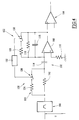
- the welding station shown in Figure 1 includes a generator transistor welding device 10 suitable for establishing a welding current between a welding electrode 12 and a mass 14 connected to the part to be welded.
- the welding generator 10 includes a converter 16 controlled in current or in voltage by control means 18.
- the control means 18 make it possible to control the converter for whether to supply the welding electrode 12 as a function of a control signal external.
- the frequency imposed on the generator by the means of command 18 is for example 50 kHz.
- Means for reducing spatter during welding are installed at the output of generator 10, upstream of the arc established between an electrode 12 and the mass 14.
- the welding station comprises means 20 for detection of the necking phenomenon or “pinch effect” phenomenon encountered at the end of the short circuit between the welding electrode 12 and the earth 14, as well as means 22 for reducing the welding current during the appearance of such a “pinch effect” phenomenon.
- the means 20 for detecting the phenomenon of "pinch effect" are suitable for measuring the arc voltage. This voltage is measured either at the output of generator 10, or advantageously closer to the arc. This measurement is carried out in particular by a wire of independent probe placed in the beam supplying the electrode. This thread is connected directly to electrode 14. Similarly, another wire is connected directly to the workpiece to measure its potential.
- the means 20 provide filtering of the measured voltage and a bypass of the voltage signal with respect to time.
- the signal thus derived is compared to a predetermined threshold and crossing this threshold causes the emission of a detection signal of the “pinch effect” phenomenon when the phenomenon occurs.
- the means 20 are connected to the control means 18 of the generator in order to drive these.
- the means 20 control the means 18 to stop the supply of the electrode 12 during the detection of the start of the “pinch effect” period. Food from generator 10 is not restored until after the short circuit is completed and establishment of a new arc between the electrode 12 and the part to be welded.
- the means 22 for reducing the welding current comprise means 24 for establishing, in series with the welding arc, of a high voltage determined in opposition to the direction of the current.
- These means 24 include a transformer 26 which operates in inductance outside the “pinch effect” periods, and which functions as a transformer during “pinch effect” periods.
- the electrode 12 is connected at the output of the generator 10 via of the power winding 26A.
- On the diagram of figure 1 is represented additionally a coil 12A corresponding to the inductance of the beam of cables supplying the arc.
- the second winding 26B ensuring the control of the winding of power 26A, is integrated into an excitation circuit 27.
- the control winding 26B comprises fifty turns.
- the excitation circuit 27 is adapted to temporarily impose, by through the control winding 26B, a high voltage in the power winding 26A, this voltage being in opposition to the direction of the current.
- a first end of the control winding 26B is linked to ground by a first voltage source 28.
- the voltage E 1 supplied by the first source 28 is fixed at 150 volts.
- the other end of the control winding 26B is connected to ground via a diode 30 and a second voltage source 32.
- the voltage E 2 supplied by the second source is fixed at 300 volts.
- a transistor 34 and a diode 36 are connected in series on a branch mounted in parallel with the control winding 26B.
- a transistor 38 is mounted in parallel with the voltage source 32 and diode 30. It connects the corresponding output of the control winding 26B to ground.
- the transistors are advantageously of the IGBT or MOS type.
- the controls of transistors 34 and 38 are connected to a circuit of pilot 40 adapted to control the conduction state of the two transistors.
- This control circuit 40 is connected to the means 20 for detecting the “pinch effect” phenomenon, so that the control of the conduction of transistors 34 and 38 is provided depending on the existence of the phenomenon pinch effect between the welding electrode 12 and the ground 14.
- control circuit 40 is directly connected to generator 10 to obtain representative information of the intensity delivered by it between the electrode 12 and the part to be solder.
- an auxiliary current source 42 is provided for debit a priming current, downstream of the power winding 26A, directly to the welding electrode 12.
- This auxiliary source 42 is suitable for re-striking the electric arc after completion of a short-circuit period before the generator 10 replenishes the circuit welding.
- the auxiliary source 42 supplies a constant current, for example of 20 A.
- the welding machine shown in Figure 1, works in the same way next.
- transistors 34 and 38 are blocked and the control means 18 control the converter 16, so that the welding generator 10 normally supplies the arc.
- the control means 18 control the converter 16, so that the welding generator 10 ceases to supply the arc.
- the transistor 34 is kept off and the transistor 38 is turned on.
- the diode 36 protects the transistor 34.
- a voltage E 1 established by the source 28, is then applied to the control winding 26B of the transformer.
- the power winding 26A then develops a voltage E ' 1 equal to the product of the voltage E 1 by the transformation ratio defined by the ratio of the number of turns of the two windings.
- the welding circuit is equivalent to a circuit RL subjected to a counter-electromotive force which tends to decrease the current established between the welding electrode 12 and the ground 14.
- R and L are respectively the resistance and the inductance of the welding circuit, that is to say of the coil 12A, and where n 1 and n 2 are the numbers of respective turns of the windings 26A and 26B.
- the control circuit 40 causes the transistor 38 to block, and switching on the transistor 34.
- the control winding 26B is then coasted and its current, except for losses, does not vary.
- transistor 34 is blocked while transistor 38 is also kept blocked.
- the control winding 26B then demagnetizes.
- the welding generator 10 is finally restarted via control means 18 for supplying the welding current during an arc period.
- the presence of the voltage source 32 and the diode 30 limits the voltage maximum that can be established at the terminals of the control winding 26B.
- the transistors 34 and 38 and the diode 36 are protected against any overvoltages that may arise between their terminals.
- the freewheeling of the control winding 26B avoids its demagnetization, because the current flowing in the control winding 26B would generate a current in the power winding 26A, which would tend to rapidly increase the welding current.
- Figure 2 is shown another embodiment of a station welding according to the invention in which the demagnetization of the winding control is provided by an additional winding provided in the transformer.
- the transformer used designated by reference 50, has a power winding 50A arranged between the output of the converter 16 and the welding electrode 12.
- control winding 50B and a winding demagnetization 50C.
- These two windings 50B and 50C connected in series are integrated into an excitation circuit 52 adapted to establish temporarily, in winding 50A, a strong tension in opposition with the direction of the welding current during the “pinch effect” phenomenon.
- the circuit 52 includes a single voltage source 54 connected between ground and the midpoint of the windings 50B and 50C. This source supplies a voltage E 3 equal to 150 V.
- the other terminal of the control winding 50B is connected to ground via a transistor 56.
- the transistors 56 and 60 are connected to the control circuit 40, itself connected to the means 20 for detecting the “pinch effect” phenomenon.
- the elements 54, 56, 58 and 60 are the counterparts, respectively, of elements 28, 38, 36 and 34 of the Figure 1. They magnetize the control winding 50B.
- the winding 50C is functionally the counterpart of the voltage source 32 and ensures both demagnetization of the winding 50B and protection of transistors 56 and 60.
- the welding station shown in Figure 2 operates in the following manner next.
- the transistors 56 and 60 are blocked and the control means 18 control the converter 16 to ensure the circulation of the welding current from the generator 10 through of the power winding 50A.
- the control means 18 interrupt the operation of the converter 16.
- the transistor 56 is turned on while the transistor 60 is kept blocked.
- a voltage E 3 supplied by the source 54 is established at the terminals of the control winding 50B.
- a voltage E ' 3 thus arises at the terminals of the power winding 50A, this voltage being opposite to the direction of flow of the welding current.
- transistor 56 is off while transistor 60 is on in conduction.
- the control winding 50B is then coasted through the branch made up of the diode 58 and the transistor 60.
- the transistor 60 After restoration of the electric arc, the transistor 60 is blocked from so that the control winding 50B gradually demagnetizes in particular through the demagnetization winding 50C.
- the diode 62 and the auxiliary winding 50C, at the terminals of which a difference of potential, ensure a limitation of the maximum voltage that can be established across the control winding 50B.
- Transistors 56 and 60 are thus protected, as well as the diode 58.
- Figure 3 of a welding station according to the invention differs from that of the figure 1 only by the structure of the excitation circuit of the winding of power.
- transformer 26 which works in inductance outside the "pinch effect” periods, and which works as a transformer during "pinch effect” periods.
- the transformer control winding 26B is integrated in an excitation circuit noted 70.
- a first loop formed by a transistor 72 and a diode 74 mounted in series is connected in parallel to the control winding 26B.
- a second loop formed by a transistor 76 and a diode 78 mounted in series is connected in parallel to the control winding 26B.
- the elements constituting the two loops are interchanged and have their terminals reversed.
- a voltage source 80 is connected to the midpoint of the two loops, that is to say between, on the one hand, the transistor 72 and the diode 74 and, on the other hand part, between transistor 76 and diode 78.
- the control winding 26B is thus arranged in a bridge consisting of two diodes and two transistors, the bridge being supplied by the voltage source 80.
- the transistors 72 and 76 are controlled by the circuit 40.
- the welding station of Figure 3 operates as follows.
- control means 18 stop the generator 10 which stops supplying the arc.
- the two transistors 72 and 76 are turned on.
- the tension established by the source 80 is then applied directly to the winding of command 26B.
- the welding current decreases rapidly, the circuit of welding being equivalent to an RL circuit subjected to a counterelectromotive force, as previously explained.
- the pilot circuit 40 causes the blocking of one of the transistors 72 and 76, the other being maintained in conduction.
- the control winding is then coasted to through the loop comprising the transistor held in conduction and the corresponding diode.
- the current of the control winding 26B is then substantially constant, the voltage source 80 then being non connected to the winding.
- transistor 72 or 76 still in conduction is blocked, causing demagnetization of the winding 26B control through diodes 74 and 78, source 80 and welding circuit.
- the excitation circuit 70 is of relatively simple structure since it requires only a single winding and a single voltage source.
- the energy consumption of the circuit is low since the voltage source provides energy during an operating phase of the circuit and partially recovers it during the other operating phase of the circuit.
- the charging circuit can be of a limited size since little energy is consumed by the excitation circuit.
- These means 20 are adapted to receive the input voltage U measured between the welding electrode 12 and the ground 14. They comprise in input a filter 100 adapted for satisfactory shaping of the signal.
- the means 20 comprise, at the output of the filter 100, a voltage diverter 102 monitoring at the output of a comparator 104. The latter is suitable for comparing the estimate of the derivative of the voltage at a predetermined threshold and thus detect the “pinch effect” phenomenon, when the value of the derivative of the voltage exceeds the predetermined threshold.
- the means 20 comprise means 106 for modifying the own derivation parameters to the branch circuit 102, during the short circuit period.
- the branch circuit 102 includes an operational amplifier 108 whose non-inverting output is connected to ground by a resistor 110 of 10 k ⁇ .
- the inverting terminal of the operational amplifier 108 is connected to the output of filter 100 by a resistor 112 of 0.82 k ⁇ mounted in series with a capacitor 114 of 22 nF.
- the feedback loop, connecting the output of the operational amplifier 108 at its inverting terminal, has in parallel a resistor 116 of 33 k ⁇ and a capacitor 118 4.7 nF.
- Resistors and capacitors 110 to 118 define first parameters for deriving the filtered voltage received at the input.
- these bypass parameters define a -3dB bandwidth ranging from 160 Hz to 55 kHz.
- the means 106 for modifying the derivation parameters include means 120 for modifying the input network connected to the terminal reverser of the operational amplifier 108 and the modification means 122 of the operational amplifier feedback loop impedance 108.
- the means 120 comprise, mounted in parallel on the resistor 112, a resistor auxiliary 1 k ⁇ connected in series with a controlled switch 126.
- the means 122 comprise, mounted in parallel on the resistor 116, a resistor 128 of 1 k ⁇ connected in series with a switch ordered 130.
- the switches 126 and 130 are controlled by means of control 132 adapted to cause the closing of switches 126 and 130 at the initial instant of detection of the short circuit. Switches 126 and 130 are kept closed for a period of between 100 ⁇ s and 2 ms, and advantageously substantially equal to 1 ms. When the switches 126 and 130 are closed, the bandwidth at -3dB of the branch circuit 102 ranges from 5.5 kHz to 100 kHz.
- control means 132 provide a modification of bypass parameters of bypass circuit 102.
- the second bypass parameters constituting modified derivation parameters are used.
- the first bypass parameters constituting the bypass parameters adapted for comparison to the predetermined threshold, are restored.
Landscapes
- Engineering & Computer Science (AREA)
- Physics & Mathematics (AREA)
- Plasma & Fusion (AREA)
- Mechanical Engineering (AREA)
- Arc Welding Control (AREA)
Abstract
Description
- des moyens de détection du phénomène de striction en fin de court-circuit entre l'électrode de soudage et la masse ; et
- des moyens de réduction du courant de soudage lors de l'existence du phénomène de striction.
- les moyens d'établissement d'une tension en opposition avec le courant de soudage comportent des moyens inductifs adaptés pour créer en série avec l'arc de soudage une force contre-électromotrice induite ;
- lesdits moyens inductifs comportent un transformateur, dont un enroulement de puissance est connecté en série avec l'arc de soudage, et dont un enroulement de commande est intégré dans le circuit d'excitation piloté par les moyens de détection du phénomène de «pinch effect» ;
- le circuit d'excitation est adapté pour magnétiser l'enroulement de commande, pendant au moins une partie des périodes de fonctionnement en court-circuit du poste de soudage, afin de créer dans l'enroulement de puissance, ladite force contre-électromotrice induite ;
- le circuit d'excitation comporte une source de tension et des moyens de commutation adaptés, pour assurer la magnétisation de l'enroulement de commande sous une première tension, lors de la détection du phénomène de striction afin de créer ladite force contre-électromotrice induite dans l'enroulement de puissance ;
- le circuit d'excitation comporte une seconde source de tension monté en série avec une diode, pour limiter la tension développée aux bornes de l'enroulement de commande ;
- ledit transformateur comporte en outre un enroulement auxiliaire couplé magnétiquement avec l'enroulement de puissance, et l'enroulement de commande, lequel enroulement auxiliaire est monté en série avec une diode dans le circuit d'excitation pour limiter la tension aux bornes de l'enroulement de commande ;
- le circuit d'excitation comporte, aux bornes de l'enroulement de commande, deux branches opposées montées en parallèle comportant chacune un organe de commutation à semi-conducteur et une diode montés en série, ainsi qu'un générateur de tension relié entre les transistors et diodes des deux branches ;
- le circuit d'excitation comporte des moyens de mise en roue libre de l'enroulement de commande avant l'achèvement de la période de fonctionnement en court-circuit du poste de soudage ;
- les moyens de détection du phénomène de striction en fin de court-circuit comportent un circuit dérivateur adapté pour estimer la dérivée de la tension établie entre l'électrode de soudage et la masse en fonction de paramètres de dérivation, et les moyens comportent des moyens de modification des paramètres de dérivation au cours de la période de court-circuit ;
- les moyens de modification des paramètres de dérivation sont adaptés pour modifier les paramètres de dérivation depuis l'instant initial de détection du court-circuit et maintenir les paramètres modifiés pendant une durée comprise entre 100 µs et 2 ms et notamment sensiblement égale à 1 ms ; et
- les moyens de détection du phénomène de striction comportent, pour la mesure de la tension d'arc, un premier fil de sonde indépendant relié directement à l'électrode, en aval du faisceau alimentant l'électrode depuis le générateur et un second fil de sonde relié directement à la pièce à souder.
- La figure 1 est une vue schématique d'un poste de soudage selon l'invention dont le générateur a une valeur d'inductance faible ;
- Les figures 2 et 3 sont des vues schématiques de variantes de réalisation du poste de la figure 1, et
- La figure 4 est une vue schématique de moyens de détection du phénomène de «pinch effect» pouvant être mis en oeuvre dans le poste de soudage des figures 1 à 3.
et E1' = E1 x n1 / n2
où R et L sont respectivement la résistance et l'inductance du circuit de soudage, c'est-à-dire de la bobine 12A, et
où n1 et n2 sont les nombres de spires respectifs des enroulements 26A et 26B. Le rapport de transformation est ici égal à 0,5, avec n1 = 25 spires et n2 = 50 spires.
Claims (13)
- Poste de soudage à l'arc pouvant fonctionner avec alternance de périodes d'arc et de périodes de court-circuit, du type comportant un générateur de courant de soudage (10) adapté pour établir un courant de soudage entre une électrode de soudage (12) et une masse (14) destinée à être reliée à la pièce à souder, lequel poste de soudage comporte :caractérisé en ce que les moyens (22) de réduction du courant de soudage comportent des moyens (24) d'établissement, en série avec l'arc de soudage, d'une tension en opposition avec le sens du courant de soudage, les moyens (24) comportant un circuit d'excitation (27 ; 52 ; 70) imposant ladite tension.des moyens (20) de détection du phénomène de striction en fin de court-circuit entre l'électrode de soudage (12) et la masse (14) ; etdes moyens (22) de réduction du courant de soudage lors de l'existence du phénomène de striction,
- Poste de soudage selon la revendication 1, caractérisé en ce que les moyens (24) d'établissement d'une tension en opposition avec le courant de soudage comportent des moyens inductifs (26 ; 50) adaptés pour créer en série avec l'arc de soudage une force contre-électromotrice induite.
- Poste de soudage selon la revendication 2, caractérisé en ce que lesdits moyens inductifs comportent un transformateur (26 ; 50), dont un enroulement de puissance (26A ; 50A) est connecté en série avec l'arc de soudage, et dont un enroulement de commande (26B ; 50B) est intégré dans le circuit d'excitation (27 ; 52 ; 70) piloté par les moyens (20) de détection du phénomène de «pinch effect».
- Poste de soudage selon la revendication 3, caractérisé en ce que le circuit d'excitation (27 ; 52 ; 70) est adapté pour magnétiser l'enroulement de commande (26B ; 50B), pendant au moins une partie des périodes de fonctionnement en court-circuit du poste de soudage, afin de créer dans l'enroulement de puissance (26A ; 50A), ladite force contre-électromotrice induite.
- Poste de soudage selon la revendication 4, caractérisé en ce que le circuit d'excitation (27 ; 52 ; 70) comporte une source de tension (28 ; 54 ; 80) et des moyens de commutation (38 ; 56 ; 72, 76) adaptés, pour assurer la magnétisation de l'enroulement de commande (26B) sous une première tension, lors de la détection du phénomène de striction afin de créer ladite force contre-électromotrice induite dans l'enroulement de puissance (26A).
- Poste de soudage selon la revendication 5, caractérisé en ce que le circuit d'excitation (27) comporte une seconde source de tension (32) monté en série avec une diode (30), pour limiter la tension développée aux bornes de l'enroulement de commande (26B).
- Poste de soudage selon la revendication 5, caractérisé en ce que ledit transformateur (50) comporte en outre un enroulement auxiliaire (50C) couplé magnétiquement avec l'enroulement de puissance (50A), et l'enroulement de commande (50B), lequel enroulement auxiliaire (50C) est monté en série avec une diode (62) dans le circuit d'excitation (52) pour limiter la tension aux bornes de l'enroulement de commande (50B).
- Poste de soudage selon la revendication 5, caractérisé en ce que le circuit d'excitation (70) comporte, aux bornes de l'enroulement de commande (26B), deux branches opposées montées en parallèle comportant chacune un organe de commutation à semi-conducteur (72, 76) et une diode (74, 78) montés en série, ainsi qu'un générateur de tension (80) relié entre les transistors (72, 76) et diodes (74, 76) des deux branches.
- Poste de soudage selon la revendication 5 ou 6, caractérisé en ce que le circuit d'excitation (27 ; 52 ; 70) comporte des moyens (34, 36 ; 58, 60 ; 72, 74) de mise en roue libre de l'enroulement de commande (26B ; 50B) avant l'achèvement de la période de fonctionnement en court-circuit du poste de soudage.
- Poste de soudage selon l'une quelconque des revendications précédentes, caractérisé en ce que les moyens (20) de détection du phénomène de striction en fin de court-circuit comportent un circuit dérivateur (102) adapté pour estimer la dérivée de la tension établie entre l'électrode de soudage (12) et la masse (14) en fonction de paramètres de dérivation, et en ce que les moyens (20) comportent des moyens (106) de modification des paramètres de dérivation au cours de la période de court-circuit.
- Poste de soudage selon la revendication 10, caractérisé en ce que les moyens de modification des paramètres de dérivation sont adaptés pour modifier les paramètres de dérivation depuis l'instant initial de détection du court-circuit et maintenir les paramètres modifiés pendant une durée comprise entre 100 µs et 2 ms et notamment sensiblement égale à 1 ms.
- Poste de soudage selon l'une quelconque des revendications précédentes, caractérisé en ce que les moyens (20) de détection du phénomène de striction comportent, pour la mesure de la tension d'arc, un premier fil de sonde indépendant relié directement à l'électrode (14), en aval du faisceau (12A) alimentant l'électrode (14) depuis le générateur (10) et un second fil de sonde relié directement à la pièce à souder.
- Utilisation d'un poste de soudage selon l'une des revendications 1 à 12 pour la mise en oeuvre d'un procédé de soudage MIG ou MAG.
Applications Claiming Priority (2)
| Application Number | Priority Date | Filing Date | Title |
|---|---|---|---|
| FR9908619 | 1999-07-05 | ||
| FR9908619A FR2795982B1 (fr) | 1999-07-05 | 1999-07-05 | Poste de soudage a l'arc avec alternance de periodes d'arc et de periodes de court-circuit |
Publications (1)
| Publication Number | Publication Date |
|---|---|
| EP1066910A1 true EP1066910A1 (fr) | 2001-01-10 |
Family
ID=9547691
Family Applications (1)
| Application Number | Title | Priority Date | Filing Date |
|---|---|---|---|
| EP00401802A Withdrawn EP1066910A1 (fr) | 1999-07-05 | 2000-06-23 | Poste de soudage à l'arc avec alternance de périodes d'arc et de périodes de court circuit. |
Country Status (2)
| Country | Link |
|---|---|
| EP (1) | EP1066910A1 (fr) |
| FR (1) | FR2795982B1 (fr) |
Citations (2)
| Publication number | Priority date | Publication date | Assignee | Title |
|---|---|---|---|---|
| DE1964245A1 (de) * | 1969-12-22 | 1971-08-12 | Linde Ag | Einrichtung zum Lichtbogenschweissen mit Konstantstromcharakteristik |
| FR2666261A1 (fr) * | 1990-09-04 | 1992-03-06 | Lincoln Electric Co | Systeme et procede de soudage a l'arc par court-circuit. |
-
1999
- 1999-07-05 FR FR9908619A patent/FR2795982B1/fr not_active Expired - Fee Related
-
2000
- 2000-06-23 EP EP00401802A patent/EP1066910A1/fr not_active Withdrawn
Patent Citations (2)
| Publication number | Priority date | Publication date | Assignee | Title |
|---|---|---|---|---|
| DE1964245A1 (de) * | 1969-12-22 | 1971-08-12 | Linde Ag | Einrichtung zum Lichtbogenschweissen mit Konstantstromcharakteristik |
| FR2666261A1 (fr) * | 1990-09-04 | 1992-03-06 | Lincoln Electric Co | Systeme et procede de soudage a l'arc par court-circuit. |
Non-Patent Citations (1)
| Title |
|---|
| MECKE ET AL.: "Schnelle elektrische Speisequellen für Schweisslichtbögen", ELEKTRIE, vol. 48, no. 4, 1994, berlin DE, pages 143 - 150, XP000456369 * |
Also Published As
| Publication number | Publication date |
|---|---|
| FR2795982A1 (fr) | 2001-01-12 |
| FR2795982B1 (fr) | 2001-09-14 |
Similar Documents
| Publication | Publication Date | Title |
|---|---|---|
| FR2486348A1 (fr) | Circuit d'alimentation de puissance pour une lampe de decharge a haute intensite | |
| EP0629036B1 (fr) | Dispositif pour la fourniture d'une tension à un circuit électronique, en particulier à un circuit électronique associé à un capteur d'intensité placé sur une ligne électrique | |
| FR2503604A1 (fr) | Soudeuse a l'arc par transfert de court-circuit | |
| FR1449718A (fr) | Appareil pour le soudage des goujons à l'arc électrique | |
| FR2666261A1 (fr) | Systeme et procede de soudage a l'arc par court-circuit. | |
| EP0034075B1 (fr) | Dispositif d'alimentation statique d'un électrofiltre de dépoussiérage électrostatique | |
| EP1009006A1 (fr) | Dispositif de commande standard d'un electro-aimant d'ouverture ou de fermeture d'un disjoncteur | |
| EP0722212A1 (fr) | Convertisseurs de tension bidirectionnels du type continu-continu et capteur de courant | |
| CH628423A5 (fr) | Circuit electrique pour l'allumage d'un detonateur. | |
| FR2811490A1 (fr) | Unite de commande de tension pour un generateur de courant alternatif vehiculaire | |
| EP0567408B1 (fr) | Dispositif d'alimentation de lampes à décharge et projecteur de véhicule utilisant un tel dispositif | |
| FR2532487A1 (fr) | Regulateur pour charge de batterie d'accumulateurs par alternateur a aimant permanent | |
| CH684828A5 (fr) | Générateur d'impulsions pour usiner par électro-érosion. | |
| CH689256A5 (fr) | Ensemble d'alimentation électrique pour traitement par décharges dans une machine d'électroérosion. | |
| FR2795982A1 (fr) | Poste de soudage a l'arc avec alternance de periodes d'arc et de periodes de court-circuit | |
| EP1493522B1 (fr) | Dispositif d'usinage par électroérosion | |
| FR2819353A1 (fr) | Regulateur et procede de production d'energie pour un vehicule | |
| EP1063043B1 (fr) | Procédé et dispositif pour l'usinage par électroérosion | |
| EP1320919A1 (fr) | Limitation du mode continu d'un convertisseur de puissance | |
| EP0064450B1 (fr) | Procédé et dispositif autoadaptatif d'amorçage d'un triac | |
| FR2481530A1 (fr) | Procede et dispositif de production d'impulsions electriques pour le pompage d'un laser | |
| EP0021867B1 (fr) | Dispositif d'alimentation à découpage régulé contre les variations de tension d'entrée et de puissance de sortie, notamment pour récepteur de télévision | |
| CA2187662C (fr) | Circuit d'alimentation d'une bobine d'excitation d'un electro-aimant | |
| EP0143048B1 (fr) | Convertisseur continu-continu à inductance de charge commutée | |
| FR2977818A1 (fr) | Procede de soudage a l'arc avec electrode consommable |
Legal Events
| Date | Code | Title | Description |
|---|---|---|---|
| PUAI | Public reference made under article 153(3) epc to a published international application that has entered the european phase |
Free format text: ORIGINAL CODE: 0009012 |
|
| AK | Designated contracting states |
Kind code of ref document: A1 Designated state(s): AT BE CH CY DE DK ES FI FR GB GR IE IT LI LU MC NL PT SE |
|
| AX | Request for extension of the european patent |
Free format text: AL;LT;LV;MK;RO;SI |
|
| RAP1 | Party data changed (applicant data changed or rights of an application transferred) |
Owner name: L'AIR LIQUIDE, SOCIETE ANONYME POUR L'ETUDE ET L' Owner name: LA SOUDURE AUTOGENE FRANCAISE |
|
| 17P | Request for examination filed |
Effective date: 20010710 |
|
| AKX | Designation fees paid |
Free format text: AT BE CH CY DE DK ES FI FR GB GR IE IT LI LU MC NL PT SE |
|
| RAP1 | Party data changed (applicant data changed or rights of an application transferred) |
Owner name: L'AIR LIQUIDE, S.A. A DIRECTOIRE ET CONSEIL DE SU Owner name: LA SOUDURE AUTOGENE FRANCAISE |
|
| GRAP | Despatch of communication of intention to grant a patent |
Free format text: ORIGINAL CODE: EPIDOSNIGR1 |
|
| STAA | Information on the status of an ep patent application or granted ep patent |
Free format text: STATUS: THE APPLICATION IS DEEMED TO BE WITHDRAWN |
|
| 18D | Application deemed to be withdrawn |
Effective date: 20051012 |