EP1066066B1 - Closed chest intra-aortic balloon based ventricular assist device - Google Patents
Closed chest intra-aortic balloon based ventricular assist device Download PDFInfo
- Publication number
- EP1066066B1 EP1066066B1 EP19990912354 EP99912354A EP1066066B1 EP 1066066 B1 EP1066066 B1 EP 1066066B1 EP 19990912354 EP19990912354 EP 19990912354 EP 99912354 A EP99912354 A EP 99912354A EP 1066066 B1 EP1066066 B1 EP 1066066B1
- Authority
- EP
- European Patent Office
- Prior art keywords
- pumping chamber
- blood
- pumping
- chamber
- balloon membrane
- Prior art date
- Legal status (The legal status is an assumption and is not a legal conclusion. Google has not performed a legal analysis and makes no representation as to the accuracy of the status listed.)
- Expired - Lifetime
Links
Images


Classifications
-
- A—HUMAN NECESSITIES
- A61—MEDICAL OR VETERINARY SCIENCE; HYGIENE
- A61M—DEVICES FOR INTRODUCING MEDIA INTO, OR ONTO, THE BODY; DEVICES FOR TRANSDUCING BODY MEDIA OR FOR TAKING MEDIA FROM THE BODY; DEVICES FOR PRODUCING OR ENDING SLEEP OR STUPOR
- A61M25/00—Catheters; Hollow probes
- A61M25/0067—Catheters; Hollow probes characterised by the distal end, e.g. tips
- A61M25/0074—Dynamic characteristics of the catheter tip, e.g. openable, closable, expandable or deformable
- A61M25/0075—Valve means
-
- A—HUMAN NECESSITIES
- A61—MEDICAL OR VETERINARY SCIENCE; HYGIENE
- A61M—DEVICES FOR INTRODUCING MEDIA INTO, OR ONTO, THE BODY; DEVICES FOR TRANSDUCING BODY MEDIA OR FOR TAKING MEDIA FROM THE BODY; DEVICES FOR PRODUCING OR ENDING SLEEP OR STUPOR
- A61M60/00—Blood pumps; Devices for mechanical circulatory actuation; Balloon pumps for circulatory assistance
- A61M60/10—Location thereof with respect to the patient's body
- A61M60/122—Implantable pumps or pumping devices, i.e. the blood being pumped inside the patient's body
- A61M60/126—Implantable pumps or pumping devices, i.e. the blood being pumped inside the patient's body implantable via, into, inside, in line, branching on, or around a blood vessel
- A61M60/135—Implantable pumps or pumping devices, i.e. the blood being pumped inside the patient's body implantable via, into, inside, in line, branching on, or around a blood vessel inside a blood vessel, e.g. using grafting
- A61M60/139—Implantable pumps or pumping devices, i.e. the blood being pumped inside the patient's body implantable via, into, inside, in line, branching on, or around a blood vessel inside a blood vessel, e.g. using grafting inside the aorta, e.g. intra-aortic balloon pumps
-
- A—HUMAN NECESSITIES
- A61—MEDICAL OR VETERINARY SCIENCE; HYGIENE
- A61M—DEVICES FOR INTRODUCING MEDIA INTO, OR ONTO, THE BODY; DEVICES FOR TRANSDUCING BODY MEDIA OR FOR TAKING MEDIA FROM THE BODY; DEVICES FOR PRODUCING OR ENDING SLEEP OR STUPOR
- A61M60/00—Blood pumps; Devices for mechanical circulatory actuation; Balloon pumps for circulatory assistance
- A61M60/20—Type thereof
- A61M60/295—Balloon pumps for circulatory assistance
-
- A—HUMAN NECESSITIES
- A61—MEDICAL OR VETERINARY SCIENCE; HYGIENE
- A61M—DEVICES FOR INTRODUCING MEDIA INTO, OR ONTO, THE BODY; DEVICES FOR TRANSDUCING BODY MEDIA OR FOR TAKING MEDIA FROM THE BODY; DEVICES FOR PRODUCING OR ENDING SLEEP OR STUPOR
- A61M60/00—Blood pumps; Devices for mechanical circulatory actuation; Balloon pumps for circulatory assistance
- A61M60/40—Details relating to driving
- A61M60/497—Details relating to driving for balloon pumps for circulatory assistance
-
- A—HUMAN NECESSITIES
- A61—MEDICAL OR VETERINARY SCIENCE; HYGIENE
- A61M—DEVICES FOR INTRODUCING MEDIA INTO, OR ONTO, THE BODY; DEVICES FOR TRANSDUCING BODY MEDIA OR FOR TAKING MEDIA FROM THE BODY; DEVICES FOR PRODUCING OR ENDING SLEEP OR STUPOR
- A61M60/00—Blood pumps; Devices for mechanical circulatory actuation; Balloon pumps for circulatory assistance
- A61M60/80—Constructional details other than related to driving
- A61M60/855—Constructional details other than related to driving of implantable pumps or pumping devices
- A61M60/865—Devices for guiding or inserting pumps or pumping devices into the patient's body
-
- A—HUMAN NECESSITIES
- A61—MEDICAL OR VETERINARY SCIENCE; HYGIENE
- A61M—DEVICES FOR INTRODUCING MEDIA INTO, OR ONTO, THE BODY; DEVICES FOR TRANSDUCING BODY MEDIA OR FOR TAKING MEDIA FROM THE BODY; DEVICES FOR PRODUCING OR ENDING SLEEP OR STUPOR
- A61M60/00—Blood pumps; Devices for mechanical circulatory actuation; Balloon pumps for circulatory assistance
- A61M60/80—Constructional details other than related to driving
- A61M60/855—Constructional details other than related to driving of implantable pumps or pumping devices
- A61M60/89—Valves
- A61M60/894—Passive valves, i.e. valves actuated by the blood
- A61M60/896—Passive valves, i.e. valves actuated by the blood having flexible or resilient parts, e.g. flap valves
-
- A—HUMAN NECESSITIES
- A61—MEDICAL OR VETERINARY SCIENCE; HYGIENE
- A61M—DEVICES FOR INTRODUCING MEDIA INTO, OR ONTO, THE BODY; DEVICES FOR TRANSDUCING BODY MEDIA OR FOR TAKING MEDIA FROM THE BODY; DEVICES FOR PRODUCING OR ENDING SLEEP OR STUPOR
- A61M60/00—Blood pumps; Devices for mechanical circulatory actuation; Balloon pumps for circulatory assistance
- A61M60/20—Type thereof
- A61M60/247—Positive displacement blood pumps
- A61M60/253—Positive displacement blood pumps including a displacement member directly acting on the blood
- A61M60/268—Positive displacement blood pumps including a displacement member directly acting on the blood the displacement member being flexible, e.g. membranes, diaphragms or bladders
- A61M60/274—Positive displacement blood pumps including a displacement member directly acting on the blood the displacement member being flexible, e.g. membranes, diaphragms or bladders the inlet and outlet being the same, e.g. para-aortic counter-pulsation blood pumps
Definitions
- the present invention relates generally to devices for augmenting cardiac output, and specifically to intra-aortic cardiac assist pumps.
- Intra-aortic and intra-ventricular cardiac assist devices are well known in the art. These devices are generally used to reduce the heart's work load after insult or surgery. They may also be used to increase blood flow from the left ventricle of the heart into the aorta in cases of insufficient cardiac output due, for example, to acute or chronic heart ailments or to interference with normal cardiac function during surgery.
- Cardiac assist devices fall into two basic categories, those comprising an external pumping chamber which remains outside the body during the entire course of the therapy (extracorporeal) and those comprising an internal pumping chamber which remains inside of the body (intracorporeal).
- an internal pumping chamber is that it requires extensive surgery for implantation and removal of the device.
- U.S. Patent 4,014,317 describes a cardiocirculatory assist cannula with a an external balloon pump and cardiac pacing electrode.
- the cannula is inserted percutaneously through the aorta so that its distal end is inside the left ventricle of the heart.
- inlet valves on the cannula inside the left ventricle remain open, and the contraction of the ventricle forces blood to flow into the cannula.
- the blood flows out, into the aorta, through one or more outlet valves along the cannula downstream from the inlet valve.
- a gas-filled chamber similar in function to an Intra-Aortic Balloon Pump (IABP) is connected to the cannula external to the patient and downstream of the outlet valves.
- the balloon is typically inflated during diastole and deflated during systole, to assist in perfusion of the coronary arteries.
- the cannula has a long and narrow shape which presents a significant blood flow restriction, and thus, limits the effective stroke volume of the device. Accordingly, the device is of limited usefulness in augmenting the blood output of a weakened or failing heart.
- U.S. Patent 4,906,229 describes a high-frequency transvalvular axisymmetric external blood pump.
- the pump includes a small internal volume in a stiff barrel, which may be alternately expanded and reduced by pneumatic or hydraulic pressure which is exerted via a flexible membrane radially surrounding the volume.
- the volume has intake and outlet ends, with one-way axial valves at both of the ends, so that blood can flow only from the heart into the aorta.
- the pump is connected via the one-way intake valve to a cannula, which is inserted into the left ventricle of the heart through the aortic valve. When the internal volume is expanded, blood flows into the pump from the ventricle.
- This pump is designed to operate at a frequency of 600 to 1,000 cycles per minute. Since the stroke volume of the pump is typically only about 3-5 cc, these high cycle rates are needed in order to provide adequate perfusion.
- a major drawback of the prior art extracorporeal intra-aortic cardiac assist devices involves an inherent design limitation of said devices.
- the prior art extra-corporeal intra-aortic cardiac assist devices pump blood out of the left ventricle, through a cannula, and into a downstream portion of the artery.
- cannulae are generally designed large enough to accommodate only 20-40 cc of blood per heart cycle. The average patient, however, requires approximately 80-100 cc of blood per heart cycle for full blood flow support.
- cardiac assist devices are also categorized according to their pump drives, which are either continuous or pulsatile flow.
- pump drives which are either continuous or pulsatile flow.
- a cannula containing a special, miniature rotor pump mechanism is inserted into the aorta.
- the pump is driven by a drive unit outside the body, to pump blood continuously from the aorta into the rest of the arterial system, thereby supplementing to some degree the heart's natural output rate.
- a system of this type is similarly described in U.S. Patent 5,092,844.
- a drawback of this system is that the outer diameter of the pump, and accordingly the pump's output, is limited due to the need for insertion through the femoral artery.
- IABP Intra-Aortic Balloon Pump
- a catheter having an inflatable balloon at its distal end, which is inserted through an artery into the aorta.
- the balloon is alternately inflated and deflated by an external pump drive, so as to alternately increase and decrease blood pressure in the aorta, in counter phase with the beating of the heart, in order to assist the left ventricle in propelling blood into the arterial system.
- the Intra-Aortic Balloon (IAB) catheter is a popular cardiac assist device because it can be inserted percutaneously, and therefore, avoids the major surgery associated with implantation and removal of an internal ventricular assist device-
- the IABP provides only limited augmentation of the heart's natural, unassisted output, and is not adequate for overcoming a major heart failure.
- U.S. Patent No. 4, 906, 229 discloses a high-frequency transvascular blood pump for temporary cardiac assist.
- the intake of the pump is connected to a cannula which is inserted into the ventricular cavity through the aortic valve, and which has an intake opening at its distal end.
- the pump itself consists of a stiff barrel whose interior volume can be alternately reduced and expanded by a flexible membrane controlled by pneumatic or hydraulic pressure from an extracorporeal location through a percutaneously inserted lumen.
- GB-A 1 526 099 discloses a surgically implantable semi-biological internal circuit pumping device comprising a balloon catheter disposed within a rigid pumping chamber.
- the invention is a closed chest intra-aortic balloon catheter based ventricular assist device comprising an intra-aortic balloon (IAB) catheter and a pumping chamber having a smaller diameter portion and a more proximal larger diameter portion.
- the IAB catheter balloon membrane is disposed within the larger diameter portion.
- the entire device is inserted percutaneously into the aorta of a patient such that the tip of the IAB catheter is just distal to the left subclavian artery and the distal end of the smaller diameter portion is in the left ventricle.
- the smaller diameter portion has an intake valve at its distal end which acts as a one-way valve allowing blood to flow into the lumen of the pumping chamber but not out of it.
- the pumping chamber has one or more outlet valves.
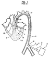
- FIG 1 illustrates a longitudinal cross section of an inserted prior art cardiac assist pump, generally designated 10, comprising an external pump 20 and a cannula 30 having a proximal end 31, a distal end 32, an intake valve 40, outlet valves 50, and a lumen 51.
- the cannula 30 is inserted percutaneously, through an incision 61 in the peripheral artery 60, or another suitable artery such as the femoral artery, and passed upstream through aorta 70 and aortic valve 140 into the left ventricle 80 of heart 90.
- the method of insertion is substantially similar to methods for insertion of other types of cardiac cannulae known in the art.
- the length of the cannula 30 is approximately 60 cm, which is generally sufficient to ensure that when the distal end of the cannula 30 is positioned in the left ventricle 80 the proximal end of the cannula 30 remains outside the body of the patient, adjacent to the incision 61.
- the cannula 30 may be inserted surgically through a suitable incision elsewhere in the arterial system.
- the pump 20 creates a pressure differential in the cannula 30, and as a result, the intake valve 40, located at the distal end 32 of the cannula 30, is opened, and blood flows from the left ventricle 80 into lumen 51. Outlet valves 50 are kept closed while the blood fills the lumen 51.
- the pump 20 creates an opposite pressure differential in the chamber, and as a result, the intake valve 40 is closed and the outlet valves 50 are opened and the blood is forced out of the lumen 51 and into the aorta 70.
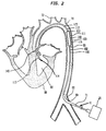
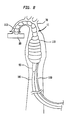
- FIG 2 illustrates a longitudinal cross section of the present invention, generally designated 11, inserted into the aorta 70 of a patient.
- the present invention 11 comprises an Intra-Aortic Balloon (IAB) catheter 100 and a pumping chamber 110 having outlet valves 115.
- the pumping chamber 110 comprises a larger tube chamber portion 111, having a proximal end 99, and a smaller tube cannula portion 112, having a distal end 113.
- distal refers to a location closer to the heart.
- a leaflet intake valve 114, or other suitable intake valve is attached to the distal end 113 of the smaller tube cannula portion 112 of the pumping chamber 110.
- the IAB catheter 100 comprises generally a balloon membrane 101, an outer tube 102, a tip 103, and an external pump 20.
- the IAB catheter 100 is generally inserted percutaneously into the aorta 70 through an optional insertion sheath 71, and the tip 103 is placed just distal to the left subclavian artery 72.
- the external pump 20 shuttles a non-blood material, such as gas, back and forth in the outer tube 102 causing the ballon membrane 101 to inflate and deflate rapidly.
- the balloon membrane 101 is slidingly disposed within the larger tube chamber portion 111 of the pumping chamber 110.
- the proximal end 99 of the larger tube chamber portion 111 is slidingly attached to the outer tube 102 of the IAB catheter 100 such that blood cannot escape through said proximal end 99.
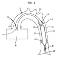
- FIGS 3 and 4 illustrate a longitudinal cross section of the pumping chamber 110 and a distal portion of the IAB catheter 100 inserted into the aorta 70 of a patient.
- FIG 3 illustrates the means by which blood is forced into the smaller tube cannula portion 112.
- the balloon membrane 101 is in a deflated state, and as a result, the pressure in the pumping chamber 110 is lower than the pressure in the aorta 70, and preferably, is close to that in the left ventricle 80.
- the pressure differential causes the leaflet intake valve 114 to open and allow blood to flow into the distal end 113 of the smaller tube cannula portion 112.
- Lower pressure in the pumping chamber 110 also causes the outlet valves 115 to close, thereby, preventing any blood from escaping through said outlet valves 115 into the aorta 70.
- the aortic valve 140 opens in concert with the outlet valves 115.
- the diameter of the smaller tube cannula portion 112 may be made larger so as to accommodate the entire blood flow.
- the smaller tube cannula portion 112 and the annular area between the balloon membrane 101 and the larger tube chamber portion 111 are the only blood containing portions of the present invention 11.
- the IAB catheter 100 may be considered the non-blood containing portion of the present invention 11.
- FIG 4 illustrates the means by which the blood is forced out of the pumping chamber 110.
- the balloon membrane 101 is inflated causing the pressure in the pumping chamber 110 to increase.
- the intake valve 114 is forced shut by blood attempting to reenter the left ventricle 80, and the outlet valves 115 are forced open allowing blood in both the smaller tube cannula portion 112 and the larger tube chamber portion 111 to flow into the aorta 70.
- outlet valves 115 may be located throughout the pumping chamber 110.
- the present invention li, with minor variations, is anticipated for use as a right ventricular assist device as well.
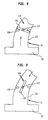
- FIG 5 illustrates an alternate embodiment of the intake valve 114.
- the intake valve 114 comprises a disk 116 that is rotatably attached to the smaller tube cannula portion 112 by means of a pin 117.
- the disk 116 rotates to its transverse closed position and stays there as a result of stoppers 118, preventing blood from reentering the left ventricle 80.
- the disk 116 spins back to its longitudinal open position and allows the blood to flow into the pumping chamber 110. Note that different forms of intake and outlet valves are anticipated.
- the IAB catheter 100 and the pumping chamber 110 are inserted percutaneously in series or as one unit.
- the method for inserting an IAB catheter is well known in the art.
- the preferred embodiment of the pumping chamber 110, capable of being inserted percutaneously, is illustrated in FIGS 7-8.
- the pumping chamber 110 must be able to withstand the high pressures generated in the aorta 70, as a result of the deflation of the balloon membrane 101, during actual blood pumping, and yet it must also be flexible enough during insertion to be capable of being advanced into the aorta 70.
- FIG 7 illustrates a longitudinal cross section of the fluid-filled pumping chamber 110, disposed about the balloon membrane 101 of the IAB catheter 100, which demonstrates these properties.
- the IAB catheter 100 is percutaneously inserted such that the tip 103 is just proximal the left subclavian artery 72.
- the pumping chamber 110 has a pump tube 118, having a distal end 113 and a proximal end 99, and a fluid delivery tube 119 attached to the pump tube 118.
- the pumping chamber 110 is disposed about a proximal end 126 of the IAB catheter 100 and advanced into the aorta 70 such that distal end 113 of the pump tube 118 enters the left ventricle 80.
- the proximal end 99 of the pump tube 118 is slidingly attached to the outer tube 102 of the IAB catheter 100 such that blood cannot escape through said proximal end 99.
- a lumen 120 extends the entire length of the fluid delivery tube 119 and runs in a helical or other similar manner around the pump tube 118. Once positioned in the aorta 70 the lumen 120 is filled with fluid.
- the fluid-filled lumen 120 increases the rigidity of the pumping chamber 110 such that it is capable of withstanding pressures generated in the aorta 70 during deflation of the balloon membrane 101.
- the fluid is pumped out of the lumen 120 and the pumping chamber 110 is once again supple and small enough to be removed from the aorta 70 percutaneously.
- FIG 8 illustrates a perspective view of the fluid-filled pumping chamber 110 illustrated in FIG 7.
- fluid-filled pockets or fluid-filled surface sectors may be used.
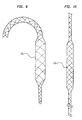
- FIG 9 illustrates an alternate pumping chamber 110 made from intercoiled wires covered with an elastic leak proof or other suitable material, similar to expandable stents on the market, and has the property that when pulled or stretched its cross sectional diameter decreases. Insertion of the closed chest IAB-based ventricular assist device 11 incorporating the pumping chamber 110, as illustrated in FIG 9, comprises the following steps. The IAB catheter 100 is first inserted into the aorta 70. Next, the pumping chamber 110, in a stretched state, is advanced over the IAB catheter 100 into the aorta 70.
- FIG 9 illustrates a plain view of the pumping chamber 110 in its unstretched state.
- FIG 10 illustrates a plain view of the pumping chamber 110 in its stretched state.
- the pumping chamber 110 is attached to the IAB catheter 100 in the same manner as the pumping chamber 110 illustrated in FIG 2.
- the pumping chamber 110 is stretched to its smaller diameter stretched state and is then removed percutaneously. After removal of the pumping chamber 110 the IAB catheter 100 is removed percutaneously.
- the pumping chamber 110 is inserted into and removed from the patient in a manner similar to other expandable stents on the market, such as the Corvita stent (produced by Corvita Corp, Miami, FL).
- the IAB catheter 100 may be inserted after insertion of the pumping chamber 110.
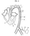
- FIG 11 illustrates a longitudinal cross section of an alternate embodiment of the present invention 11 inserted into the aorta 70 comprising a cannula 160 having a gas tube portion 128, a proximal end 126, and a pumping chamber 110 having a distal end 113 and a diaphragm 127.
- the proximal end 126 of the gas tube portion 128 is connected to an external non-blood pump 20.
- the distal end of the pumping chamber 110 is inserted into the left ventricle 80 of the heart 90-Similar to the first embodiment of the present invention 11, blood flow is limited only to the pumping chamber 110.
- the pumping chamber 110 is the only blood containing portion of the present invention 11.
- the gas tube portion 128 is filled with a non-blood material, such as helium.
- the gas tube portion 128 basically replaces the IAB catheter 100, as illustrated in FIG 2, as the non-blood containing portion of the present invention 11.
- the diameter of the gas tube portion 128 may be made smaller than the diameter of the pumping chamber 110. Reduction of the diameter of the gas tube portion 128 allows for more blood flow around the gas tube portion 128 and thus improves circulation in the patient during the procedure.
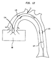
- FIG 12 illustrates a longitudinal cross section of a distal portion of the alternate embodiment illustrated in FIG 11 with the diaphragm 127 in a blood intake state.
Abstract
Description
- The present invention relates generally to devices for augmenting cardiac output, and specifically to intra-aortic cardiac assist pumps.
- Intra-aortic and intra-ventricular cardiac assist devices are well known in the art. These devices are generally used to reduce the heart's work load after insult or surgery. They may also be used to increase blood flow from the left ventricle of the heart into the aorta in cases of insufficient cardiac output due, for example, to acute or chronic heart ailments or to interference with normal cardiac function during surgery.
- Cardiac assist devices fall into two basic categories, those comprising an external pumping chamber which remains outside the body during the entire course of the therapy (extracorporeal) and those comprising an internal pumping chamber which remains inside of the body (intracorporeal). One major drawback to an internal pumping chamber is that it requires extensive surgery for implantation and removal of the device.
- Devices with external pumping chambers also have a number of drawbacks. U.S. Patent 4,014,317, describes a cardiocirculatory assist cannula with a an external balloon pump and cardiac pacing electrode. The cannula is inserted percutaneously through the aorta so that its distal end is inside the left ventricle of the heart. During systole, inlet valves on the cannula inside the left ventricle remain open, and the contraction of the ventricle forces blood to flow into the cannula. Then, during diastole, the blood flows out, into the aorta, through one or more outlet valves along the cannula downstream from the inlet valve. A gas-filled chamber, similar in function to an Intra-Aortic Balloon Pump (IABP), is connected to the cannula external to the patient and downstream of the outlet valves. The balloon is typically inflated during diastole and deflated during systole, to assist in perfusion of the coronary arteries. The cannula has a long and narrow shape which presents a significant blood flow restriction, and thus, limits the effective stroke volume of the device.
Accordingly, the device is of limited usefulness in augmenting the blood output of a weakened or failing heart. - U.S. Patent 4,906,229 describes a high-frequency transvalvular axisymmetric external blood pump. The pump includes a small internal volume in a stiff barrel, which may be alternately expanded and reduced by pneumatic or hydraulic pressure which is exerted via a flexible membrane radially surrounding the volume. The volume has intake and outlet ends, with one-way axial valves at both of the ends, so that blood can flow only from the heart into the aorta. The pump is connected via the one-way intake valve to a cannula, which is inserted into the left ventricle of the heart through the aortic valve. When the internal volume is expanded, blood flows into the pump from the ventricle. The volume is then reduced, and the blood is ejected into the aorta through the outlet end. This pump is designed to operate at a frequency of 600 to 1,000 cycles per minute. Since the stroke volume of the pump is typically only about 3-5 cc, these high cycle rates are needed in order to provide adequate perfusion.
- A major drawback of the prior art extracorporeal intra-aortic cardiac assist devices involves an inherent design limitation of said devices. The prior art extra-corporeal intra-aortic cardiac assist devices pump blood out of the left ventricle, through a cannula, and into a downstream portion of the artery. There is a desire to make the inner diameter of the cannula as large as possible so as to allow for the greatest possible blood flow rate through said cannula. There is also a desire, however, to make the outer diameter of the cannula as small as possible to ease its insertion into the artery and so as not to substantially reduce the blood flow in the artery around the cannula. As a result of these competing design goals cannulae are generally designed large enough to accommodate only 20-40 cc of blood per heart cycle. The average patient, however, requires approximately 80-100 cc of blood per heart cycle for full blood flow support.
- Aside from the internal / external pumping chamber distinction, cardiac assist devices are also categorized according to their pump drives, which are either continuous or pulsatile flow. In the Hemopump Cardiac Assist System, distributed by Johnson & Johnson Interventional Systems, a cannula containing a special, miniature rotor pump mechanism is inserted into the aorta. The pump is driven by a drive unit outside the body, to pump blood continuously from the aorta into the rest of the arterial system, thereby supplementing to some degree the heart's natural output rate. A system of this type is similarly described in U.S. Patent 5,092,844. A drawback of this system is that the outer diameter of the pump, and accordingly the pump's output, is limited due to the need for insertion through the femoral artery. A further drawback of this system, and of continuous-flow devices in general, concerns the belief that pulsatile pumps provide more effective long-term support than continuous-flow devices since they approximate more closely the natural pump action of the heart.
- One of the best-known and most widely-used intra-aortic pump systems is the Intra-Aortic Balloon Pump (IABP), comprising a catheter, having an inflatable balloon at its distal end, which is inserted through an artery into the aorta. The balloon is alternately inflated and deflated by an external pump drive, so as to alternately increase and decrease blood pressure in the aorta, in counter phase with the beating of the heart, in order to assist the left ventricle in propelling blood into the arterial system. The Intra-Aortic Balloon (IAB) catheter is a popular cardiac assist device because it can be inserted percutaneously, and therefore, avoids the major surgery associated with implantation and removal of an internal ventricular assist device- The IABP, however, provides only limited augmentation of the heart's natural, unassisted output, and is not adequate for overcoming a major heart failure.
- U.S. Patent No. 4, 906, 229, issued to Wampler, discloses a high-frequency transvascular blood pump for temporary cardiac assist. The intake of the pump is connected to a cannula which is inserted into the ventricular cavity through the aortic valve, and which has an intake opening at its distal end. The pump itself consists of a stiff barrel whose interior volume can be alternately reduced and expanded by a flexible membrane controlled by pneumatic or hydraulic pressure from an extracorporeal location through a percutaneously inserted lumen.
- GB-A 1 526 099 discloses a surgically implantable semi-biological internal circuit pumping device comprising a balloon catheter disposed within a rigid pumping chamber.
- While these devices may be suitable for the particular purpose employed, or for general use, they would not be as suitable for the purposes of the present invention as disclosed hereafter.
- Accordingly, it is an object of the invention to produce a cardiac assist device which is capable of overcoming heart failure by providing full blood flow support.
- It is another object of the invention to produce a cardiac assist device which can be inserted percutaneously or through a limited cut-down procedure, and therefore, does not require extensive thoracic surgery for implantation and removal.
- It is a further object of the invention to produce a cardiac assist device which produces a pulsatile blood flow which more closely approximates the natural pump action of the heart.
- It is a still further object of the invention to produce a cardiac assist device which does not substantially reduce blood flow in the occupied artery.
- The invention is as defined in the appended set of claims.
- The invention is a closed chest intra-aortic balloon catheter based ventricular assist device comprising an intra-aortic balloon (IAB) catheter and a pumping chamber having a smaller diameter portion and a more proximal larger diameter portion. The IAB catheter balloon membrane is disposed within the larger diameter portion. The entire device is inserted percutaneously into the aorta of a patient such that the tip of the IAB catheter is just distal to the left subclavian artery and the distal end of the smaller diameter portion is in the left ventricle. The smaller diameter portion has an intake valve at its distal end which acts as a one-way valve allowing blood to flow into the lumen of the pumping chamber but not out of it. The pumping chamber has one or more outlet valves. As the balloon membrane deflates, pressure in the pumping chamber drops below that in the left ventricle, and as a result, blood flows into the pumping chamber. As the balloon membrane inflates, increased pressure in the pumping chamber forces the intake valve shut and forces blood through the outlet valves into the aorta. The pumping chamber becomes substantially rigid after insertion so as to withstand arterial blood pressure.
- To the accomplishment of the above and related objects the invention may be embodied in the form illustrated in the accompanying drawings. Attention is called to the fact, however, that the drawings are illustrative only. Variations are contemplated as being part of the invention, limited only by the scope of the claims.
- In the drawings, like elements are depicted by like reference numerals. The drawings are briefly described as follows.
- FIG 1 is a longitudinal cross section of a prior art cardiac assist pump system inserted into the aorta of a patient.
- FIG 2 is longitudinal cross section of the present invention, a closed chest IAB-based ventricular assist device, inserted into the aorta and left ventricle of a patient.
- FIG 3 is a longitudinal cross section of a distal portion of the inserted closed chest IAB-based ventricular assist device, illustrated in FIG 2, with the balloon membrane in a deflated state.
- FIG 4 is a longitudinal cross section of a distal portion of the inserted closed chest IAB-based ventricular assist device, illustrated in FIG 2, with the balloon membrane in an inflated state.
- FIG 5 is a longitudinal cross section of a distal end of a closed chest IAB-based ventricular assist device with an alternate embodiment of the intake valve in a transverse closed state.
- FIG 6 is a longitudinal cross section of a distal end cf a closed chest IAB-based ventricular assist device with an alternate embodiment of the intake valve in a longitudinal open state.
- FIG 7 is a longitudinal cross section of a fluid-filled pumping chamber disposed about an IAB catheter balloon membrane and inserted into the aorta and left ventricle of a patient.
- FIG 8 illustrates a perspective view of the fluid-filled pumping chamber illustrated in FIG 7.
- FIG 9 is a plain view of a third embodiment of the pumping chamber in its unstretched larger diameter state.
- FIG 10 is a plain view of the third embodiment of the pumping chamber is its stretched smaller diameter state.
- FIG 11 is longitudinal cross sectional view of an alternate embodiment of the closed chest IAB-based ventricular assist device having a diaphragm.
- FIG 12 is a longitudinal cross sectional view of a distal portion of the aorta and the closed chest IAB-based ventricular assist device with a diaphragm in a blood intake position.
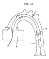
- FIG 13 is a longitudinal cross sectional view of a distal portion of the aorta and the closed chest IAB-based ventricular assist device with a diaphragm in a blood pump position.
-
- FIG 1 illustrates a longitudinal cross section of an inserted prior art cardiac assist pump, generally designated 10, comprising an
external pump 20 and acannula 30 having aproximal end 31, adistal end 32, anintake valve 40,outlet valves 50, and alumen 51. Preferably thecannula 30 is inserted percutaneously, through anincision 61 in theperipheral artery 60, or another suitable artery such as the femoral artery, and passed upstream throughaorta 70 andaortic valve 140 into theleft ventricle 80 ofheart 90. The method of insertion is substantially similar to methods for insertion of other types of cardiac cannulae known in the art. The length of thecannula 30 is approximately 60 cm, which is generally sufficient to ensure that when the distal end of thecannula 30 is positioned in theleft ventricle 80 the proximal end of thecannula 30 remains outside the body of the patient, adjacent to theincision 61. Alternatively, thecannula 30 may be inserted surgically through a suitable incision elsewhere in the arterial system. - Once the
cannula 30 is in place thepump 20 creates a pressure differential in thecannula 30, and as a result, theintake valve 40, located at thedistal end 32 of thecannula 30, is opened, and blood flows from theleft ventricle 80 intolumen 51.Outlet valves 50 are kept closed while the blood fills thelumen 51. After an outside chamber (not shown) fills up with blood, thepump 20 creates an opposite pressure differential in the chamber, and as a result, theintake valve 40 is closed and theoutlet valves 50 are opened and the blood is forced out of thelumen 51 and into theaorta 70. - FIG 2 illustrates a longitudinal cross section of the present invention, generally designated 11, inserted into the
aorta 70 of a patient. Thepresent invention 11 comprises an Intra-Aortic Balloon (IAB)catheter 100 and apumping chamber 110 havingoutlet valves 115. Thepumping chamber 110 comprises a largertube chamber portion 111, having aproximal end 99, and a smallertube cannula portion 112, having adistal end 113. Note that the directional term "distal" refers to a location closer to the heart. Aleaflet intake valve 114, or other suitable intake valve, is attached to thedistal end 113 of the smallertube cannula portion 112 of thepumping chamber 110. TheIAB catheter 100 comprises generally aballoon membrane 101, anouter tube 102, atip 103, and anexternal pump 20. TheIAB catheter 100 is generally inserted percutaneously into theaorta 70 through anoptional insertion sheath 71, and thetip 103 is placed just distal to the leftsubclavian artery 72. identical to prior art IABs theexternal pump 20 shuttles a non-blood material, such as gas, back and forth in theouter tube 102 causing theballon membrane 101 to inflate and deflate rapidly. Theballoon membrane 101 is slidingly disposed within the largertube chamber portion 111 of thepumping chamber 110. Theproximal end 99 of the largertube chamber portion 111 is slidingly attached to theouter tube 102 of theIAB catheter 100 such that blood cannot escape through saidproximal end 99. - FIGS 3 and 4 illustrate a longitudinal cross section of the
pumping chamber 110 and a distal portion of theIAB catheter 100 inserted into theaorta 70 of a patient. FIG 3 illustrates the means by which blood is forced into the smallertube cannula portion 112. Theballoon membrane 101 is in a deflated state, and as a result, the pressure in thepumping chamber 110 is lower than the pressure in theaorta 70, and preferably, is close to that in theleft ventricle 80. The pressure differential causes theleaflet intake valve 114 to open and allow blood to flow into thedistal end 113 of the smallertube cannula portion 112. Lower pressure in thepumping chamber 110 also causes theoutlet valves 115 to close, thereby, preventing any blood from escaping through saidoutlet valves 115 into theaorta 70. Note that as illustrated in FIG 3 theaortic valve 140 opens in concert with theoutlet valves 115. This representation assumes that theheart 90 is pumping synchronously with the closed chest in-based ventricular assistdevice 11. However, use of thepresent invention 11 is anticipated with a totally failed left heart. In such a case, the diameter of the smallertube cannula portion 112 may be made larger so as to accommodate the entire blood flow. Note further that the smallertube cannula portion 112 and the annular area between theballoon membrane 101 and the largertube chamber portion 111 are the only blood containing portions of thepresent invention 11. TheIAB catheter 100 may be considered the non-blood containing portion of thepresent invention 11. FIG 4 illustrates the means by which the blood is forced out of thepumping chamber 110. Theballoon membrane 101 is inflated causing the pressure in thepumping chamber 110 to increase. As a result, theintake valve 114 is forced shut by blood attempting to reenter theleft ventricle 80, and theoutlet valves 115 are forced open allowing blood in both the smallertube cannula portion 112 and the largertube chamber portion 111 to flow into theaorta 70. Note thatoutlet valves 115 may be located throughout thepumping chamber 110. Note that the present invention li, with minor variations, is anticipated for use as a right ventricular assist device as well. - FIG 5 illustrates an alternate embodiment of the
intake valve 114. Theintake valve 114 comprises adisk 116 that is rotatably attached to the smallertube cannula portion 112 by means of apin 117. As blood attempts to flow into theleft ventricle 80 thedisk 116 rotates to its transverse closed position and stays there as a result ofstoppers 118, preventing blood from reentering theleft ventricle 80. As blood attempts to flow out from theleft ventricle 80, as illustrated by FIG 6, thedisk 116 spins back to its longitudinal open position and allows the blood to flow into thepumping chamber 110. Note that different forms of intake and outlet valves are anticipated. - Preferably the
IAB catheter 100 and thepumping chamber 110 are inserted percutaneously in series or as one unit. The method for inserting an IAB catheter is well known in the art. The preferred embodiment of thepumping chamber 110, capable of being inserted percutaneously, is illustrated in FIGS 7-8. Thepumping chamber 110 must be able to withstand the high pressures generated in theaorta 70, as a result of the deflation of theballoon membrane 101, during actual blood pumping, and yet it must also be flexible enough during insertion to be capable of being advanced into theaorta 70. FIG 7 illustrates a longitudinal cross section of the fluid-filledpumping chamber 110, disposed about theballoon membrane 101 of theIAB catheter 100, which demonstrates these properties. TheIAB catheter 100 is percutaneously inserted such that thetip 103 is just proximal the leftsubclavian artery 72. Thepumping chamber 110 has apump tube 118, having adistal end 113 and aproximal end 99, and afluid delivery tube 119 attached to thepump tube 118. Thepumping chamber 110 is disposed about aproximal end 126 of theIAB catheter 100 and advanced into theaorta 70 such thatdistal end 113 of thepump tube 118 enters theleft ventricle 80. Theproximal end 99 of thepump tube 118 is slidingly attached to theouter tube 102 of theIAB catheter 100 such that blood cannot escape through saidproximal end 99. Alumen 120 extends the entire length of thefluid delivery tube 119 and runs in a helical or other similar manner around thepump tube 118. Once positioned in theaorta 70 thelumen 120 is filled with fluid. The fluid-filledlumen 120 increases the rigidity of thepumping chamber 110 such that it is capable of withstanding pressures generated in theaorta 70 during deflation of theballoon membrane 101. Upon completion of therapy, the fluid is pumped out of thelumen 120 and thepumping chamber 110 is once again supple and small enough to be removed from theaorta 70 percutaneously. FIG 8 illustrates a perspective view of the fluid-filledpumping chamber 110 illustrated in FIG 7. As an alternative to the fluid-filledhelical lumen 120, fluid-filled pockets or fluid-filled surface sectors, of various geometries, may be used. - FIG 9 illustrates an
alternate pumping chamber 110 made from intercoiled wires covered with an elastic leak proof or other suitable material, similar to expandable stents on the market, and has the property that when pulled or stretched its cross sectional diameter decreases. Insertion of the closed chest IAB-based ventricular assistdevice 11 incorporating thepumping chamber 110, as illustrated in FIG 9, comprises the following steps. TheIAB catheter 100 is first inserted into theaorta 70. Next, thepumping chamber 110, in a stretched state, is advanced over theIAB catheter 100 into theaorta 70. Upon positioning of thepumping chamber 110, such that the balloon,membrane 101 of theIAB catheter 100 is disposed within thepumping chamber 100, thepumping chamber 110 is released and allowed to expand from its smaller diameter stretched state to its larger diameter unstretched state. FIG 9 illustrates a plain view of thepumping chamber 110 in its unstretched state. FIG 10 illustrates a plain view of thepumping chamber 110 in its stretched state. Thepumping chamber 110 is attached to theIAB catheter 100 in the same manner as thepumping chamber 110 illustrated in FIG 2. Upon completion of therapy, thepumping chamber 110 is stretched to its smaller diameter stretched state and is then removed percutaneously. After removal of thepumping chamber 110 theIAB catheter 100 is removed percutaneously. Thepumping chamber 110 is inserted into and removed from the patient in a manner similar to other expandable stents on the market, such as the Corvita stent (produced by Corvita Corp, Miami, FL). As an alternative method of insertion, theIAB catheter 100 may be inserted after insertion of thepumping chamber 110. - FIG 11 illustrates a longitudinal cross section of an alternate embodiment of the
present invention 11 inserted into theaorta 70 comprising acannula 160 having agas tube portion 128, aproximal end 126, and apumping chamber 110 having adistal end 113 and adiaphragm 127. Theproximal end 126 of thegas tube portion 128 is connected to an externalnon-blood pump 20. The distal end of thepumping chamber 110 is inserted into theleft ventricle 80 of the heart 90-Similar to the first embodiment of thepresent invention 11, blood flow is limited only to thepumping chamber 110. Thepumping chamber 110 is the only blood containing portion of thepresent invention 11. Thegas tube portion 128 is filled with a non-blood material, such as helium. Thegas tube portion 128 basically replaces theIAB catheter 100, as illustrated in FIG 2, as the non-blood containing portion of thepresent invention 11. The diameter of thegas tube portion 128 may be made smaller than the diameter of thepumping chamber 110. Reduction of the diameter of thegas tube portion 128 allows for more blood flow around thegas tube portion 128 and thus improves circulation in the patient during the procedure. - As illustrated in FIG 12, as soon as the pump 20 (FIG 11) decreases the pressure in the
gas tube portion 128 thediaphragm 127 moves to a blood intake position, and as a result, theoutlet valves 115 close, theintake valve 114 opens, and blood rushes into thepumping chamber 110. FIG 12 illustrates a longitudinal cross section of a distal portion of the alternate embodiment illustrated in FIG 11 with thediaphragm 127 in a blood intake state. As illustrated in FIG 13, as soon as thepump 20 increases the pressure in thegas tube portion 128 the diaphragm moves to a blood pump position, and as a result, theintake valve 114 closes, theoutlet valves 115 open, and blood rushes out of thepumping chamber 110 into theaorta 70.
Claims (8)
- A device for pumping blood comprising an intra-aortic balloon catheter (100) having a balloon membrane (101) and a pumping chamber (110) having a distal end, a larger tube chamber portion (111), and a communicating smaller tube cannula portion (112), the larger tube chamber portion (111) has a proximal end, an opening on its proximal end, and a larger outer diameter than the smaller tube cannula portion (112), the device for pumping blood characterized in that the balloon membrane (101) in a deflated state fits within and is passable through the opening on the proximal end of the larger tube chamber portion (111), the balloon membrane (101) is disposed within the larger tube chamber portion (111), the pumping chamber (110) being adapted for insertion into the aorta of a patient and having at least one intake valve (114) adjacent to its distal end and at least one outlet valve (115) closer to the balloon membrane (101) than the intake valve (114), when the balloon membrane (101) is deflated blood enters the pumping chamber (110) via the intake valve (114) and the outlet valves (115) are in a closed state, when the balloon membrane (101) is inflated the intake valve (114) closes and blood inside the pumping chamber (110) is forced out through the outlet valves (115), upon insertion of the pumping chamber (110) within a patient the distal end of the smaller tube cannula portion (112) is in the ventricle of the patient.
- The device for pumping blood as claimed in claim 1 wherein the pumping chamber (110) is collapsible.
- The device for pumping blood as claimed in claim 1 wherein the pumping chamber (110) has the property that when stretched its cross sectional diameter decreases and that when relieved from stretch returns to its previous larger cross sectional diameter.
- The device for pumping blood as claimed in claim 3 wherein the pumping chamber (110) is made from intercoiled wires.
- The device for pumping blood as claimed in claim 1 wherein the pumping chamber (110) comprises a stiffening means which holds a stiffening material.
- The device for pumping blood as claimed in claim 5 wherein the stiffening material is a fluid.
- The device for pumping blood as claimed in claim 5 wherein the stiffening means comprises a lumen capable of receiving the stiffening material and a supply tube for supplying the stiffening material.
- The device for pumping blood as claimed in claim 7 wherein the lumen runs in a helical manner around the pumping chamber (110).
Applications Claiming Priority (3)
| Application Number | Priority Date | Filing Date | Title |
|---|---|---|---|
| US09/052,491 US5928132A (en) | 1998-03-31 | 1998-03-31 | Closed chest intra-aortic balloon based ventricular assist device |
| US52491 | 1998-03-31 | ||
| PCT/US1999/005172 WO1999049911A1 (en) | 1998-03-31 | 1999-03-10 | Closed chest intra-aortic balloon based ventricular assist device |
Publications (2)
| Publication Number | Publication Date |
|---|---|
| EP1066066A1 EP1066066A1 (en) | 2001-01-10 |
| EP1066066B1 true EP1066066B1 (en) | 2004-07-21 |
Family
ID=21977949
Family Applications (1)
| Application Number | Title | Priority Date | Filing Date |
|---|---|---|---|
| EP19990912354 Expired - Lifetime EP1066066B1 (en) | 1998-03-31 | 1999-03-10 | Closed chest intra-aortic balloon based ventricular assist device |
Country Status (8)
| Country | Link |
|---|---|
| US (1) | US5928132A (en) |
| EP (1) | EP1066066B1 (en) |
| JP (1) | JP4022372B2 (en) |
| AT (1) | ATE271398T1 (en) |
| AU (1) | AU3074599A (en) |
| DE (1) | DE69918816T2 (en) |
| ES (1) | ES2224619T3 (en) |
| WO (1) | WO1999049911A1 (en) |
Cited By (2)
| Publication number | Priority date | Publication date | Assignee | Title |
|---|---|---|---|---|
| CN107050544A (en) * | 2011-12-22 | 2017-08-18 | Ecp发展有限责任公司 | Fluid pump with the pump case that pump rotor can be accommodated inside it |
| US10888644B2 (en) | 2019-02-06 | 2021-01-12 | inQB8 Medical Technologies, LLC | Intra-cardiac left atrial and dual support systems |
Families Citing this family (56)
| Publication number | Priority date | Publication date | Assignee | Title |
|---|---|---|---|---|
| US7780628B1 (en) * | 1999-01-11 | 2010-08-24 | Angiodynamics, Inc. | Apparatus and methods for treating congestive heart disease |
| US6749598B1 (en) * | 1999-01-11 | 2004-06-15 | Flowmedica, Inc. | Apparatus and methods for treating congestive heart disease |
| US7329236B2 (en) * | 1999-01-11 | 2008-02-12 | Flowmedica, Inc. | Intra-aortic renal drug delivery catheter |
| US7481803B2 (en) * | 2000-11-28 | 2009-01-27 | Flowmedica, Inc. | Intra-aortic renal drug delivery catheter |
| US7022100B1 (en) | 1999-09-03 | 2006-04-04 | A-Med Systems, Inc. | Guidable intravascular blood pump and related methods |
| US7150737B2 (en) * | 2001-07-13 | 2006-12-19 | Sci/Med Life Systems, Inc. | Methods and apparatuses for navigating the subarachnoid space |
| US6669624B2 (en) | 2002-03-26 | 2003-12-30 | O. Howard Frazier | Temporary heart-assist system |
| US7063679B2 (en) * | 2002-09-20 | 2006-06-20 | Flowmedica, Inc. | Intra-aortic renal delivery catheter |
| US20050197624A1 (en) | 2004-03-04 | 2005-09-08 | Flowmedica, Inc. | Sheath for use in peripheral interventions |
| EP1624909A2 (en) * | 2002-09-20 | 2006-02-15 | FlowMedica, Inc. | Appartus and method for inserting an intra-aorta catheter trough a delivery sheath |
| JP2006508776A (en) | 2002-09-20 | 2006-03-16 | フローメディカ,インコーポレイテッド | Method and apparatus for selective substance delivery via an intrarenal catheter |
| US7993325B2 (en) | 2002-09-20 | 2011-08-09 | Angio Dynamics, Inc. | Renal infusion systems and methods |
| AU2003294226A1 (en) * | 2002-09-20 | 2004-04-23 | Flowmedica, Inc. | Method and apparatus for intra aortic substance delivery to a branch vessel |
| US7468050B1 (en) | 2002-12-27 | 2008-12-23 | L. Vad Technology, Inc. | Long term ambulatory intra-aortic balloon pump |
| US8540618B2 (en) | 2003-01-31 | 2013-09-24 | L-Vad Technology, Inc. | Stable aortic blood pump implant |
| US8721515B2 (en) * | 2003-01-31 | 2014-05-13 | L-Vad Technology, Inc. | Rigid body aortic blood pump implant |
| EP1635736A2 (en) | 2003-06-05 | 2006-03-22 | FlowMedica, Inc. | Systems and methods for performing bi-lateral interventions or diagnosis in branched body lumens |
| US7374531B1 (en) | 2003-06-11 | 2008-05-20 | L. Vad Technology, Inc. | Long term ambulatory intra-aortic balloon pump with three dimensional tortuous shape |
| DE10336902C5 (en) | 2003-08-08 | 2019-04-25 | Abiomed Europe Gmbh | Intracardiac pumping device |
| US7066874B2 (en) * | 2004-01-06 | 2006-06-27 | Bay Innovation Group, Llc | Devices and methods for blood flow assistance |
| US7811221B2 (en) * | 2004-02-10 | 2010-10-12 | Yossi Gross | Extracardiac blood flow amplification device |
| US7172551B2 (en) * | 2004-04-12 | 2007-02-06 | Scimed Life Systems, Inc. | Cyclical pressure coronary assist pump |
| US20060069323A1 (en) * | 2004-09-24 | 2006-03-30 | Flowmedica, Inc. | Systems and methods for bi-lateral guidewire cannulation of branched body lumens |
| US7544160B2 (en) * | 2005-02-10 | 2009-06-09 | Yossi Gross | Extracardiac blood flow amplification device |
| US7479102B2 (en) * | 2005-02-28 | 2009-01-20 | Robert Jarvik | Minimally invasive transvalvular ventricular assist device |
| WO2007089500A2 (en) * | 2006-01-30 | 2007-08-09 | Pong-Jeu Lu | Dual-pulsation bi-ventricular assist device |
| WO2007132449A2 (en) * | 2006-05-11 | 2007-11-22 | Yossi Gross | Implantable respiration therapy device |
| US7771401B2 (en) | 2006-06-08 | 2010-08-10 | Angiodynamics, Inc. | Selective renal cannulation and infusion systems and methods |
| US7914436B1 (en) | 2006-06-12 | 2011-03-29 | Abiomed, Inc. | Method and apparatus for pumping blood |
| DE102007012817A1 (en) * | 2007-03-16 | 2008-09-18 | Mwf Consult Ltd. | Device for supporting the heart and the circulation |
| US8439859B2 (en) | 2007-10-08 | 2013-05-14 | Ais Gmbh Aachen Innovative Solutions | Catheter device |
| US20090259089A1 (en) * | 2008-04-10 | 2009-10-15 | Daniel Gelbart | Expandable catheter for delivery of fluids |
| US20090270815A1 (en) * | 2008-04-29 | 2009-10-29 | Infraredx, Inc. | Catheter Priming System |
| US8540616B2 (en) * | 2008-05-05 | 2013-09-24 | Coherex Medical, Inc. | Ventricular assist device and related methods |
| WO2009137530A2 (en) | 2008-05-05 | 2009-11-12 | Coherex Medical, Inc. | Ventricular assist device and related methods |
| WO2010028305A2 (en) * | 2008-09-05 | 2010-03-11 | Cardiopolymers, Inc. | Process for generating microwalled encapsulation balloons |
| US8523756B2 (en) * | 2008-12-31 | 2013-09-03 | National Cheng Kung University | Cardiac compression system |
| EP2298371A1 (en) | 2009-09-22 | 2011-03-23 | ECP Entwicklungsgesellschaft mbH | Function element, in particular fluid pump with a housing and a transport element |
| JP2014501554A (en) * | 2010-11-05 | 2014-01-23 | タフツ メディカル センター インコーポレイテッド | Cannula with bifurcated tip for cardiac assist device |
| DE102014003153B4 (en) * | 2014-03-03 | 2015-10-08 | Novapump Gmbh | Catheter for directionally directing a fluid, in particular a body fluid |
| US11583670B2 (en) | 2014-03-03 | 2023-02-21 | Novapump Gmbh | Catheter for the directional conveyance of a fluid, particularly a body fluid |
| WO2016041220A1 (en) | 2014-09-15 | 2016-03-24 | 靳立军 | Left ventricle assist device |
| CN104174078B (en) * | 2014-09-15 | 2016-09-21 | 靳立军 | A kind of left ventricular assist device |
| DE102015216050A1 (en) * | 2015-08-21 | 2017-02-23 | Robert Bosch Gmbh | Pump for a fluid and cardiac support system |
| EP3556409B1 (en) | 2016-10-25 | 2022-01-05 | Magenta Medical Ltd. | Ventricular assist device |
| EP4233989A3 (en) | 2017-06-07 | 2023-10-11 | Shifamed Holdings, LLC | Intravascular fluid movement devices, systems, and methods of use |
| US11351355B2 (en) * | 2017-10-19 | 2022-06-07 | Datascope Corporation | Devices for pumping blood, related systems, and related methods |
| EP3710076B1 (en) | 2017-11-13 | 2023-12-27 | Shifamed Holdings, LLC | Intravascular fluid movement devices, systems, and methods of use |
| EP3854444A1 (en) | 2018-01-10 | 2021-07-28 | Magenta Medical Ltd. | Distal tip element for blood pump |
| US10905808B2 (en) | 2018-01-10 | 2021-02-02 | Magenta Medical Ltd. | Drive cable for use with a blood pump |
| JP7410034B2 (en) | 2018-02-01 | 2024-01-09 | シファメド・ホールディングス・エルエルシー | Intravascular blood pump and methods of use and manufacture |
| EP3782665B1 (en) | 2019-01-24 | 2021-08-25 | Magenta Medical Ltd. | Ventricular assist device |
| US10987456B2 (en) * | 2019-09-23 | 2021-04-27 | Synecor Llc | Devices for use in extracting percutaneous ventricular assist devices |
| CN110575577B (en) * | 2019-09-25 | 2022-04-05 | 周诚 | Novel auxiliary device for treating Fontan circulatory failure |
| CN112870547A (en) * | 2021-02-07 | 2021-06-01 | 华中科技大学同济医学院附属协和医院 | Serial axial flow pump auxiliary device for treating Fontan postoperative circulation failure and using method thereof |
| CN113018543B (en) * | 2021-03-02 | 2021-10-08 | 江苏赛腾医疗科技有限公司 | Diversion control system |
Family Cites Families (12)
| Publication number | Priority date | Publication date | Assignee | Title |
|---|---|---|---|---|
| US4014317A (en) * | 1972-02-18 | 1977-03-29 | The United States Of America As Represented By The Department Of Health, Education And Welfare | Multipurpose cardiocirculatory assist cannula and methods of use thereof |
| US3974825A (en) * | 1975-10-01 | 1976-08-17 | Baylor College Of Medicine | Remote electrical monitoring of gas activated blood pumps |
| US4015590A (en) * | 1976-04-12 | 1977-04-05 | Baylor College Of Medicine | Balloon activated blood pump |
| GB1526099A (en) * | 1976-11-19 | 1978-09-27 | Bodnar E | Semi-biological internal circuit pumping device |
| US4861330A (en) * | 1987-03-12 | 1989-08-29 | Gene Voss | Cardiac assist device and method |
| US4906229A (en) * | 1988-05-03 | 1990-03-06 | Nimbus Medical, Inc. | High-frequency transvalvular axisymmetric blood pump |
| US5092844A (en) * | 1990-04-10 | 1992-03-03 | Mayo Foundation For Medical Education And Research | Intracatheter perfusion pump apparatus and method |
| ES2020787A6 (en) * | 1990-07-20 | 1991-09-16 | Figuera Aymerich Diego | Intra-ventricular expansible assist pump |
| US5332403A (en) * | 1992-08-17 | 1994-07-26 | Jack Kolff | LVAD with t-shape and unidirectional valve |
| FR2733143B1 (en) * | 1995-04-21 | 1997-11-07 | Nycomed Lab Sa | DEVICE FOR TEMPORARILY SHUTTERING A BODY CHANNEL, ESPECIALLY USEFUL FOR PRESSURE HEART ASSISTANCE |
| IL114517A0 (en) * | 1995-07-10 | 1995-11-27 | R D C Rafael Dev Corp Ltd | Heart assist system |
| US5820542A (en) * | 1996-10-31 | 1998-10-13 | Momentum Medical, Inc. | Modified circulatory assist device |
-
1998
- 1998-03-31 US US09/052,491 patent/US5928132A/en not_active Expired - Lifetime
-
1999
- 1999-03-10 ES ES99912354T patent/ES2224619T3/en not_active Expired - Lifetime
- 1999-03-10 JP JP2000540873A patent/JP4022372B2/en not_active Expired - Fee Related
- 1999-03-10 AU AU30745/99A patent/AU3074599A/en not_active Abandoned
- 1999-03-10 WO PCT/US1999/005172 patent/WO1999049911A1/en active IP Right Grant
- 1999-03-10 EP EP19990912354 patent/EP1066066B1/en not_active Expired - Lifetime
- 1999-03-10 DE DE69918816T patent/DE69918816T2/en not_active Expired - Lifetime
- 1999-03-10 AT AT99912354T patent/ATE271398T1/en not_active IP Right Cessation
Cited By (3)
| Publication number | Priority date | Publication date | Assignee | Title |
|---|---|---|---|---|
| CN107050544A (en) * | 2011-12-22 | 2017-08-18 | Ecp发展有限责任公司 | Fluid pump with the pump case that pump rotor can be accommodated inside it |
| US10888644B2 (en) | 2019-02-06 | 2021-01-12 | inQB8 Medical Technologies, LLC | Intra-cardiac left atrial and dual support systems |
| US11883640B2 (en) | 2019-02-06 | 2024-01-30 | inQB8 Medical Technologies, LLC | Intra-cardiac left atrial and dual support systems |
Also Published As
| Publication number | Publication date |
|---|---|
| DE69918816D1 (en) | 2004-08-26 |
| EP1066066A1 (en) | 2001-01-10 |
| US5928132A (en) | 1999-07-27 |
| ATE271398T1 (en) | 2004-08-15 |
| WO1999049911A1 (en) | 1999-10-07 |
| ES2224619T3 (en) | 2005-03-01 |
| JP4022372B2 (en) | 2007-12-19 |
| JP2002509769A (en) | 2002-04-02 |
| AU3074599A (en) | 1999-10-18 |
| DE69918816T2 (en) | 2005-08-18 |
Similar Documents
| Publication | Publication Date | Title |
|---|---|---|
| EP1066066B1 (en) | Closed chest intra-aortic balloon based ventricular assist device | |
| US4592340A (en) | Artificial catheter means | |
| JP3265650B2 (en) | Blood circulation assist device | |
| US6299575B1 (en) | Implantable heart assist system | |
| US6136025A (en) | Endoscopic arterial pumps for treatment of cardiac insufficiency and venous pumps for right-sided cardiac support | |
| US4195623A (en) | Parallel aorta balloon pump and method of using same | |
| US8480555B2 (en) | Method and apparatus for pumping blood | |
| US4902272A (en) | Intra-arterial cardiac support system | |
| US6666814B2 (en) | Enhanced intra-aortic balloon assist device | |
| ES2407680T3 (en) | Cardiac assist devices, systems and methods | |
| EP2209508B1 (en) | Pulsatile blood pump | |
| US4240409A (en) | Apparatus for assisting circulation of blood | |
| US20040064091A1 (en) | Apparatus and methods for treating congestive heart disease | |
| US20020169413A1 (en) | Apparatus and methods for treating congestive heart disease | |
| EP1035880A1 (en) | Heart assist system with cannula pump | |
| WO1998028034A1 (en) | Valve for a heart assist device | |
| US6228018B1 (en) | Removable left ventricular assist device with an aortic support apparatus | |
| CN116099120A (en) | Combined auxiliary treatment system for heart and kidney |
Legal Events
| Date | Code | Title | Description |
|---|---|---|---|
| PUAI | Public reference made under article 153(3) epc to a published international application that has entered the european phase |
Free format text: ORIGINAL CODE: 0009012 |
|
| 17P | Request for examination filed |
Effective date: 20000929 |
|
| AK | Designated contracting states |
Kind code of ref document: A1 Designated state(s): AT BE CH CY DE DK ES FI FR GB GR IE IT LI LU MC NL PT SE |
|
| GRAP | Despatch of communication of intention to grant a patent |
Free format text: ORIGINAL CODE: EPIDOSNIGR1 |
|
| GRAS | Grant fee paid |
Free format text: ORIGINAL CODE: EPIDOSNIGR3 |
|
| GRAA | (expected) grant |
Free format text: ORIGINAL CODE: 0009210 |
|
| AK | Designated contracting states |
Kind code of ref document: B1 Designated state(s): AT BE CH CY DE DK ES FI FR GB GR IE IT LI LU MC NL PT SE |
|
| PG25 | Lapsed in a contracting state [announced via postgrant information from national office to epo] |
Ref country code: NL Free format text: LAPSE BECAUSE OF FAILURE TO SUBMIT A TRANSLATION OF THE DESCRIPTION OR TO PAY THE FEE WITHIN THE PRESCRIBED TIME-LIMIT Effective date: 20040721 Ref country code: LI Free format text: LAPSE BECAUSE OF FAILURE TO SUBMIT A TRANSLATION OF THE DESCRIPTION OR TO PAY THE FEE WITHIN THE PRESCRIBED TIME-LIMIT Effective date: 20040721 Ref country code: FI Free format text: LAPSE BECAUSE OF FAILURE TO SUBMIT A TRANSLATION OF THE DESCRIPTION OR TO PAY THE FEE WITHIN THE PRESCRIBED TIME-LIMIT Effective date: 20040721 Ref country code: CH Free format text: LAPSE BECAUSE OF FAILURE TO SUBMIT A TRANSLATION OF THE DESCRIPTION OR TO PAY THE FEE WITHIN THE PRESCRIBED TIME-LIMIT Effective date: 20040721 Ref country code: BE Free format text: LAPSE BECAUSE OF FAILURE TO SUBMIT A TRANSLATION OF THE DESCRIPTION OR TO PAY THE FEE WITHIN THE PRESCRIBED TIME-LIMIT Effective date: 20040721 Ref country code: AT Free format text: LAPSE BECAUSE OF FAILURE TO SUBMIT A TRANSLATION OF THE DESCRIPTION OR TO PAY THE FEE WITHIN THE PRESCRIBED TIME-LIMIT Effective date: 20040721 |
|
| REG | Reference to a national code |
Ref country code: GB Ref legal event code: FG4D |
|
| REG | Reference to a national code |
Ref country code: CH Ref legal event code: EP |
|
| REG | Reference to a national code |
Ref country code: IE Ref legal event code: FG4D |
|
| REF | Corresponds to: |
Ref document number: 69918816 Country of ref document: DE Date of ref document: 20040826 Kind code of ref document: P |
|
| PG25 | Lapsed in a contracting state [announced via postgrant information from national office to epo] |
Ref country code: SE Free format text: LAPSE BECAUSE OF FAILURE TO SUBMIT A TRANSLATION OF THE DESCRIPTION OR TO PAY THE FEE WITHIN THE PRESCRIBED TIME-LIMIT Effective date: 20041021 Ref country code: GR Free format text: LAPSE BECAUSE OF FAILURE TO SUBMIT A TRANSLATION OF THE DESCRIPTION OR TO PAY THE FEE WITHIN THE PRESCRIBED TIME-LIMIT Effective date: 20041021 Ref country code: DK Free format text: LAPSE BECAUSE OF FAILURE TO SUBMIT A TRANSLATION OF THE DESCRIPTION OR TO PAY THE FEE WITHIN THE PRESCRIBED TIME-LIMIT Effective date: 20041021 |
|
| NLV1 | Nl: lapsed or annulled due to failure to fulfill the requirements of art. 29p and 29m of the patents act | ||
| REG | Reference to a national code |
Ref country code: CH Ref legal event code: PL |
|
| REG | Reference to a national code |
Ref country code: ES Ref legal event code: FG2A Ref document number: 2224619 Country of ref document: ES Kind code of ref document: T3 |
|
| PG25 | Lapsed in a contracting state [announced via postgrant information from national office to epo] |
Ref country code: LU Free format text: LAPSE BECAUSE OF NON-PAYMENT OF DUE FEES Effective date: 20050310 Ref country code: IE Free format text: LAPSE BECAUSE OF NON-PAYMENT OF DUE FEES Effective date: 20050310 Ref country code: CY Free format text: LAPSE BECAUSE OF FAILURE TO SUBMIT A TRANSLATION OF THE DESCRIPTION OR TO PAY THE FEE WITHIN THE PRESCRIBED TIME-LIMIT Effective date: 20050310 |
|
| PG25 | Lapsed in a contracting state [announced via postgrant information from national office to epo] |
Ref country code: MC Free format text: LAPSE BECAUSE OF NON-PAYMENT OF DUE FEES Effective date: 20050331 |
|
| PLBE | No opposition filed within time limit |
Free format text: ORIGINAL CODE: 0009261 |
|
| STAA | Information on the status of an ep patent application or granted ep patent |
Free format text: STATUS: NO OPPOSITION FILED WITHIN TIME LIMIT |
|
| ET | Fr: translation filed | ||
| 26N | No opposition filed |
Effective date: 20050422 |
|
| REG | Reference to a national code |
Ref country code: IE Ref legal event code: MM4A |
|
| PG25 | Lapsed in a contracting state [announced via postgrant information from national office to epo] |
Ref country code: PT Free format text: LAPSE BECAUSE OF NON-PAYMENT OF DUE FEES Effective date: 20041221 |
|
| PGFP | Annual fee paid to national office [announced via postgrant information from national office to epo] |
Ref country code: GB Payment date: 20100331 Year of fee payment: 12 |
|
| PGFP | Annual fee paid to national office [announced via postgrant information from national office to epo] |
Ref country code: FR Payment date: 20100419 Year of fee payment: 12 Ref country code: ES Payment date: 20100420 Year of fee payment: 12 |
|
| PGFP | Annual fee paid to national office [announced via postgrant information from national office to epo] |
Ref country code: IT Payment date: 20100422 Year of fee payment: 12 |
|
| REG | Reference to a national code |
Ref country code: DE Ref legal event code: R409 Ref document number: 69918816 Country of ref document: DE |
|
| GBPC | Gb: european patent ceased through non-payment of renewal fee |
Effective date: 20110310 |
|
| REG | Reference to a national code |
Ref country code: DE Ref legal event code: R409 Ref document number: 69918816 Country of ref document: DE |
|
| REG | Reference to a national code |
Ref country code: FR Ref legal event code: ST Effective date: 20111130 |
|
| PG25 | Lapsed in a contracting state [announced via postgrant information from national office to epo] |
Ref country code: FR Free format text: LAPSE BECAUSE OF NON-PAYMENT OF DUE FEES Effective date: 20110331 |
|
| PG25 | Lapsed in a contracting state [announced via postgrant information from national office to epo] |
Ref country code: GB Free format text: LAPSE BECAUSE OF NON-PAYMENT OF DUE FEES Effective date: 20110310 Ref country code: IT Free format text: LAPSE BECAUSE OF NON-PAYMENT OF DUE FEES Effective date: 20110310 |
|
| REG | Reference to a national code |
Ref country code: ES Ref legal event code: FD2A Effective date: 20120509 |
|
| PGFP | Annual fee paid to national office [announced via postgrant information from national office to epo] |
Ref country code: DE Payment date: 20110531 Year of fee payment: 13 |
|
| PG25 | Lapsed in a contracting state [announced via postgrant information from national office to epo] |
Ref country code: ES Free format text: LAPSE BECAUSE OF NON-PAYMENT OF DUE FEES Effective date: 20110311 |
|
| REG | Reference to a national code |
Ref country code: DE Ref legal event code: R119 Ref document number: 69918816 Country of ref document: DE Effective date: 20121002 Ref country code: DE Ref legal event code: R119 Ref document number: 69918816 Country of ref document: DE Effective date: 20111001 |
|
| PG25 | Lapsed in a contracting state [announced via postgrant information from national office to epo] |
Ref country code: DE Free format text: LAPSE BECAUSE OF NON-PAYMENT OF DUE FEES Effective date: 20121002 |