EP1065909A2 - Système de microphones suppresseur de bruit - Google Patents
Système de microphones suppresseur de bruit Download PDFInfo
- Publication number
- EP1065909A2 EP1065909A2 EP20000305471 EP00305471A EP1065909A2 EP 1065909 A2 EP1065909 A2 EP 1065909A2 EP 20000305471 EP20000305471 EP 20000305471 EP 00305471 A EP00305471 A EP 00305471A EP 1065909 A2 EP1065909 A2 EP 1065909A2
- Authority
- EP
- European Patent Office
- Prior art keywords
- signals
- sound
- gain function
- sensors
- responsive
- Prior art date
- Legal status (The legal status is an assumption and is not a legal conclusion. Google has not performed a legal analysis and makes no representation as to the accuracy of the status listed.)
- Withdrawn
Links
Images


Classifications
-
- H—ELECTRICITY
- H04—ELECTRIC COMMUNICATION TECHNIQUE
- H04R—LOUDSPEAKERS, MICROPHONES, GRAMOPHONE PICK-UPS OR LIKE ACOUSTIC ELECTROMECHANICAL TRANSDUCERS; DEAF-AID SETS; PUBLIC ADDRESS SYSTEMS
- H04R3/00—Circuits for transducers, loudspeakers or microphones
- H04R3/005—Circuits for transducers, loudspeakers or microphones for combining the signals of two or more microphones
-
- H—ELECTRICITY
- H04—ELECTRIC COMMUNICATION TECHNIQUE
- H04R—LOUDSPEAKERS, MICROPHONES, GRAMOPHONE PICK-UPS OR LIKE ACOUSTIC ELECTROMECHANICAL TRANSDUCERS; DEAF-AID SETS; PUBLIC ADDRESS SYSTEMS
- H04R2201/00—Details of transducers, loudspeakers or microphones covered by H04R1/00 but not provided for in any of its subgroups
- H04R2201/40—Details of arrangements for obtaining desired directional characteristic by combining a number of identical transducers covered by H04R1/40 but not provided for in any of its subgroups
- H04R2201/403—Linear arrays of transducers
-
- H—ELECTRICITY
- H04—ELECTRIC COMMUNICATION TECHNIQUE
- H04R—LOUDSPEAKERS, MICROPHONES, GRAMOPHONE PICK-UPS OR LIKE ACOUSTIC ELECTROMECHANICAL TRANSDUCERS; DEAF-AID SETS; PUBLIC ADDRESS SYSTEMS
- H04R2410/00—Microphones
- H04R2410/01—Noise reduction using microphones having different directional characteristics
Definitions
- This invention relates generally to the field of microphones, and specifically to noise cancellation and signal enhancement for microphones.
- Noise, echoes, and other interference may significantly degrade the perceptual quality of signals recorded by conventional microphones. Furthermore, if a noise-contaminated signal is passed to a voice encoder for compression, the quality of the decompressed signal may suffer further due to the encoder's inability to separate the noise from the signal. Acoustical echoes picked up by a microphone, arising for example, in speakerphones, hands-free communications, or teleconferencing, may be very annoying on the far side of the connection. When an echo is present, the only solution for truly full-duplex communications is to use acoustical echo canceling.
- U.S. Patent 5,305,307 to Chu, and U.S. Patent 5,566,167 to Duttweiler which are incorporated herein by reference, describe methods of acoustical echo cancellation.
- the first approach utilizes differences in statistical properties between a signal and noise.
- the noise is assumed to have stable, "near-stationary" characteristics compared to the signal.
- the term near-stationary means that the noise spectrum changes relatively slowly with respect to the spectrum of the signal. It is then possible to estimate the power levels of the noise in different frequency bands. Simultaneously, the short-term power levels of the signal in the same frequency bands are monitored. One or more frequency bands in the output signal are then suppressed or enhanced depending on the current signal-to-noise ratio.
- Fig. 1 illustrates a second approach to improving signal-to-noise ratio, using a noise-canceling microphone.
- the figure shows an acoustic noise-canceling microphone 20 and an electronic noise-canceling microphone 30.
- Noise canceling microphones have two openings, one close to the sound source (the front) and one farther from the source (the rear).
- Noise-canceling microphones utilize a net pressure difference caused by the separation of the openings.
- a single diaphragm 22 is displaced by the net pressure difference, and such displacement is reflected in the output signal.
- an electronic noise-canceling microphone two bundled microphones 32 and 34 are used, and the difference is computed electronically.
- Noise-canceling microphones operate on the assumption that the noise affects both openings substantially identically, so that the net pressure difference generated by the noise is effectively zero. Conversely, the signal generates a non-zero net pressure difference.
- the net pressure difference is affected by both the phase difference and the sound pressure (the amplitude) difference along the wave.
- the sound pressure is inversely proportional to the distance to the sound source.
- the sensitivity of the microphone is thus a function of the separation of the openings, and to increase the sensitivity, the separation needs to be relatively large. On the other hand, the larger the separation, the larger the differences in phase shift over the microphone operating frequency range.
- the separation between the openings is typically restricted to be less than 15 mm.
- Such a small separation only provides enough sound pressure difference when the sound source is very close to the microphone, i.e., when the microphone-source distance is less than about 3 cm.
- using noise-canceling microphones is mainly restricted to headsets or other devices mounted or held very close to a speaker's mouth.
- a third approach to coping with noise and interfering signals consists of using superdirectional microphones. Such microphones attempt to receive and amplify sounds coming from a relatively narrow range of angles about a directional axis intercepting the sound source of interest. Superdirectional microphones may also be built either acoustically or electronically. In the latter case, they are generally called "microphone arrays.”
- Fig. 2 is a schematic diagram of a microphone array system 36 comprising a microphone array 38 and a processor 42.
- Array 38 consists of two or more individual sound pressure sensors 40 distributed along an axis. Each individual sensor may be either omnidirectional, i.e., having a gain substantially fixed regardless of the direction of the incoming signal, or unidirectional, wherein the gain is a function of the direction of the incoming signal.
- Processor 42 combines input signals from each individual sensor so as to generate an output signal that discriminates between the sounds in the direction of interest and sounds from other directions. To achieve the discrimination, the processor computes the output signal as a linear combination of the input signals. In some cases, the input signals are filtered so that processor 42 may better exploit phase differences between individual sensors 40. Such phase differences are caused by the spatial separation of the individual sensors and by the angular separation between the sound source of interest and interfering sounds.
- a microphone array system may be either fixed or adaptive, depending on the type of processing provided.
- individual filters associated with the microphones are fixed, and do not depend on the signals acquired by individual sensors.
- the filters are chosen so that the array receives signals from a direction of interest, and attenuates all signals arriving from directions other than the direction of interest.
- the filters are automatically adapted during array operation, so as to better deal with varying specific situations.
- using superdirectional microphones has two major limitations. First, the use is limited to situations where there is a relatively large distance between the microphone array and the sound source. Second, the microphone array is not able to discriminate between the sound source of interest and a source that is closer or farther away but which lies in the same direction. For example, using superdirectional microphones in small or reverberant rooms does not generally provide a significant improvement in signal-to-noise ratio because of multiple wall reflections and because of the diffused character of the sounds in these rooms.
- the prior art approach to noise cancellation does not provide a microphone system or apparatus having noise-canceling characteristics for sources in the middle range of microphone-source distances (distances of the order of 3-100cm), or which are capable of dealing with all types of acoustic interference.
- microphone array apparatus comprises a set of two or more sound pressure sensors separated in space and a signal processor, which may be either analog or digital.
- the processor comprises a master signal generator, a set of frequency band splitters, a gain controller and a signal combiner.
- the master signal generator combines input signals from one or more of the pressure sensors to produce a master signal, having a fixed or adaptive beam pattern, by methods known in the art. Signals from each of the sensors are split into different, predetermined frequency bands by the splitters, and the split-band signals are then fed into the gain controller, which generates a preset or adaptive gain function for each of the different frequency bands.
- the master signal is split into the same, predetermined frequency bands.
- the gain function produced by the gain controller is applied to the master signal bands, and an output signal is then reconstructed from the bands by the combiner.
- the gain function generated by the gain controller utilizes instantaneous power and/or phase differences within the different frequency bands from individual sensors and, optionally, from the master signal. Applying the gain function to the master signal enables the array to discriminate between signals coming from different directions and distances. In particular, the array is able to discriminate signals from sources within the range of about 3-100 cm, as distinct from sources outside this range. Correlation between individual frequency bands may also be taken into account by modifying the gain depending on the overall spectral content of the input signals. For example, the powers may be smoothed before being used, and the total output gain may be modified based on how many individual gain functions exceeded some threshold value.
- a method for enhancing discrimination of sound received from a sound source relative to acoustic interference including:
- applying the spectral gain function includes splitting the master signal into a plurality of spectral bands corresponding to the plurality of bands with respect to which the characteristics are determined, and applying a gain factor to each of the bands.
- analyzing the determined characteristics includes determining a gain function responsive to a power difference of the signals received from the sound sensors.
- analyzing the determined characteristics includes determining a gain function responsive to a phase difference of the signals received from the sound sensors.
- processing the one or more signals to generate the master signal includes summing respective spectral components of the one or more signals in at least one frequency band.
- processing the one or more signals to generate the master signal includes combining the signals responsive to relative phases thereof so as to enhance a contribution to the master signal of sound coming from a preferred direction.
- receiving the respective signals includes using a Fast Fourier Transform (FFT), and wherein applying the spectral gain function includes using an inverse FFT.
- FFT Fast Fourier Transform
- analyzing the determined characteristics includes selecting a sensitivity region within which the sound source is detected.
- the sensitivity region includes distances in a range of 3-100 cm from the plurality of sound sensors.
- the plurality of sensors includes at least one omnidirectional sensor.
- the plurality of sensors includes at least one unidirectional sensor.
- computing the gain function includes computing the function responsive to a unidirectional sensor gain function.
- a method for enhancing discrimination of sound received from a source in a given location relative to acoustic interference including:
- determining the gain function includes determining a gain function responsive to a power difference of the signals received from the sound sensors.
- determining the gain function includes determining a gain function responsive to a phase difference of the signals received from the sound sensors.
- analyzing the signals includes determining respective characteristics of the signals in each of a plurality of spectral bands.
- determining the gain function includes determining a gain function using at least one of the spectral bands and applying the function to the other bands.
- analyzing the signals includes using a Fast Fourier Transform (FFT), and wherein applying the gain function includes using an inverse FFT to generate the output signal.
- FFT Fast Fourier Transform
- the array of sensors includes at least one omnidirectional sensor.
- the array of sensors includes at least one unidirectional sensor.
- determining the gain function includes computing the function responsive to a unidirectional sensor gain function.
- apparatus for enhancing discrimination of sound received from a sound source relative to acoustic interference including:
- the master signal generator includes a splitter which splits the master signal into a plurality of spectral bands corresponding to the plurality of bands into which the plurality of splitters divide the signals.
- the gain controller computes the gain function responsive to a power difference of the signals received from the sound sensors.
- the gain controller computes the gain function responsive to a phase difference of the signals received from the sound sensors.
- the plurality of sound sensors includes at least one omnidirectional sensor.
- the plurality of sound sensors comprises at least one unidirectional sensor.
- the gain controller computes the spectral gain function responsive to a unidirectional sensor gain function.
- apparatus for enhancing discrimination of sound received from a source in a given location relative to acoustic interference including:
- the apparatus includes a plurality of splitters, which respectively split the signals received from the sensors into a plurality of spectral bands.
- the apparatus includes a master signal generator, which generates a master signal responsive to at least one of the plurality of signals, and to which master signal the signal combiner applies the gain function.
- a master signal generator which generates a master signal responsive to at least one of the plurality of signals, and to which master signal the signal combiner applies the gain function.
- the array of sound sensors includes at least one omnidirectional sensor.
- the array of sound sensors includes at least one unidirectional sensor.
- the gain controller computes the gain function responsive to a unidirectional sensor gain function
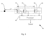
- FIG. 3 is a schematic block diagram of a microphone array system 48, according to a preferred embodiment of the present invention.
- System 48 comprises an array 50 of sound pressure sensors 52 and a processor 60, which processes signals received from the sensors in order to reduce the effect of noise or other interference present in the signals from the sensors.
- pressure sensors 52 are omnidirectional microphones having substantially similar characteristics and operating over the complete band of audible sound frequencies.
- pressure sensors 52 are unidirectional microphones.
- distances between sensors 52 are chosen so that signals generated by individual sensors, from a sound source 54 of interest emitting a plurality of frequencies, are distinguishable in terms of phase and power, while allowing the sensors to be in generally the same sound field, i.e., to be comparably affected by the same sound sources.
- distances between sensors 52 must also be small enough to prevent spatial aliasing in the received range of frequencies.
- sound source 54 is at a position within a middle distance range of approximately 3-100 cm from the center of array 50.
- sensors 52 are unidirectional, they are preferably oriented in substantially identical directions towards sound source 54.
- one of the sensors preferably the sensor farthest from sound source 54, may be oriented in the opposite direction in order, inter alia, to improve discrimination between sound coming from the direction of the sound source and sound coming from an opposite direction.
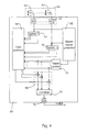
- Fig. 4 is a schematic block diagram illustrating the operation of processor 60, in accordance with a preferred embodiment of the present invention.
- Processor 60 may be implemented in an analog, a digital or a hybrid analog-digital form, by methods of electronic design and, as appropriate, software programming known in the art.
- Processor 60 comprises a master signal generator 62, a set of splitters 64, a gain controller 66, a gain reducer 68, a combiner 70, and a master signal splitter 72.
- processor 60 comprises a plurality of analog-to-digital converters 74 and a digital-to-analog converter 76.
- Converters 74 digitize signals from sensors 52 and transfer the respective digitized signals to splitters 64 and master signal generator 62.
- Digital-to-analog converter 76 outputs the signal from combiner 70 as an analog signal.
- processor 60 when processor 60 is implemented in an analog or in a hybrid analog-digital form, signals from sensors 52 are transferred directly to splitters 64 and master signal generator 62, and combiner 70 generates an analog output directly.
- Each splitter 64 comprises a set of band-pass filters, which receive signals from a respective sensor 52, split the signals into frequency bands using the filters, and transfer the split signals to gain controller 66.
- splitters 64 are implemented as a set of analog filters. Preferably, each filter covers approximately 1/3 of an octave, and the set is sufficient to cover the audible range of sound.
- splitters 64 are preferably implemented as a sequence of windowed FFT transforms with half-window overlap performed on every individual signal. Hanning windows, as are known in the art, are preferably used for this purpose. The sequences of complex coefficients resulting from the FFTs represent individual frequency band signals.
- Master signal generator 62 receives full-band signals from each sensor 52 and generates one output master signal. Master generator 62 preferably produces the output master signal such that the sound source of interest is enhanced compared to the signals from individual sensors, utilizing any suitable beam-forming strategy known in the art. For example, in Numerical Optimization of Non-adaptive Microphone Arrays, by Alexander Goldin, Proc. IEEE Int. Conf. on Acoustics, Speech and Signal Processing (1997), pages 507-510, the author describes how an enhanced signal may be generated as a sum of filtered signals from individual sensors. The filters are fixed and chosen in an array design stage during a numerical optimization procedure. The purpose of the optimization is to provide good directional characteristics with minimal off-axis frequency coloration of the enhanced signal. Alternatively, generator 62 may just use the signal from one of sensors 52, preferably a sensor oriented towards the sound source of interest, without altering the signal.
- the output signal from generator 62 is split by master signal splitter 72 into frequency bands to generate a master set of signals, which is output to gain controller 66.
- master splitter 72 is constructed and functions in substantially the same manner as each of splitters 64.
- Controller 66 operates by setting the gain of each particular frequency band according to a function of parameters of the master signal and the signals from individual sensors 52.
- a generalized gain function is given by the following equation:
- G i ( t ) is the gain for band i at an instant t
- k is the number of bands into which the signal is split
- m is the number of sensors in array 50
- j 1 ,.., k
- p j n ( t ) 1 ,.., k are instantaneous parameters of the signal from the n th sensor.
- the parameters represent respective amplitudes, powers, or phases of the signals in the given frequency bands.
- Gain controller 66 generates a gain for each of the k frequency bands depending on short-term power and phase information in the input signals. (A specific gain function is described in detail hereinbelow, with reference to Figs. 6, 7, and 8, whereby gain controller 66 assigns gains in the different bands produced by splitters 64 and splitter 72 according to whether the signal in a particular band comes from inside or outside a "sensitivity region," in front of array 50. In general, signals originating outside the sensitivity region are suppressed.) Each gain is directly applied to the respective master signal band in gain reducer 68, which multiplies each band by its respective gain. The separate output band signals are then combined to form one output signal in combiner 70. For an analog or hybrid implementation, combiner 70 is an analog mixer.
- combiner 70 is preferably a simple digital mixer. If a FFT is used in splitters 64 and 72, then an inverse FFT is used in combiner 70. Alternatively, combiner 70 may have a more complex structure, as is known in the art.
- Fig. 5 is a schematic block diagram showing the operation of a processor 80, in accordance with an alternative preferred embodiment of the present invention.
- processor 80 operates in substantially the same manner as processor 60, whereby components having the same numbers in processors 60 and 80 are constructed and function in substantially the same manner.
- Signals from sensors 52 are transferred to corresponding splitters 64.
- the transfer is direct if processor 80 is constructed as an analog or a hybrid embodiment.
- the transfer is via A/D converters 74 if processor 80 is a digital embodiment.
- each splitter transfers the split signals to gain controller 66 and to master signal generator 62.
- Generator 62 combines the split signals, using band-by-band addition or other processes known in the art, to generate a master set of signals in the frequency bands corresponding to those of splitters 64.
- the master set of signals is then transferred directly to gain controller 66 and gain reducer 68, so that master splitter 72 of processor 60 is not required.
- the remainder of the operation of processor 80 is substantially as described above with reference to processor 60.
- Fig. 6 is a schematic diagram showing the layout of a microphone array 90, applicable to a preferred embodiment of the present invention.
- the diagram illustrates a method for using instantaneous sound powers as the parameters of equation (1), to calculate a corresponding gain function.
- Array 90 comprises two omnidirectional sound sensors 92 lying on an axis 96 and separated by a distance 2D .
- a sound source 94 is located a distance L from the center of array 90, and subtends an angle ⁇ with axis 96.
- L 1 ( L sin( ⁇ )) 2 +( L cos( ⁇ )- D ) 2
- L 2 ( L sin( ⁇ )) 2 +( L cos( ⁇ )+ D ) 2
- angles ⁇ 1 and ⁇ 2 between axis 96 and the lines connecting sound source 94 to sensors 92 are given by:
- r 1 when -90° ⁇ ⁇ ⁇ 90°, i.e., the sound source is in front of the array.
- r also approaches 1 for all angles ⁇ when the distance L is large compared to D.
- Array 90 is positioned at the center of a 500 mm radius circle 102.
- a middle line 110 encloses a sensitivity region 106 defined by r ⁇ 0.6, and an inner line 120 encloses a sensitivity region 108 defined by r ⁇ 0.4.
- Lines 100, 110, and 120 are generated by solving equation (3) for L for the respective values of r c .
- the source of the sound is considered to be within the region, so that the gain G for the particular band should be theoretically set to unity.
- r > r c then the sound source is assumed to be outside the region, so that the gain G should be theoretically set to zero.
- a line 130 in the graph corresponds to a theoretical gain step function ⁇ (r,G)
- the step function is modified to have a generally continuous transition region 134, as illustrated by a curve 132.
- gain controller 66 calculates the ratio r of instantaneous powers in a particular frequency band.
- controller 66 utilizes a gain function of the form shown by line 132, Fig. 8, to set the gain of each band.
- the gains are applied to each band of the master signal in gain reducer 68, and the signals produced are combined in combiner 70, as described above, to produce the output signal.
- a 2 1 T 2 ( ⁇ 1 ) L 2 1 T 2 ( ⁇ 2 )
- L 2 2 T 2 ( ⁇ 1 ) T 2 ( ⁇ 2 ) • ( L sin( ⁇ )) 2 + ( L cos( ⁇ )- D ) 2 ( L sin( ⁇ )) 2 + ( L cos( ⁇ )+ D ) 2
- the angles ⁇ 1 , ⁇ 2 are computed according to equation (2).
- equation (5) can be used to generate a gain function corresponding to equation 1.
- Gain functions generated for three or more sensors are generally more stable when random fluctuations of the sound field occur in a closed environment.
- master signals produced by three or more sensors are generally enhanced compared to master signals produced by two sensors. For example, an average or maximal ratio between signal powers from adjacent sensors may be used to compute the gain function. Increasing the number of sensors is known to improve the directivity of the fixed array used to generate the master signal.
- Figs. 6, 7, and 8 uses instantaneous sound pressures as parameters for determining the gain function of equation (1).
- instantaneous phase differences between band signals may also be utilized to determine the gain function.
- the maximum allowable value of a phase difference from a source within a particular angular sector for a specific band, corresponding to the critical ratio of equation (4) is computed.
- a gain function similar to that described with reference to Fig. 8 is generated using phase differences as parameters, and is applied by gain controller 66 so as to generate the output signal.
- the gain in a given band is reduced if the actual phase difference is greater than the maximum allowable value.
- the present invention is not limited to the specific gain functions described hereinabove, and it will be appreciated that other gain functions, based on sound power, phase and/or other parameters, may also be used in microphone systems for the purpose of discriminating between sound sources by their distance range from the microphones.
Applications Claiming Priority (2)
| Application Number | Priority Date | Filing Date | Title |
|---|---|---|---|
| US342957 | 1982-01-26 | ||
| US34295799A | 1999-06-29 | 1999-06-29 |
Publications (1)
| Publication Number | Publication Date |
|---|---|
| EP1065909A2 true EP1065909A2 (fr) | 2001-01-03 |
Family
ID=23344036
Family Applications (1)
| Application Number | Title | Priority Date | Filing Date |
|---|---|---|---|
| EP20000305471 Withdrawn EP1065909A2 (fr) | 1999-06-29 | 2000-06-29 | Système de microphones suppresseur de bruit |
Country Status (2)
| Country | Link |
|---|---|
| EP (1) | EP1065909A2 (fr) |
| JP (1) | JP2001045592A (fr) |
Cited By (9)
| Publication number | Priority date | Publication date | Assignee | Title |
|---|---|---|---|---|
| WO2003009636A2 (fr) * | 2001-07-17 | 2003-01-30 | Clarity, Llc | Acquisition sonore directionnelle |
| WO2003015459A2 (fr) * | 2001-08-10 | 2003-02-20 | Rasmussen Digital Aps | Systeme de traitement du son presentant une reponse du gradient arbitraire |
| DE102004011149B3 (de) * | 2004-03-08 | 2005-11-10 | Infineon Technologies Ag | Mikrophon und Verfahren zur Herstellung eines Mikrophons |
| US7274794B1 (en) | 2001-08-10 | 2007-09-25 | Sonic Innovations, Inc. | Sound processing system including forward filter that exhibits arbitrary directivity and gradient response in single wave sound environment |
| US20100232620A1 (en) * | 2007-11-26 | 2010-09-16 | Fujitsu Limited | Sound processing device, correcting device, correcting method and recording medium |
| US8036888B2 (en) | 2006-05-26 | 2011-10-11 | Fujitsu Limited | Collecting sound device with directionality, collecting sound method with directionality and memory product |
| US8462962B2 (en) | 2008-02-20 | 2013-06-11 | Fujitsu Limited | Sound processor, sound processing method and recording medium storing sound processing program |
| US8565459B2 (en) | 2006-11-24 | 2013-10-22 | Rasmussen Digital Aps | Signal processing using spatial filter |
| US8923529B2 (en) | 2008-08-29 | 2014-12-30 | Biamp Systems Corporation | Microphone array system and method for sound acquisition |
Families Citing this family (1)
| Publication number | Priority date | Publication date | Assignee | Title |
|---|---|---|---|---|
| JP4676920B2 (ja) * | 2006-05-12 | 2011-04-27 | 日本電信電話株式会社 | 信号分離装置、信号分離方法、信号分離プログラム及び記録媒体 |
-
2000
- 2000-06-29 JP JP2000197129A patent/JP2001045592A/ja active Pending
- 2000-06-29 EP EP20000305471 patent/EP1065909A2/fr not_active Withdrawn
Cited By (15)
| Publication number | Priority date | Publication date | Assignee | Title |
|---|---|---|---|---|
| WO2003009636A3 (fr) * | 2001-07-17 | 2004-06-17 | Clarity Llc | Acquisition sonore directionnelle |
| WO2003009636A2 (fr) * | 2001-07-17 | 2003-01-30 | Clarity, Llc | Acquisition sonore directionnelle |
| US7142677B2 (en) | 2001-07-17 | 2006-11-28 | Clarity Technologies, Inc. | Directional sound acquisition |
| US7274794B1 (en) | 2001-08-10 | 2007-09-25 | Sonic Innovations, Inc. | Sound processing system including forward filter that exhibits arbitrary directivity and gradient response in single wave sound environment |
| WO2003015459A3 (fr) * | 2001-08-10 | 2003-11-20 | Rasmussen Digital Aps | Systeme de traitement du son presentant une reponse du gradient arbitraire |
| WO2003015459A2 (fr) * | 2001-08-10 | 2003-02-20 | Rasmussen Digital Aps | Systeme de traitement du son presentant une reponse du gradient arbitraire |
| DE102004011149B3 (de) * | 2004-03-08 | 2005-11-10 | Infineon Technologies Ag | Mikrophon und Verfahren zur Herstellung eines Mikrophons |
| US8036888B2 (en) | 2006-05-26 | 2011-10-11 | Fujitsu Limited | Collecting sound device with directionality, collecting sound method with directionality and memory product |
| US8565459B2 (en) | 2006-11-24 | 2013-10-22 | Rasmussen Digital Aps | Signal processing using spatial filter |
| US8965003B2 (en) | 2006-11-24 | 2015-02-24 | Rasmussen Digital Aps | Signal processing using spatial filter |
| US20100232620A1 (en) * | 2007-11-26 | 2010-09-16 | Fujitsu Limited | Sound processing device, correcting device, correcting method and recording medium |
| US8615092B2 (en) * | 2007-11-26 | 2013-12-24 | Fujitsu Limited | Sound processing device, correcting device, correcting method and recording medium |
| US8462962B2 (en) | 2008-02-20 | 2013-06-11 | Fujitsu Limited | Sound processor, sound processing method and recording medium storing sound processing program |
| US8923529B2 (en) | 2008-08-29 | 2014-12-30 | Biamp Systems Corporation | Microphone array system and method for sound acquisition |
| US9462380B2 (en) | 2008-08-29 | 2016-10-04 | Biamp Systems Corporation | Microphone array system and a method for sound acquisition |
Also Published As
| Publication number | Publication date |
|---|---|
| JP2001045592A (ja) | 2001-02-16 |
Similar Documents
| Publication | Publication Date | Title |
|---|---|---|
| KR101449433B1 (ko) | 마이크로폰을 통해 입력된 사운드 신호로부터 잡음을제거하는 방법 및 장치 | |
| US6192134B1 (en) | System and method for a monolithic directional microphone array | |
| US8112272B2 (en) | Sound source separation device, speech recognition device, mobile telephone, sound source separation method, and program | |
| US7359504B1 (en) | Method and apparatus for reducing echo and noise | |
| KR101456866B1 (ko) | 혼합 사운드로부터 목표 음원 신호를 추출하는 방법 및장치 | |
| US7613309B2 (en) | Interference suppression techniques | |
| JP3521914B2 (ja) | 超指向性マイクロホンアレイ | |
| EP1278395B1 (fr) | Réseau de microphones adaptatifs différentiels du second ordre | |
| US6668062B1 (en) | FFT-based technique for adaptive directionality of dual microphones | |
| US9456275B2 (en) | Cardioid beam with a desired null based acoustic devices, systems, and methods | |
| JP4588966B2 (ja) | 雑音低減のための方法 | |
| EP1489596B1 (fr) | Procédé et dispositif de détection de l'activité vocale | |
| RU2434262C2 (ru) | Улучшение сигнала вектора ближнего поля | |
| KR101715779B1 (ko) | 음원 신호 처리 장치 및 그 방법 | |
| EP1116961A2 (fr) | Procédé et dispositif de localisation des personnes parlants | |
| US9232309B2 (en) | Microphone array processing system | |
| US9521486B1 (en) | Frequency based beamforming | |
| US20060013412A1 (en) | Method and system for reduction of noise in microphone signals | |
| WO1995008248A1 (fr) | Systeme de reduction du bruit dans une prothese auditive stereophonique | |
| EP1081985A2 (fr) | Système de traitement à réseau de microphones pour environnements bruyants à trajets multiples | |
| US8615392B1 (en) | Systems and methods for producing an acoustic field having a target spatial pattern | |
| WO2003036614A2 (fr) | Systeme et appareil de communication vocale et de reconnaissance vocale | |
| JP2001510001A (ja) | 複数ソースを伴うオーディオ処理装置 | |
| CN111078185A (zh) | 录制声音的方法及设备 | |
| US8275147B2 (en) | Selective shaping of communication signals |
Legal Events
| Date | Code | Title | Description |
|---|---|---|---|
| PUAI | Public reference made under article 153(3) epc to a published international application that has entered the european phase |
Free format text: ORIGINAL CODE: 0009012 |
|
| AK | Designated contracting states |
Kind code of ref document: A2 Designated state(s): AT BE CH CY DE DK ES FI FR GB GR IE IT LI LU MC NL PT SE |
|
| AX | Request for extension of the european patent |
Free format text: AL;LT;LV;MK;RO;SI |
|
| RAP1 | Party data changed (applicant data changed or rights of an application transferred) |
Owner name: DECKE UND DACH GMBH |
|
| RIN1 | Information on inventor provided before grant (corrected) |
Inventor name: DECKE UND DACH GMBH |
|
| STAA | Information on the status of an ep patent application or granted ep patent |
Free format text: STATUS: THE APPLICATION IS DEEMED TO BE WITHDRAWN |
|
| 18D | Application deemed to be withdrawn |
Effective date: 20041231 |