EP1065794A2 - Direct sequence CDMA receiver having a delay profile producer with an interpolation function - Google Patents
Direct sequence CDMA receiver having a delay profile producer with an interpolation function Download PDFInfo
- Publication number
- EP1065794A2 EP1065794A2 EP00113162A EP00113162A EP1065794A2 EP 1065794 A2 EP1065794 A2 EP 1065794A2 EP 00113162 A EP00113162 A EP 00113162A EP 00113162 A EP00113162 A EP 00113162A EP 1065794 A2 EP1065794 A2 EP 1065794A2
- Authority
- EP
- European Patent Office
- Prior art keywords
- despreading
- received data
- spreading code
- delay profile
- timing
- Prior art date
- Legal status (The legal status is an assumption and is not a legal conclusion. Google has not performed a legal analysis and makes no representation as to the accuracy of the status listed.)
- Granted
Links
Images




Classifications
-
- H—ELECTRICITY
- H04—ELECTRIC COMMUNICATION TECHNIQUE
- H04B—TRANSMISSION
- H04B1/00—Details of transmission systems, not covered by a single one of groups H04B3/00 - H04B13/00; Details of transmission systems not characterised by the medium used for transmission
- H04B1/69—Spread spectrum techniques
- H04B1/707—Spread spectrum techniques using direct sequence modulation
- H04B1/7097—Interference-related aspects
- H04B1/711—Interference-related aspects the interference being multi-path interference
- H04B1/7113—Determination of path profile
-
- H—ELECTRICITY
- H04—ELECTRIC COMMUNICATION TECHNIQUE
- H04B—TRANSMISSION
- H04B1/00—Details of transmission systems, not covered by a single one of groups H04B3/00 - H04B13/00; Details of transmission systems not characterised by the medium used for transmission
- H04B1/69—Spread spectrum techniques
- H04B1/707—Spread spectrum techniques using direct sequence modulation
- H04B1/709—Correlator structure
- H04B1/7093—Matched filter type
Definitions
- the present invention relates to a direct sequence CDMA receiver, and more particularly to a receiver of the CDMA (Code Division Multiple Access) system that performs despreading demodulation using a spreading code that is contained in the received signal.
- CDMA Code Division Multiple Access
- the leading position of the spreading code contained within the received signal must be detected and despreading demodulation must be performed using the spreading code that is synchronized with this leading position.
- correlation values with the spreading code are found using a portion having a known data sequence, such as pilot symbols or a preamble data sequence that is periodically inserted, and timings are found for which these correlation values are high.
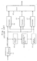
- Fig. 1 shows the configuration of a receiver.
- a signal received by an antenna (not shown) is demodulated to convert to a baseband signal, and which is sampled at twice the chip rate by A/D (analog/digital) converter 41.
- Correlation values between the spreading code and the sampled received data are then found by matched filter 42.
- delay profile production unit 43 delay profiles are sought from the correlation values of the sampling interval of received data obtained by matched filter 42.
- timing detector 44 prescribed locations are selected in descending order from the largest value among the correlation values of this delay profile, and timing signals are generated based on the timings of each of the selected values.
- despreader 45 - 47 the received data are despread using a spreading code that is synchronized with these timing signals, and data are obtained through RAKE/diversity mixing at mixer 48.
- matched filter 42 comprises received signal shift register 51, spreading code register 52, multipliers 53, and adder 54.
- Received signal shift register 51 receives and shifts the received signal.
- Spreading code register 52 sets a spreading code sequence of the same bit length as this received signal shift register 51.
- Multipliers 53 multiply the values of received signal shift register 51 and spreading code register 52.
- Adder 54 adds the output signals of multipliers 53.
- the received signal sequence is constituted by a known portion (pilot portion) and a data portion that is not know, and is sampled at, for example, twice the chip period of the spreading code, and through A/D conversion, becomes a digital value between -1.0 - +1.0.
- received signal shift register 51 shifts the received signal each 1/2 chip period in accordance with the sampling period of the received signal.
- the delay profile varies with fading or movement of a mobile terminal and has a plurality of maximum values, and the timing of which is extracted by timing detector 44. If the delay profile is represented as shown in Fig. 3, the correlation values in the delay profile are selected in descending order of size and the timing at which each of these correlation values was obtained is reported to despreaders 45 - 47 by means of respectively different timing signals.
- Japanese Patent Laid-open No. 178386/98 and Japanese Patent Laid-open No. 336072/98 each disclose an example of the aforementioned CDMA receiver.
- the spreading code and received data must be reliably and accurately synchronized, and it is well known that reception characteristics deteriorate drastically with a variance in synchronization of just 1/4 chip. The deterioration is particularly noticeable in the case of a low spreading rate, such as in high-speed data transfer.
- the direct sequence CDMA receiver comprises an analog/digital conversion means, a matched filter, and a delay profile production means.
- the analog/digital conversion means samples, at twice the chip rate, a baseband signal obtained by demodulating a signal received by way of an antenna.
- the matched filter acquires correlation values of the received data sampled by the analog/digital conversion means and a spreading code while time-shifting said received data.
- the delay profile production means interpolates correlation values found by the matched filter, and finds the delay profiles from the interpolated correlation values. That is, when establishing synchronization on the receiving side, correlation values are found between a spreading code composed of 1/-1 data and then received data, and delay profile is produced using the correlation values of the sampling period. The timings of peaks in the correlation values in the delay profile are then obtained to realize synchronization between the received data and the spreading code. The accuracy of synchronization is therefore dependent on the sampling interval of the received data.
- the direct sequence CDMA receiver inputs a signal received by an antenna and converted to a baseband signal, and samples the input at twice the chip rate in an A/D converter. Thereafter, correlation values with the received data are then found by means of the matched filter using the 1/-1 spreading code and are interpolated by means of, for example, a filter in the delay profile production means having an interpolation function. These interpolated data are then used to provide delay profiles as a continuous characteristic. As a result, the timing of peaks in the delay profiles can also be obtained with higher accuracy in a timing detector irrespective of a sampling period.
- the correlation values in a delay profile are selected in descending order of size, the timings at which these correlation values were obtained are extracted, and respectively different timing signals are supplied to despreader.
- the despreaders are not limited to three in number, and may one or more.
- the spreading code is interpolated to synchronize with these timing signals, and the received data are despread using the interpolated values.
- the despread signals are RAKE/diversity mixed in a mixer to obtain data.
- Synchronization of despread timing can thus be accurately achieved without increasing the A/D conversion sampling rate of the received data, thereby improving reception characteristics.
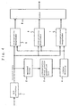
- a direct sequence CDMA receiver (hereinbelow referred to as “receiver") according to the first embodiment comprises A/D (analog/digital) converter 1, matched filter 2, interpolative delay profile production unit 3, timing detector 4, interpolative despreaders 5 - 7, and mixer 8.
- A/D converter 1 samples a baseband signal obtained by demodulating a signal received by an antenna (not shown) at twice the chip rate.
- Matched filter 2 finds correlation values between a spreading code and received data sampled in A/D converter 1.
- Interpolative delay profile production unit 3 interpolates the correlation values found by matched filter 2 at, for example, 1/16 chip interval, which is equivalent to eight times the sampling rate.
- Interpolative delay profile production unit 3 finds delay profiles based on the interpolated correlation values.
- Timing detector 4 selects a predetermined number of values in descending order of size from the peak value among the correlation values of these delay profiles, and generates timing signals based on the timings of each of the selected values.
- the receiver then despreads the received data at interpolative despreaders 5 - 7 using a spreading code that is synchronized with these timing signals, and obtains data through RAKE/diversity mixing at mixer 8.
- Interpolation performed by interpolative delay profile production unit 3 may only apply to the higher portions of the correlation values, and the time intervals after interpolation may be appropriately shortened or lengthened.
- the present embodiment has three interpolative despreaders, but this number may be increased or decreased according to the use environment.
- matched filter 2 is made up of received signal shift register 11, spreading code register 12, multipliers 13, and adder 14.
- Received signal shift register 11 shifts received signals received by matched filter 2.
- Spreading code register 12 sets a spreading code sequence of the same bit length as received signal shift register 11.
- Multipliers 13 multiply the values of received signal shift register 11 and spreading code register 12 together, Adder 14 adds together the output signals of multipliers 13.
- Interpolative delay profile production unit 3 includes an interpolator 15 that interpolates the output signals of adder 14. Although not shown in the figure, interpolative delay profile production unit 3 includes a delay profile production unit that produces delay profiles based on the output of interpolator 15.
- the received signals are composed of a known transmission data string and a data portion that is unknown.
- pilot symbols which are a number of symbols in which the transmission data sequence is already known, come at the head, and these pilot symbols are followed by data symbols.
- interpolative despreader 5 comprises received signal shift register 21, spreading code register 22, multipliers 23, and adder 24.
- Received signal shift register 21 shifts received signals received by interpolative despreader 5.
- Spreading code register 22 sets a spreading code sequence of the same bit length as received signal shift register 21.
- Multipliers 23 multiply the values of received signal shift register 21 and spreading code register 22 together.
- Adder 24 adds together the output signals of multipliers 23.
- interpolative despreaders 6 and 7 have the same construction as interpolative despreader 5.
- Received signals are sampled at twice the chip period of the spreading code and then undergo A/D conversion to become digital values between -1.0 - +1.0.
- Received signal shift register 21 is, for example, twice the length of the spread rate, and shifts received signals one at a time each 1/2 chip period in accordance with the sampling period of the received signals.
- the output signals of each stage of this received signal shift register 11 and each bit of the spreading code sequence that is set by spreading code register 12 are multiplied at multipliers 13 for each shift, and the results of multiplication are added together at adder 14 to obtain correlation values.
- These correlation values are interpolated at interpolator 15 using, for example, a FIR (Finite Impulse Response) low-pass interpolation filter.
- the correlation values are extended to a suitable length by inserting zeros between the original correlation value data values without altering the original data.
- a symmetrical FIR filter is designed such that the mean square error between the interpolated points and ideal points is minimized.
- the filter is applied to the correlation value data in which zeros have been inserted to produce interpolated values.
- a delay profile is obtained having peaks in the correlation values at t0, t1, t2, as shown in Fig. 6.
- the accuracy of the delay profile can be improved by demodulating the despreading pilot symbols by the transmission data sequence of the pilot symbols and adding.
- the accuracy of the delay profile can be further improved by carrying out weighted averaging using another known portion.
- Timing detector 4 selects a predetermined number of values in descending order of the correlation values of this delay profile and outputs timing signals based on each of the selected timings to a respective one of interpolative despreaders 5 - 7. If the delay profile is represented as shown in Fig. 6, timing detector 4 extracts the timings t0, t1 and t2.
- Interpolative despreaders 5 - 7 resample the received data based on these timing signals and perform despreading of the received data using a spreading code that is synchronized with the resampled received data.
- Mixer 8 subjects the received data that have been despread by interpolative despreaders 5 - 7 to RAKE/diversity mixing to obtain data.
- a direct sequence CDMA receiver will be next described.
- the timing of a sample was adjusted by resampling received data.
- received data need not be resampled if the value of a spreading code shift register is changed to a real number value (a complex number if spread is, for example, QPSK (Quadrature Phase Shift Keying) instead of 1/0/-1, as shown in Fig. 8.
- QPSK Quadrature Phase Shift Keying
- interpolative despreader 9 according to the second embodiment of the present invention comprises received signal shift register 31, coefficient operation unit 32, filter coefficient register 33 having the same register length as received signal shift register 31, multipliers 34, and adder 35.
- Received signal shift register 31 receives and shifts received signals.
- Coefficient operation unit 32 operates the coefficient of a filter based on the spreading code and timing signals.
- Multipliers 34 multiply the values of received signal shift register 31 and filter coefficient register 33, and adder 35 adds the output signals of multipliers 34.
- the receiver according to the second embodiment of the present invention has the same construction as the receiver according to the first embodiment of the present invention shown in Fig. 4, and the operation is also the same as that of the first embodiment of the present invention.
- the spread rate portion of s(n) ⁇ R(n) should be added, and if the spread rate is 4, it can
- This operation merely involves cutting the spreading code into symbol units and then employing the filter used during resampling in the first embodiment of the present invention.
- Received signals are thus applied to received signal shift register 31, coefficient operation unit 32 operates the coefficient of the filter based on the spreading code and timing signals and sets this coefficient in filter coefficient register 33, and multipliers 34 multiply the values of received signal shift register 31 and filter coefficient register 33. Adder 35 then adds the output signals of multipliers 34 to obtain a correlation value for one symbol.
- a 1-symbol portion of received data is applied to received signal shift register 31, coefficient operation unit 32 operates the next filter coefficient based on the spreading code and timing signals and sets this coefficient in filter coefficient register 33, and multipliers 34 multiply the values of received signal shift register 31 and filter coefficient register 33. Adder 35 then adds the output signals of multipliers 34 to obtain the next correlation value for one symbol. Following detection, the thus-obtained symbol period of correlation values undergo RAKE/diversity mixing to obtain the transmission sequence.
- the process for finding a filter coefficient is added in the present embodiment, and the length of received signal shift register 31 and filter coefficient register 33 is increased by just -1 over the length of the filter used during resampling in the first embodiment of the present invention. Nevertheless, since these processes are the symbol period, the processing load is lightened by the lack of the resampling process of the first embodiment of the present invention, which is carried out chip by chip.
Landscapes
- Engineering & Computer Science (AREA)
- Computer Networks & Wireless Communication (AREA)
- Signal Processing (AREA)
- Synchronisation In Digital Transmission Systems (AREA)
- Radio Transmission System (AREA)
Abstract
Description
Claims (10)
- A direct sequence CDMA receiver for performing despreading of received data based on a delay profile produced from said received data, comprising:analog/digital conversion means for sampling at twice the chip rate a baseband signal obtained by demodulating a signal received from an antenna;a matched filter for finding correlation values of received data that has been sampled by said analog/digital conversion means and a spreading code while shifting said received data in time; anda delay profile production means for interpolating correlation values found by said matched filter and finding said delay profile from the interpolated correlation values.
- A receiver according to claim 1, further comprising:timing detection means for selecting, in descending order of size, delay profiles found by said delay profile production means to extract each timing;despread processing means for interpolating a spreading code to synchronize with timing signals detected by said timing detection means and using these interpolated values to carry out despreading of received data; andmixing means for subjecting signals that have undergone despreading by said despreader to RAKE/diversity mixing to obtain data.
- A receiver according to claim 2, wherein said despreading means includes means for sampling received data based on timing signals detected by said timing detection means and using a spreading code that has been synchronized with resampled received data to subject said received data to despreading.
- A receiver according to claim 2 or 3, wherein it includes one or more of said despreading means.
- A receiver according to claim 1, 2, 3 or 4, wherein said despreading means includes coefficient operation means for operating a filter coefficient from timing signals detected by said timing detection means and said spreading code, and a means for despreading based on said filter coefficient.
- A receiver according to claim 1, 2, 3, 4 or 5, wherein said delay profile production means produces interpolated correlation values by using a filter in which zeros are inserted into interpolated correlation values.
- A receiver according to claim 6, further comprising:timing detection means for selecting, in descending order of size, delay profiles found by said delay profile production means to extract each timings;despreading means for interpolating a spreading code to synchronize with timing signals detected by said timing detection means, and performing despreading of received data using the interpolated values;mixing means for obtaining data by carrying out RAKE/diversity mixing of signals that have undergone despreading by said despreading means.
- A receiver according to claim 7, wherein said despreading means includes means for resampling received data based on timing signals detected by said timing detection means, and for carrying out despreading of said received data by using a spreading code that is synchronized with the resampled received data.
- A receiver according to claim 7 or 8 that includes one or more of said despreading means.
- A receiver according to claim 6, 7, 8 or 9, wherein said despreading means includes coefficient operation means for operating a filter coefficient from timing signals detected by said timing detection means and said spreading code, and a means for despreading based on said filter coefficient.
Applications Claiming Priority (2)
| Application Number | Priority Date | Filing Date | Title |
|---|---|---|---|
| JP18455799 | 1999-06-30 | ||
| JP18455799A JP3322243B2 (en) | 1999-06-30 | 1999-06-30 | Direct spread CDMA receiver |
Publications (3)
| Publication Number | Publication Date |
|---|---|
| EP1065794A2 true EP1065794A2 (en) | 2001-01-03 |
| EP1065794A3 EP1065794A3 (en) | 2003-01-02 |
| EP1065794B1 EP1065794B1 (en) | 2006-03-22 |
Family
ID=16155299
Family Applications (1)
| Application Number | Title | Priority Date | Filing Date |
|---|---|---|---|
| EP20000113162 Expired - Lifetime EP1065794B1 (en) | 1999-06-30 | 2000-06-29 | Direct sequence CDMA receiver having a delay profile producer with an interpolation function |
Country Status (4)
| Country | Link |
|---|---|
| US (1) | US6816542B1 (en) |
| EP (1) | EP1065794B1 (en) |
| JP (1) | JP3322243B2 (en) |
| DE (1) | DE60026760T2 (en) |
Cited By (6)
| Publication number | Priority date | Publication date | Assignee | Title |
|---|---|---|---|---|
| EP1376886A1 (en) * | 2002-06-17 | 2004-01-02 | Agilent Technologies, Inc. - a Delaware corporation - | Rake receiver delay line design |
| SG108257A1 (en) * | 2001-06-15 | 2005-01-28 | Oki Electric Ind Co Ltd | Receiving circuit |
| WO2005076493A1 (en) * | 2004-02-02 | 2005-08-18 | Analog Devices, Inc. | Post despreading interpolation in cdma systems |
| WO2007128187A1 (en) * | 2006-05-08 | 2007-11-15 | Zte Corporation | A multi- antennae multiplexing interpolation device |
| US7372895B2 (en) | 2004-12-08 | 2008-05-13 | Telefonaktiebolaget Lm Ericsson (Publ) | Method of and system for delay estimation with minimized finger allocation |
| US7480356B2 (en) | 2004-12-08 | 2009-01-20 | Telefonaktiebolaget L M Ericsson (Publ) | Method of and system for path selection in rich multipath conditions |
Families Citing this family (11)
| Publication number | Priority date | Publication date | Assignee | Title |
|---|---|---|---|---|
| JP3566895B2 (en) * | 2000-02-15 | 2004-09-15 | 株式会社エヌ・ティ・ティ・ドコモ | Leading wave position detecting device, receiving device, leading position detecting device, leading wave position detecting method, and leading position detecting method |
| US6973146B1 (en) * | 2000-08-29 | 2005-12-06 | Lucent Technologies Inc. | Resampler for a bit pump and method of resampling a signal associated therewith |
| GB0028392D0 (en) * | 2000-11-22 | 2001-01-03 | Koninkl Philips Electronics Nv | A rake receiver |
| GB0110464D0 (en) * | 2001-04-28 | 2001-06-20 | Koninkl Philips Electronics Nv | A method of detecting and a receiver for a spread spectrum signal |
| GB0110465D0 (en) * | 2001-04-28 | 2001-06-20 | Koninkl Philips Electronics Nv | Spread spectrum reciever and method of detection |
| US7912154B2 (en) * | 2005-01-31 | 2011-03-22 | Zte Corporation | Baseband process method based on doubling sampling |
| US8064556B2 (en) | 2005-09-15 | 2011-11-22 | Qualcomm Incorporated | Fractionally-spaced equalizers for spread spectrum wireless communication |
| EP1931056A4 (en) * | 2005-09-28 | 2014-04-23 | Nec Corp | Modulator, filter, filter gain control method, and code modulating method |
| EP2003789B1 (en) * | 2006-03-31 | 2016-05-18 | Fujitsu Limited | Cdma receiver and cdma receiving method |
| US8162191B2 (en) | 2008-04-21 | 2012-04-24 | Shimano Inc. | Bicycle battery holder |
| TWI477746B (en) * | 2013-12-27 | 2015-03-21 | Realtek Semiconductor Corp | Temperature insensitive testing device and method |
Family Cites Families (16)
| Publication number | Priority date | Publication date | Assignee | Title |
|---|---|---|---|---|
| JP3194752B2 (en) | 1991-01-31 | 2001-08-06 | パイオニア株式会社 | PCM digital audio signal playback device |
| JPH0758669A (en) | 1993-08-11 | 1995-03-03 | Fujitsu Ltd | Digital matched filter |
| US5615232A (en) * | 1993-11-24 | 1997-03-25 | Novatel Communications Ltd. | Method of estimating a line of sight signal propagation time using a reduced-multipath correlation function |
| JP3337613B2 (en) | 1996-03-05 | 2002-10-21 | シャープ株式会社 | Spread spectrum communication system |
| JP2751959B2 (en) * | 1996-07-15 | 1998-05-18 | 日本電気株式会社 | Reception timing detection circuit of CDMA receiver |
| JP3800363B2 (en) | 1996-12-18 | 2006-07-26 | 富士通株式会社 | CDMA system, transmission / reception apparatus thereof, and random access method |
| JPH10271034A (en) | 1997-03-26 | 1998-10-09 | Matsushita Electric Ind Co Ltd | CDMA mobile communication receiver |
| JP3503409B2 (en) | 1997-04-10 | 2004-03-08 | 株式会社日立製作所 | Spread spectrum receiver |
| JPH1141141A (en) | 1997-05-21 | 1999-02-12 | Mitsubishi Electric Corp | Spread spectrum signal receiving method and spread spectrum signal receiving apparatus |
| JP3462364B2 (en) | 1997-06-02 | 2003-11-05 | 株式会社エヌ・ティ・ティ・ドコモ | RAKE receiver in direct spread CDMA transmission system |
| JP3095065B2 (en) * | 1997-09-11 | 2000-10-03 | 日本電気株式会社 | Rake receiving method and rake receiving apparatus for spread spectrum signal |
| JP3305639B2 (en) * | 1997-12-24 | 2002-07-24 | 株式会社エヌ・ティ・ティ・ドコモ | RAKE receiver in direct spread CDMA transmission system |
| JP3891373B2 (en) * | 1998-03-26 | 2007-03-14 | ソニー株式会社 | Demodulator and demodulation method |
| SE9802109D0 (en) * | 1998-06-12 | 1998-06-12 | Ericsson Telefon Ab L M | One-bit correlator rake receiver |
| JP3816684B2 (en) | 1999-02-24 | 2006-08-30 | 三菱電機株式会社 | Spread spectrum receiver |
| US6567482B1 (en) * | 1999-03-05 | 2003-05-20 | Telefonaktiebolaget Lm Ericsson (Publ) | Method and apparatus for efficient synchronization in spread spectrum communications |
-
1999
- 1999-06-30 JP JP18455799A patent/JP3322243B2/en not_active Expired - Fee Related
-
2000
- 2000-06-29 US US09/607,018 patent/US6816542B1/en not_active Expired - Fee Related
- 2000-06-29 EP EP20000113162 patent/EP1065794B1/en not_active Expired - Lifetime
- 2000-06-29 DE DE2000626760 patent/DE60026760T2/en not_active Expired - Fee Related
Cited By (7)
| Publication number | Priority date | Publication date | Assignee | Title |
|---|---|---|---|---|
| SG108257A1 (en) * | 2001-06-15 | 2005-01-28 | Oki Electric Ind Co Ltd | Receiving circuit |
| EP1376886A1 (en) * | 2002-06-17 | 2004-01-02 | Agilent Technologies, Inc. - a Delaware corporation - | Rake receiver delay line design |
| WO2005076493A1 (en) * | 2004-02-02 | 2005-08-18 | Analog Devices, Inc. | Post despreading interpolation in cdma systems |
| US7372895B2 (en) | 2004-12-08 | 2008-05-13 | Telefonaktiebolaget Lm Ericsson (Publ) | Method of and system for delay estimation with minimized finger allocation |
| US7480356B2 (en) | 2004-12-08 | 2009-01-20 | Telefonaktiebolaget L M Ericsson (Publ) | Method of and system for path selection in rich multipath conditions |
| WO2007128187A1 (en) * | 2006-05-08 | 2007-11-15 | Zte Corporation | A multi- antennae multiplexing interpolation device |
| CN101072213B (en) * | 2006-05-08 | 2011-05-25 | 中兴通讯股份有限公司 | Multi antenna multiplexing interpolation device |
Also Published As
| Publication number | Publication date |
|---|---|
| JP2001016136A (en) | 2001-01-19 |
| EP1065794A3 (en) | 2003-01-02 |
| JP3322243B2 (en) | 2002-09-09 |
| EP1065794B1 (en) | 2006-03-22 |
| DE60026760D1 (en) | 2006-05-11 |
| US6816542B1 (en) | 2004-11-09 |
| DE60026760T2 (en) | 2006-09-07 |
Similar Documents
| Publication | Publication Date | Title |
|---|---|---|
| US6816542B1 (en) | Direct sequence CDMA receiver having a delay profile producer with an interpolation function | |
| EP0318685B1 (en) | Phase coherent TDMA quadrature receiver for multipath fading channels | |
| US7106784B2 (en) | Universal rake receiver | |
| US5936999A (en) | Receiver and method for generating spreading codes in a receiver | |
| KR100220140B1 (en) | Apparatus and Method for Initial Synchronization of Spread Spectrum Codes in CDM Transmission System | |
| EP0318686B1 (en) | TDMA Radio system employing BPSK synchronisation for QPSK signals subject to random phase variation and multipath fading | |
| EP1121767B1 (en) | A cdma receiver that shares a tracking device among multiple rake branches | |
| US20090022212A1 (en) | Cdma receiving apparatus and cdma receiving method | |
| JP3443113B2 (en) | Wireless receiving apparatus and wireless receiving method | |
| JPH1141141A (en) | Spread spectrum signal receiving method and spread spectrum signal receiving apparatus | |
| KR20010062214A (en) | Code division multiple access system and method of operation with improved signal acquisition and processing | |
| US6111910A (en) | Maximal correlation symbol estimation demodulator | |
| EP0798870B1 (en) | Receiving apparatus for spectrum spread system | |
| CA2112151C (en) | Digital data demodulating apparatus | |
| EP2011245A1 (en) | Baseband sample selection | |
| US20040097204A1 (en) | Multi-subscriber detection using a rake receiver structure | |
| US20010012316A1 (en) | Rake receiver with low pass filer | |
| US6959035B2 (en) | Post-correlation interpolation for delay locked loops | |
| JP2000244367A (en) | Spread spectrum receiver | |
| KR100430527B1 (en) | Rake receiver capable of compensating channel estimating delay | |
| JP3190268B2 (en) | RAKE receiver | |
| WO2003084080A2 (en) | System and method for signal time alignment using programmable matched filter coefficients | |
| Baltersee et al. | Performance bounds for a UMTS RAKE receiver with imperfect timing synchronisation | |
| JPH03145833A (en) | Demodulator for spread spectrum signal | |
| Soltanian et al. | A Novel Rake Receiver Architecture Based on Interpolation Techniques |
Legal Events
| Date | Code | Title | Description |
|---|---|---|---|
| PUAI | Public reference made under article 153(3) epc to a published international application that has entered the european phase |
Free format text: ORIGINAL CODE: 0009012 |
|
| AK | Designated contracting states |
Kind code of ref document: A2 Designated state(s): AT BE CH CY DE DK ES FI FR GB GR IE IT LI LU MC NL PT SE |
|
| AX | Request for extension of the european patent |
Free format text: AL;LT;LV;MK;RO;SI |
|
| PUAL | Search report despatched |
Free format text: ORIGINAL CODE: 0009013 |
|
| AK | Designated contracting states |
Kind code of ref document: A3 Designated state(s): AT BE CH CY DE DK ES FI FR GB GR IE IT LI LU MC NL PT SE |
|
| AX | Request for extension of the european patent |
Free format text: AL;LT;LV;MK;RO;SI |
|
| 17P | Request for examination filed |
Effective date: 20021126 |
|
| AKX | Designation fees paid |
Designated state(s): DE FR GB IT |
|
| 17Q | First examination report despatched |
Effective date: 20040428 |
|
| GRAP | Despatch of communication of intention to grant a patent |
Free format text: ORIGINAL CODE: EPIDOSNIGR1 |
|
| GRAS | Grant fee paid |
Free format text: ORIGINAL CODE: EPIDOSNIGR3 |
|
| GRAA | (expected) grant |
Free format text: ORIGINAL CODE: 0009210 |
|
| AK | Designated contracting states |
Kind code of ref document: B1 Designated state(s): DE FR GB IT |
|
| REG | Reference to a national code |
Ref country code: GB Ref legal event code: FG4D |
|
| REF | Corresponds to: |
Ref document number: 60026760 Country of ref document: DE Date of ref document: 20060511 Kind code of ref document: P |
|
| ET | Fr: translation filed | ||
| PLBE | No opposition filed within time limit |
Free format text: ORIGINAL CODE: 0009261 |
|
| STAA | Information on the status of an ep patent application or granted ep patent |
Free format text: STATUS: NO OPPOSITION FILED WITHIN TIME LIMIT |
|
| 26N | No opposition filed |
Effective date: 20061227 |
|
| PGFP | Annual fee paid to national office [announced via postgrant information from national office to epo] |
Ref country code: DE Payment date: 20070621 Year of fee payment: 8 |
|
| PGFP | Annual fee paid to national office [announced via postgrant information from national office to epo] |
Ref country code: GB Payment date: 20070627 Year of fee payment: 8 |
|
| PGFP | Annual fee paid to national office [announced via postgrant information from national office to epo] |
Ref country code: IT Payment date: 20070614 Year of fee payment: 8 |
|
| PGFP | Annual fee paid to national office [announced via postgrant information from national office to epo] |
Ref country code: FR Payment date: 20070608 Year of fee payment: 8 |
|
| GBPC | Gb: european patent ceased through non-payment of renewal fee |
Effective date: 20080629 |
|
| REG | Reference to a national code |
Ref country code: FR Ref legal event code: ST Effective date: 20090228 |
|
| PG25 | Lapsed in a contracting state [announced via postgrant information from national office to epo] |
Ref country code: DE Free format text: LAPSE BECAUSE OF NON-PAYMENT OF DUE FEES Effective date: 20090101 |
|
| PG25 | Lapsed in a contracting state [announced via postgrant information from national office to epo] |
Ref country code: GB Free format text: LAPSE BECAUSE OF NON-PAYMENT OF DUE FEES Effective date: 20080629 |
|
| PG25 | Lapsed in a contracting state [announced via postgrant information from national office to epo] |
Ref country code: FR Free format text: LAPSE BECAUSE OF NON-PAYMENT OF DUE FEES Effective date: 20080630 Ref country code: IT Free format text: LAPSE BECAUSE OF NON-PAYMENT OF DUE FEES Effective date: 20080629 |